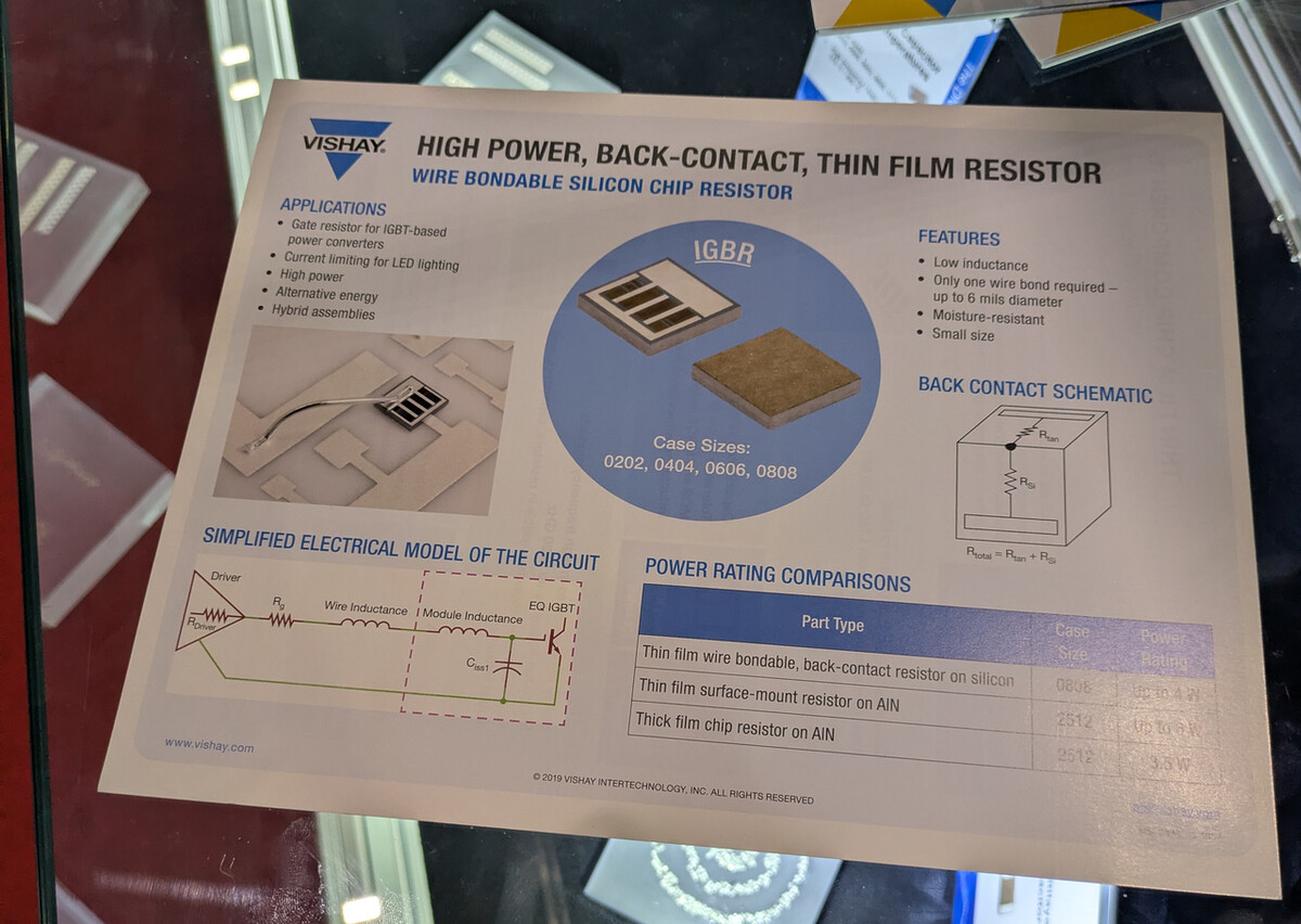
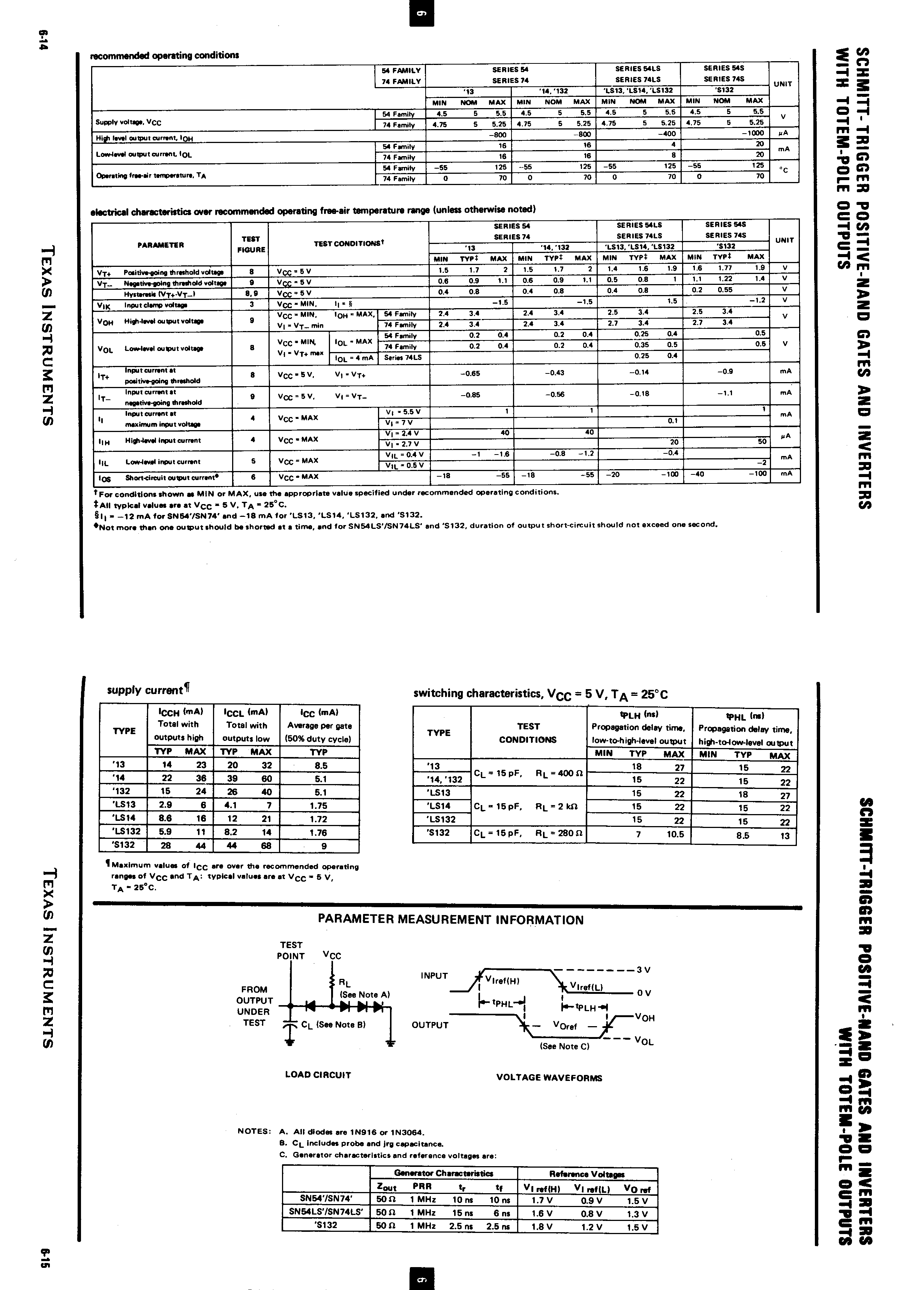
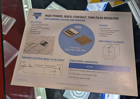
VISHAY HIGH POWER, BACK-CONTACT, THIN FILM RESISTOR
WIRE BONDABLE SILICON CHIP RESISTOR
APPLICATIONS
Gate resistor for IGBT-based power converters
Current limiting for LED lighting
High power
Alternative energy
Hybrid assemblies
FEATURES
Low inductance
Only one wire bond required – up to 6 mils diameter
Moisture-resistant
Small size
Case Sizes: 0202, 0404, 0606, 0808
BACK CONTACT SCHEMATIC
SIMPLIFIED ELECTRICAL MODEL OF THE CIRCUIT
POWER
, HIGH); } else { digitalWrite(LED_PMODE, LOW); } // is there an error? if (ISPError) { digitalWrite(LED_ERR, HIGH); } else { digitalWrite(LED_ERR, LOW); } // light the heartbeat LED heartbeat(); if (SERIAL.available
Simplified Block Diagram www.onsemi.com 3 NFAQ1560R43T PIN FUNCTION DESCRIPTION Pin Name Description 1 VSS Low−Side Common Supply Ground 2 VDD Low−Side Bias Voltage for IC and IGBTs Driving 3 HIN(U) Signal Input for High−Side U Phase 4 HIN(V) Signal Input for High−Side V Phase 5 HIN(W) Signal Input for High−
HIGH level driver (4) and the device may be impaired. Provisions should be made in system design and testing The phase splitter (2) provides the inversion LOW level driver (5) on simultaneously. to limit voltages and currents as shown be low. and amplification in the circuit. It determinesThe level shifter (3) and HIGH level driver (4) whether the outputs are active level HIGH or combine to form an emitter follower circuit active level
data transmission time : Name Min. Standard Max. Unit value T Code period 1.20 -- -- µs T0H 0 code, high level 0.2 0.3 0.4 µs time 0 code, low level T0L time 0.8 0.9 1.0 µs T1H 1 code, high level 0.6 0.65 1.0 µs time 1 code, low level T1L time 0.2 0.55 0.6 µs Reset code low Trst level time >80 -- -- µs 1. The protocol uses a unipolar zeroing code. Each symbol must have a low level. Each symbol in this protocol starts with a high level. The high time width determines the "0" or "1" code. . 2. When writing programs, the minimum symbol period is 1.2μs. 3. The high time of
to 47μF)for a bootstrap. In this case, a bottom element is turned ON (setting LIN1 to LIN3 in the lower side control signal input block to high) to charge CB. (When not using bootstrap circuit, each upper side pre-drive power supply needs an independent power supply. Externally set.) In addition, please
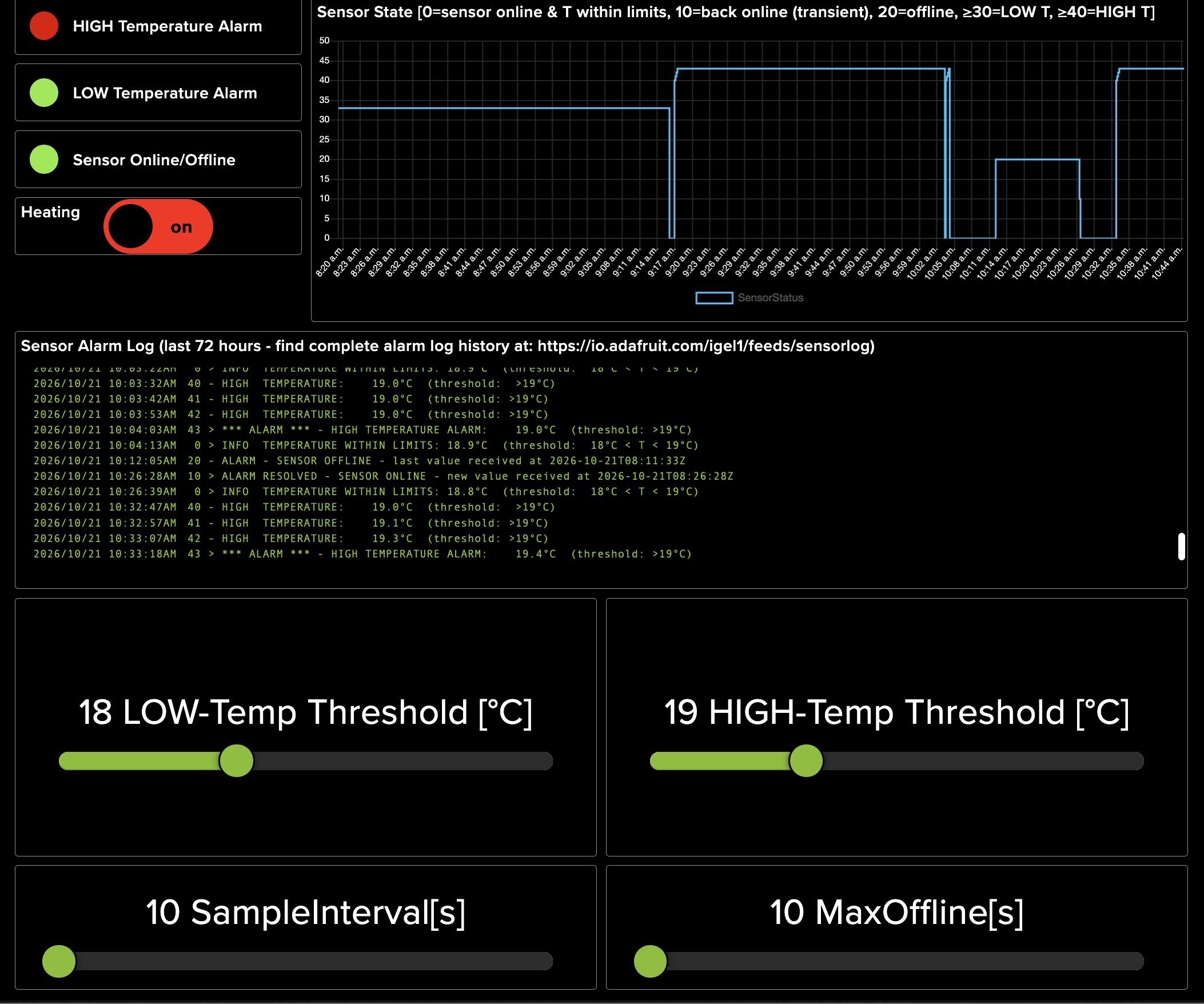
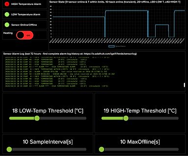
HIGH Temperature Alarm
LOW Temperature Alarm
Sensor Online/Offline
Heating on
Sensor State [0=sensor online & T within limits, 10=back online (transient), 20=offline, >=30=LOW T, >=40=HIGH T]
SensorStatus
— 120 µs Data transmission rate F MAX Duty ratio50% 400 —— —— Kbps Input capcity CI —— —— —— 15 pF Low Speed mode time T0H 0 code,high voltage time 0.5 µs ±150ns T1H 1 code,high voltage time 1.2 µs ±150ns T0L 0 code,low voltage time 2.0 µs ±150ns T1L 1 code,low voltage time 1.3 µs ±150ns RES low voltage time Above 50µs Note: It is one half of the time when high speed mode(reset time unchanged) http://www.world-semi.com WS2811 Signal line 256 Gray level 3 channal Constant current LED drive IC Sequence chart: D1 D2 D3 D4 T0L DIN DO DIN DO DIN DO 0 code T0H IC
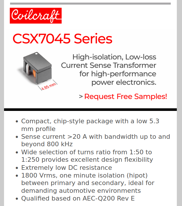
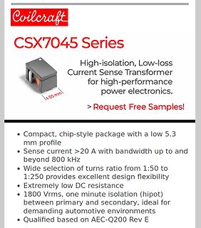
Coilcraft
CSX7045 Series
High-isolation, Low-loss Current Sense Transformer for high-performance power electronics.
> Request Free Samples!
• Compact, chip-style package with a low 5.3 mm profile
• Sense current >20 A with bandwidth
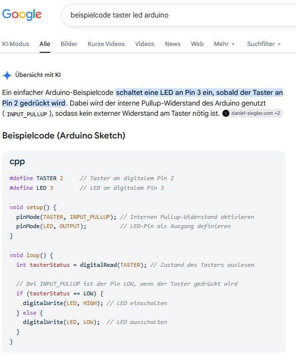
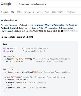
tasterStatus = digitalRead(TASTER); // Zustand des Tasters auslesen
// Bei INPUT_PULLUP ist der Pin LOW, wenn der Taster gedrückt wird
if (tasterStatus == LOW) {
digitalWrite(LED, HIGH); // LED einschalten
} else {
digitalWrite(LED, LOW); // LED ausschalten
}
Semiconductor Korea 1F1 --- 1F7 VOLTAGE RANGE: 50 --- 1000 V FAST RECOVERY RECTIFIER CURRENT: 1.0 A FEATURES Low cost Diffused junction Low leakage R - 1 Low forward voltage drop High current capability Easilycleaned with Freon,Alcohol,Isopropanol and similar solvents The plastic material carries U/L recognition
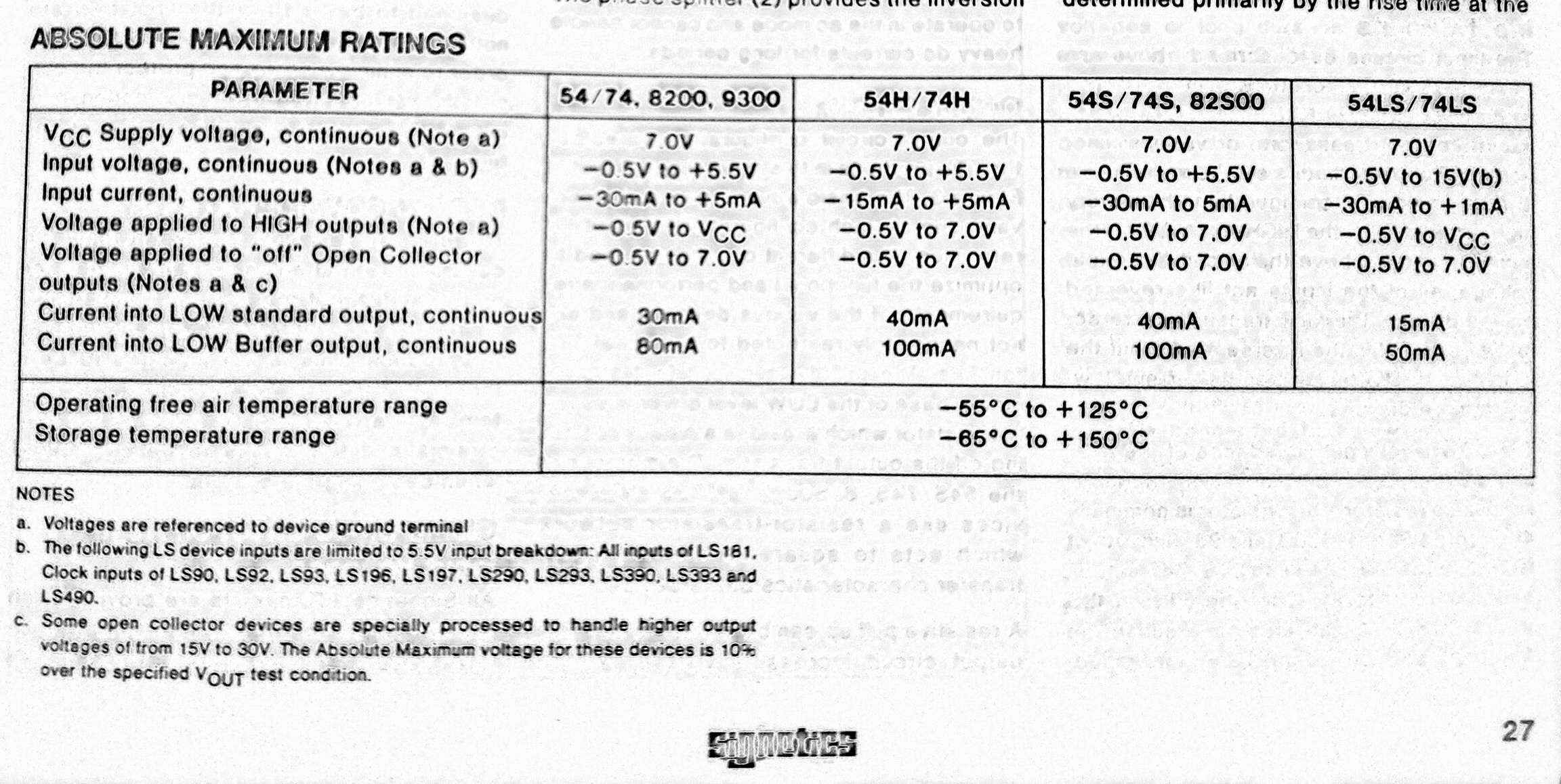
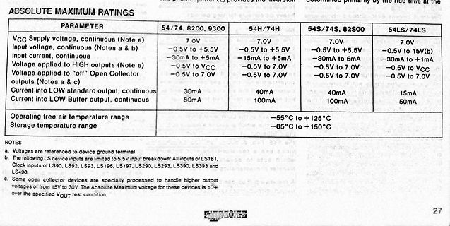
Input current, continuous
-30mA to +5mA
-15mA to +5mA
-30mA to 5mA
-30mA to +1mA
Voltage applied to HIGH outputs (Note a)
-0.5V to VCC
-0.5V to 7.0V
-0.5V to 7.0V
-0.5V to VCC
Voltage applied to "off" Open Collector outputs (Notes a & c)
-0.5V to 7.0V
-0.5V to 7.0V
-0.5V to 7.0V
-0.5V to 7.0V
Current into LOW standard output, continuous
30mA
40mA
40mA
15mA
Current into LOW Buffer, continuous
80mA
100mA
100mA
50mA
Operating free air temperature range
-55°C to +125°C
Storage temperature range
-65°C to +150
(z.B. Einzelne Zellpotenziale für die VC5 VC1=16.8V, VC2=12.6V, Überwachung VC3=8.4V...) DO (Pin HIGH (Spannung nahe VCC oder Entlade-MOSFET ist durchgeschaltet / 14) interner Reglerspannung, z.B. freigegeben >10V) CO (Pin HIGH (Spannung nahe VCC oder Lade-MOSFET ist durchgeschaltet / 15) interner Reglerspannung
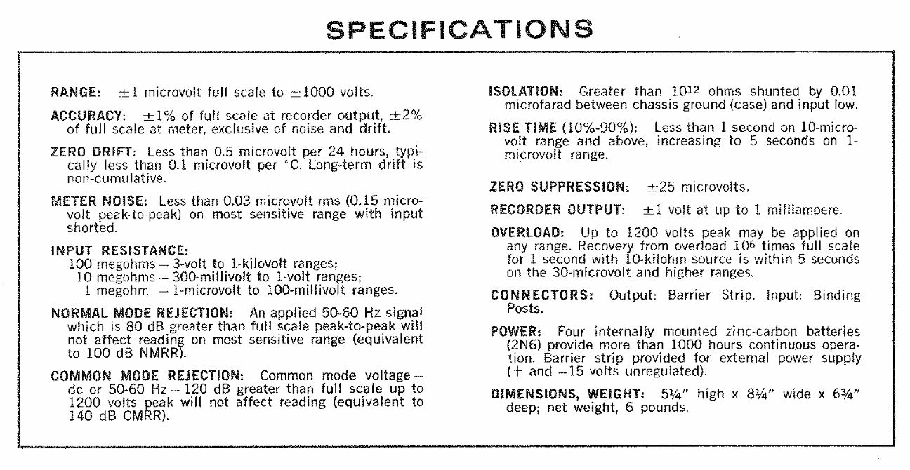
any range. Recovery from overload 10^6 times full scale within 5 seconds on the 30-microvolt and higher ranges.
CONNECTORS: Output: Barrier Strip. Input: Binding Posts.
POWER: Four internally mounted zinc-carbon batteries (2N6) provide more than 1000 hours continuous operation. Barrier strip provided for external power supply (+ and - 15 volts unregulated).
DIMENSIONS, WEIGHT: 5 1/4" high x 8 1/4" wide x 6 3/4" deep; net weight, 6 pounds.
mode. The temperature in the sauna room is lower (approx. 40 to 65 °C) than in sauna mode, with the relative humidity being considerably higher, spanning 35% to approximately 70%. The maximum humidity level which can be set depends on the temperature of the sauna. The higher the sauna temperature, the lower the maximum humidity level which can be set. The indicator light4 , 5 and b -g are green during climate mode. WORLD OF WELLNESS Heruntergeladen von manualslib.de Handbücher-Suchmachiene
1029 U, S III, S IV 111-1, IV-1 7-5, 10-12 Uan6 H {>n III-2, IV-2 6-5, 11-12 L IUp) Steuerspannung HIGH: $ USH = 3,3 V Eingangssperrstrom HIGH: sh = 1 PA 11 Steuerspannung LOW: USL =2,1 V i Steuerstrom LOW: - /SL = 200 pA i Schalter- Steuerung Schaltersteuerung TDA 1029 11 11 11 Eingeschaltete Durchgeschaltete
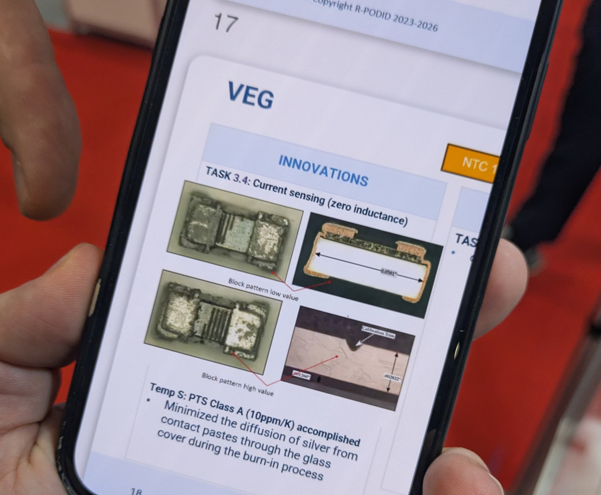
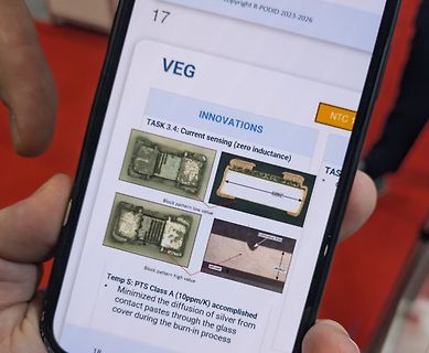
17
VEG
INNOVATIONS
TASK 3.4: Current sensing (zero inductance)
Block pattern low value
Block pattern high value
Temp S: PTS Class A (10ppm/K) accomplished
Minimized the diffusion of silver from contact pastes through the glass cover during the burn-in process
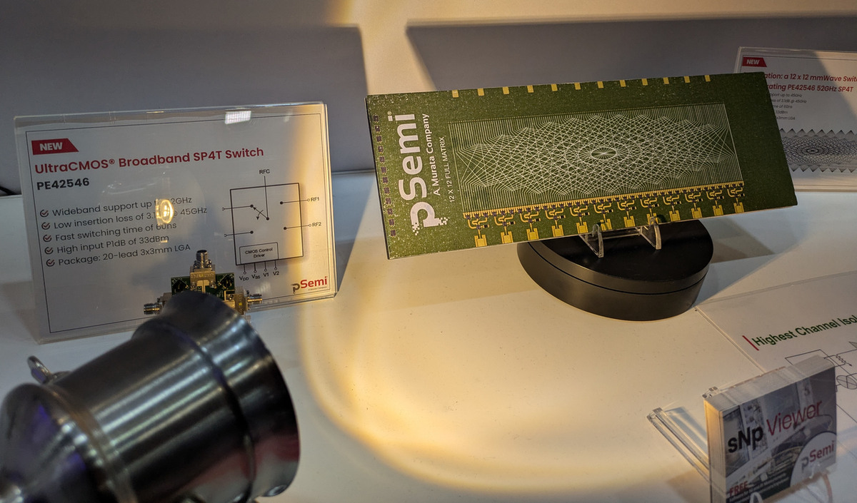
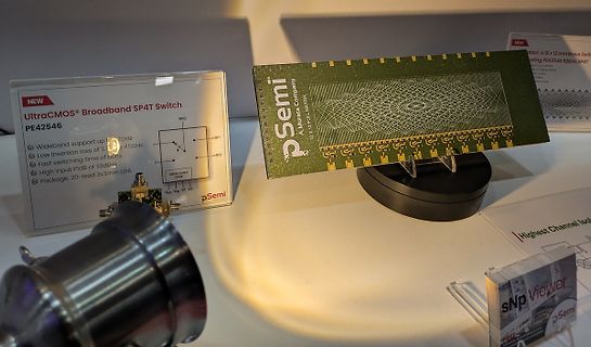
NEW UltraCMOS® Broadband SP4T Switch PE42546 Wideband support up to 6 GHz Low insertion loss of 3 dB @ 6 GHz Fast switching time of bonus High input P1dB of 33 dBm Package: 20-lead 3x3mm LGA pSemi A Murata Company 12 X 12781 MATRIX
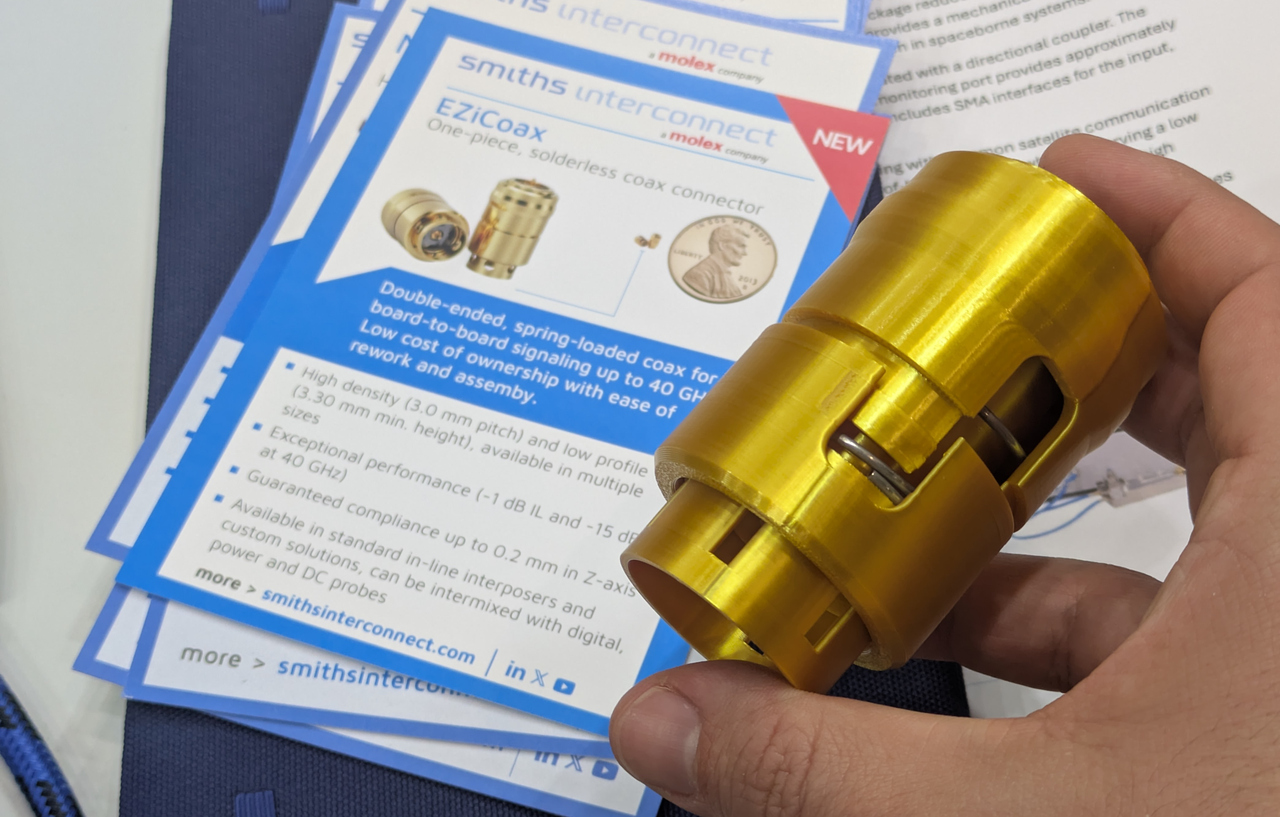
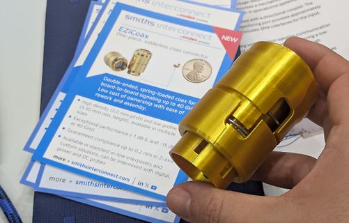
solderless coax connector
Double-ended, spring-loaded coax for board-to-board signaling up to 40 GHz
High density (3.0 mm pitch) and low profile (3.30 mm min. height), available in multiple sizes
Exceptional performance (-1 dB IL and -15 dB return loss at 40 GHz)
Guaranteed compliance up to 0.2 mm in Z-axis
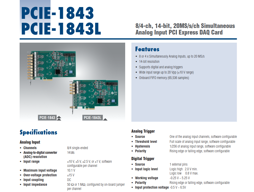
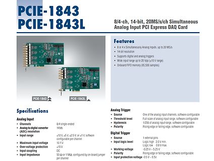
falling edge, software configurable Digital Trigger Source 1 external pins Input logic level Logic high 2.0 V min, Logic low 0.8 V max. Working voltage -0.25 V ~ 5.25 V Polarity Rising edge or falling edge, software configurable Input protection voltage -0.5 V ~ 6.5 V
/ OFF Control External switch or NPN Transistor to turn ON / OFF Power OK Signal Open drain signal low when PSU turns on, Max. sink current: 20mA, Max. drain voltage: 40V. Working Temp. -20 ~ +70°C (Refer to de-rating curve) Working Humidity 20 ~ 90% RH non-condensing Storage Temp. & Humidity -40 ~ +
technology expertise has enabled the development of the Chip CERALOCK ® with built-in load capacitance. High-density mounting can be realized because of the small package and the elimination of the need for an external load capacitor. !FEATURES 1. Oscillation circuits do not require external load capacitors
Phasen-Inverter-Hybrid-IC (IPM). Es bündelt die komplette 3-Phasen-Brücke (6 IGBTs samt Freilaufdioden), die High-Side- und Low-Side-Gate-Treiber sowie eine integrierte Überstrom- (ITRIP) und Unterspannungsschutzschaltung in einem monolithischen ZIP- Gehäuse. Ovaga Technologies +2 Dass es dieses Bauteil erwischt

 Bild
Bild
 Bild
Bild
 Bild
Bild
 Bild
Bild
 Bild
Bild
 Bild
Bild

 Bild
Bild
 Bild
Bild
 Bild
Bild
 Bild
Bild
 Bild
Bild
 Bild
Bild
 Bild
Bild
 Bild
Bild
 Bild
Bild
 Bild
Bild