-
 Bild
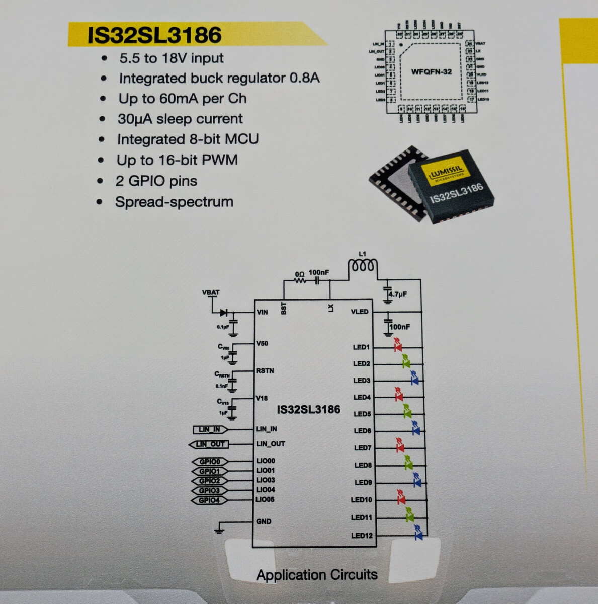
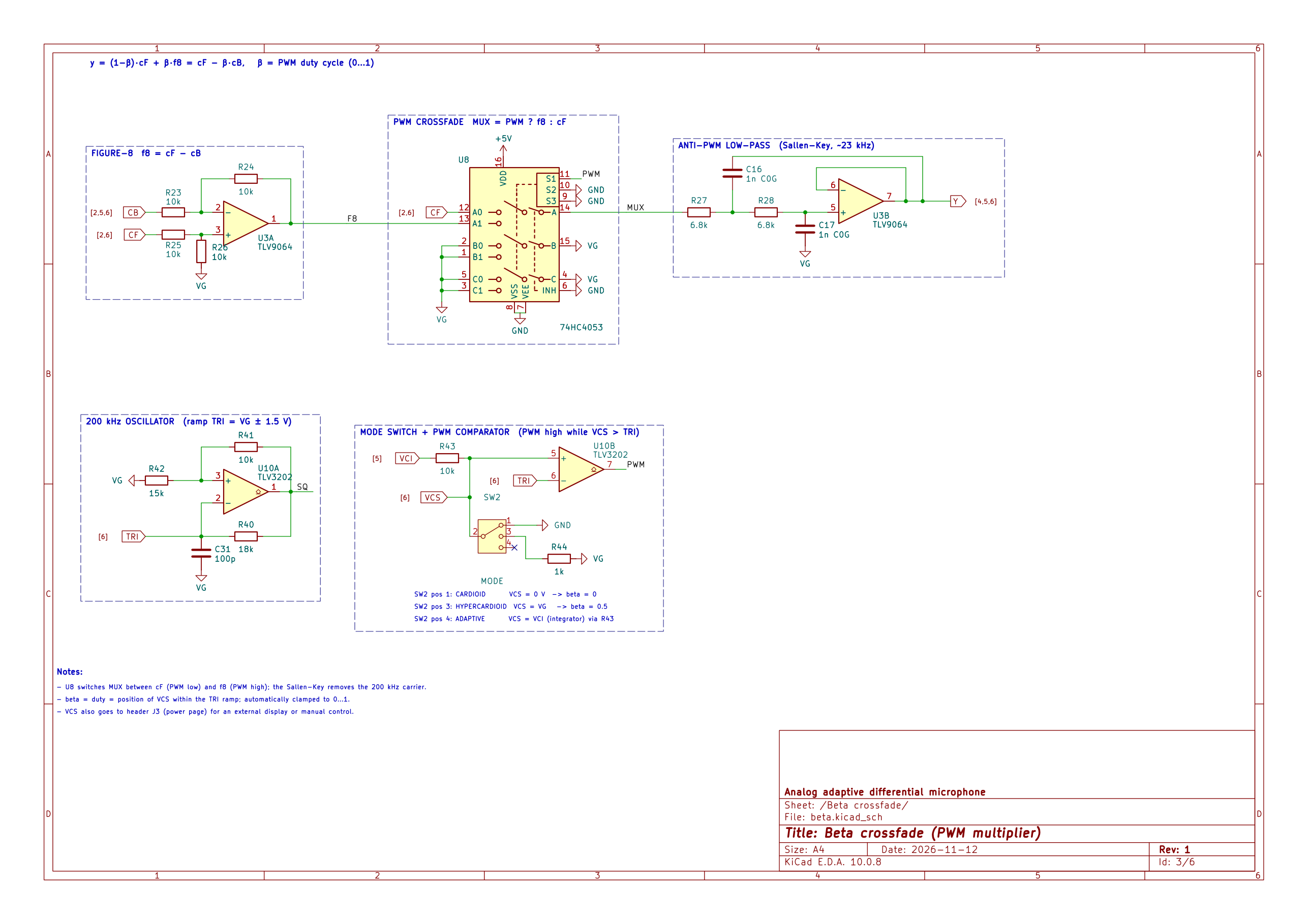
Datenblattseite mit IS32SL3186 Eigenschaften und Schaltplan
Integrated buck regulator 0.8A Up to 60mA per Ch 30µA sleep current Integrated 8-bit MCU Up to 16-bit PWM 2 GPIO pins Spread-spectrum VBAT L1 10µH 100nF VLED 100nF VIN CSTB CSTN RSTN V18 CPST LIN_IN LIN_OUT GPIO0 bis GPIO4 LIO00 bis LIO05 GND LED1 bis LED12 Application Circuits
-
 Bild
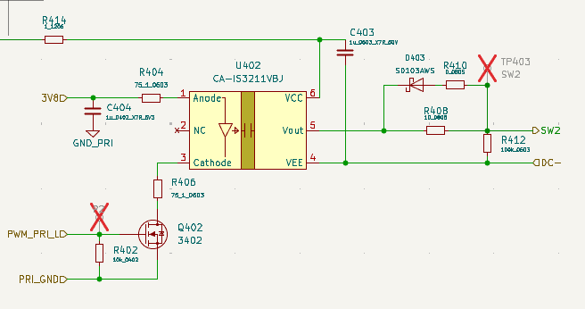
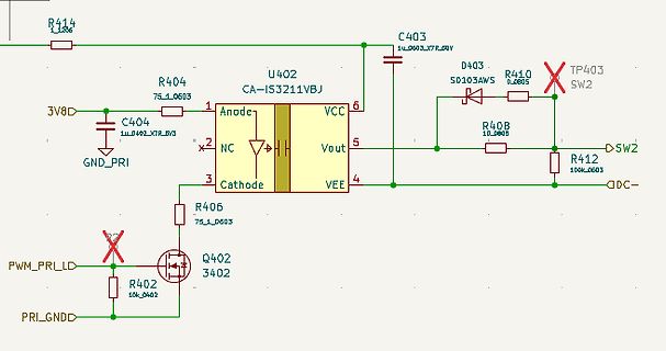
Schaltplan eines elektronischen Bauteils
SD103AWS R410 0603 TP403 SW2 R408 10_0603 Vout VEE R412 100k_0603 SW2 DC- R406 75_1_0603 Q402 3402 PWM_PRI_LD R402 10k_0402 PRI_GNDD
-
 Bild
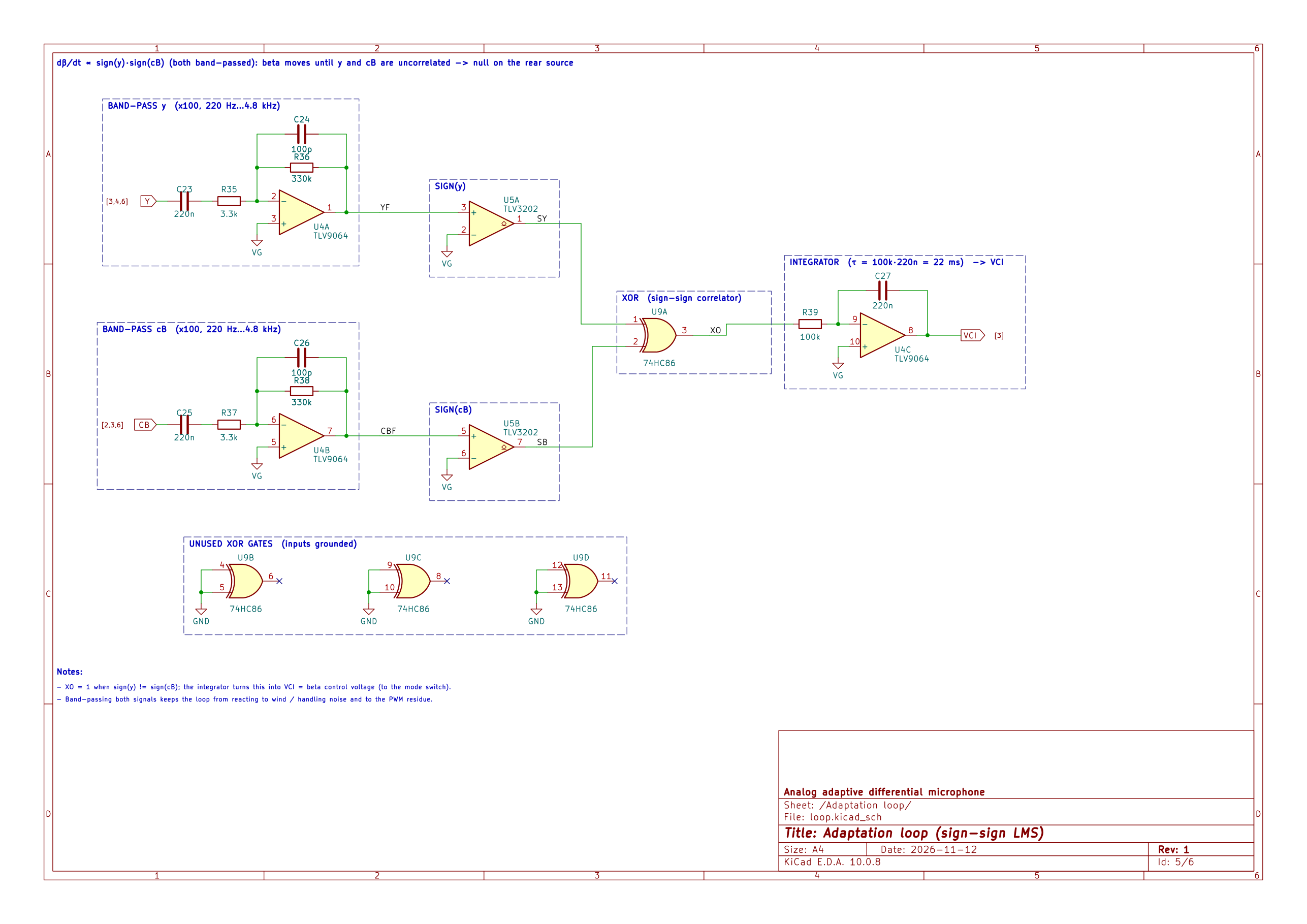
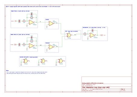
Schaltplan eines adaptiven Mikrofon-LMS-Algorithmus
switch). - Band-passing both signals keeps the loop from reacting to wind / handling noise and to the PWM residue. Analog adaptive differential microphone Sheet: Adaptation loop/ File: loop_LMS.sch Title: Adaptation loop (sign-sign LMS) Size: A4 Date: 2026-11-12 Rev: 1 Id: 5/6 KiCad E.D.A. 10.0.8
-
 Bild
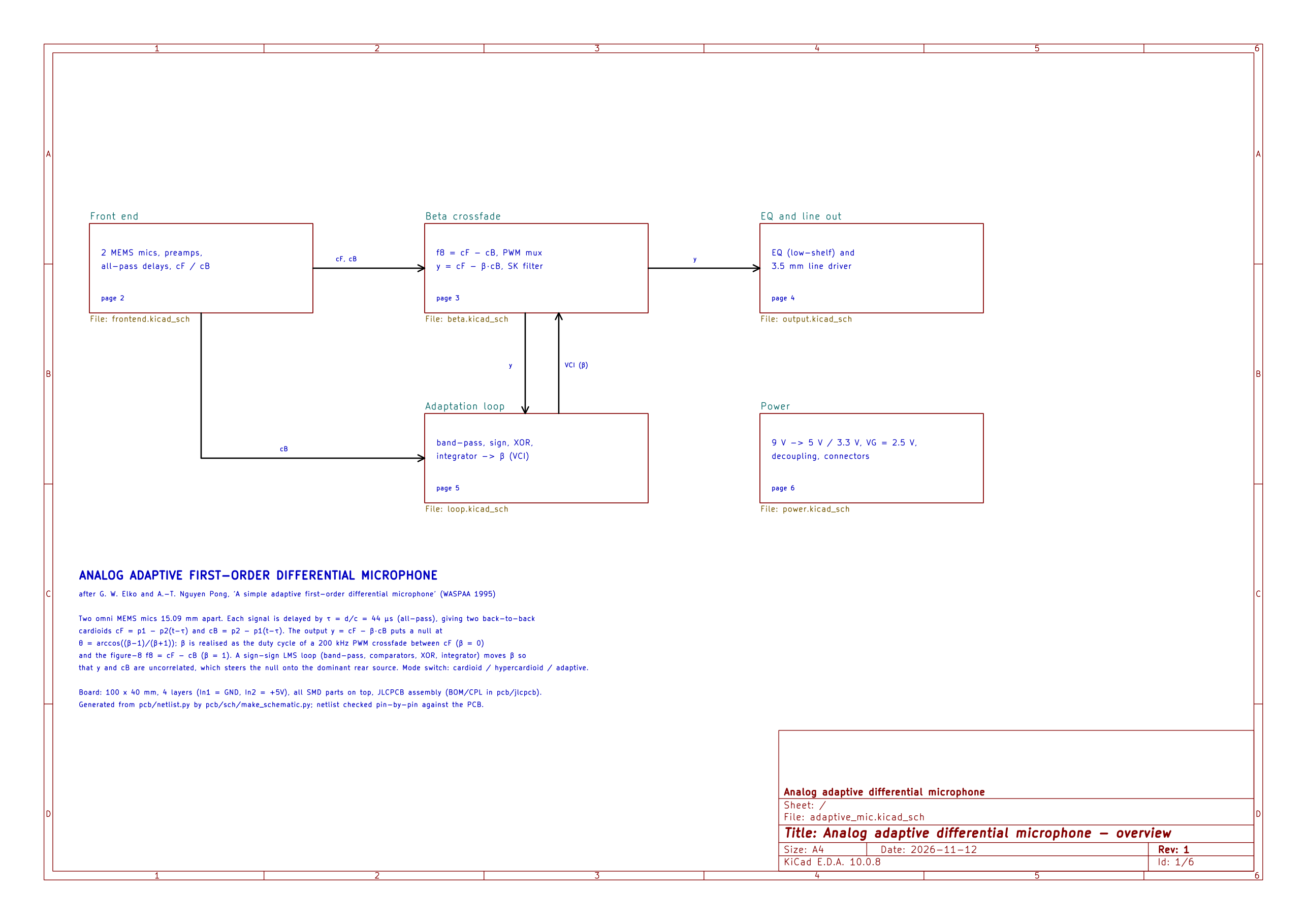
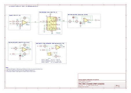
Schaltplan eines analogen adaptiven Differenzmikrofons
y = (1-β)cf + βf = cf - cβ, β = PWM duty cycle (0...1) FIGURE-B fb = cf - cβ R23 10k, R25 10k, U34 TLV9064, 2[a] CF, CB, R26 10k, R28 6.8k, U3B TLV9064, C16, C17, ANTI-PWM LOW-PASS, 7 [4.5A] 200 kHz OSCILLATOR, R41 10k, R42 15k, U35A TLV5202, [5] VCI, [6] TRI, SQ, R40 18k, C31 100p, MODE SWITCH + PWM COMPARATOR, PWM high VCS = VCI, SW2, SW3, SW4, ADAPTIVE, Analog adaptive differential microphone Beta crossfade/switch, KiCad E.A. 10.0.8, Date: 2026-11-12, Rev: 1, Id: 3/6
-
 Bild
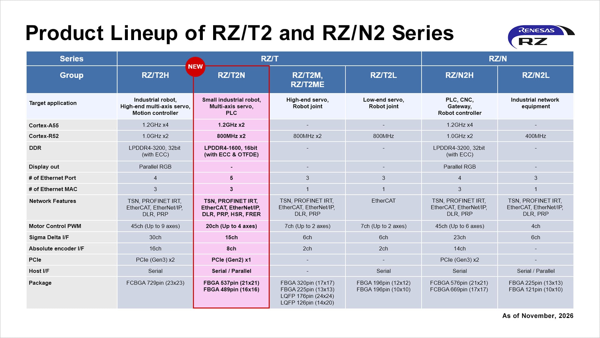
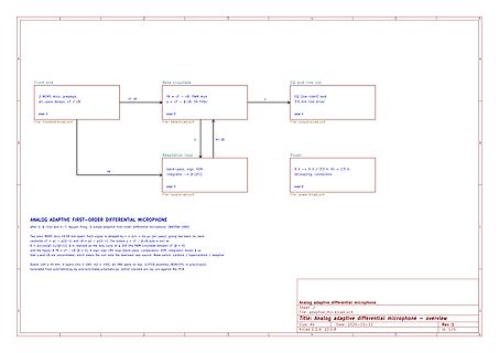
Blockschaltbild eines adaptiven differentiellen Mikrofons
Front end, 2 MEMS mics, preamps, all-pass delays, cf / cB, Beta crossfade, YB = cf - cB, PWM mux, y = cf - beta cB, SK filter, EQ and line out, EQ (low-shelf) and 3.5 mm line driver, Adaptation loop, band-pass, sig, XDR, integrator -> beta (VCI), Power, 9 V -> 5 V, VG = 2.5 V, ANALOG ADAPTIVE
-
 Bild
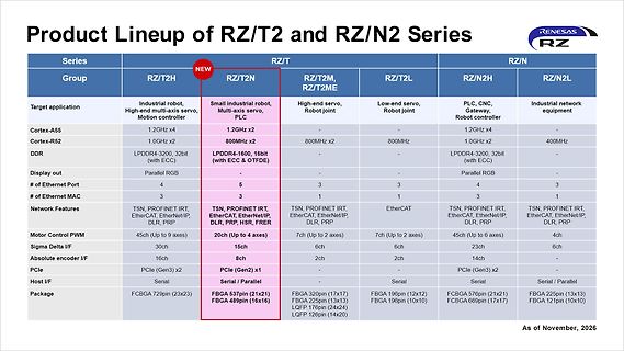
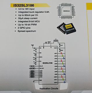
Produktübersicht Renesas RZ/T und RZ/N Serien
PROFINET, EtherCAT, Ethernet/IP, DLR, PRP TSN, PROFINET, EtherCAT, Ethernet/IP, DLR, PRP Motor Control PWM 45ch (Up to 2 axes) 20ch (Up to 4 axes) 7ch (Up to 2 axes) 7ch (Up to 2 axes) 45ch (Up to 6 axes) 4ch Sigma Delta I/F 15ch 6ch 6ch 23ch 4ch Absolute encoder I/F 30ch 16ch 8ch 2ch 2ch 14ch PCIe 2ch PCIe