TMS70Cx8 Devices
4.1 TMS70Cx8 Key Features
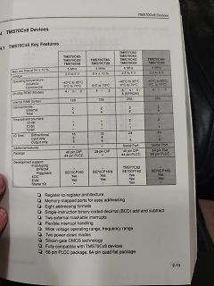
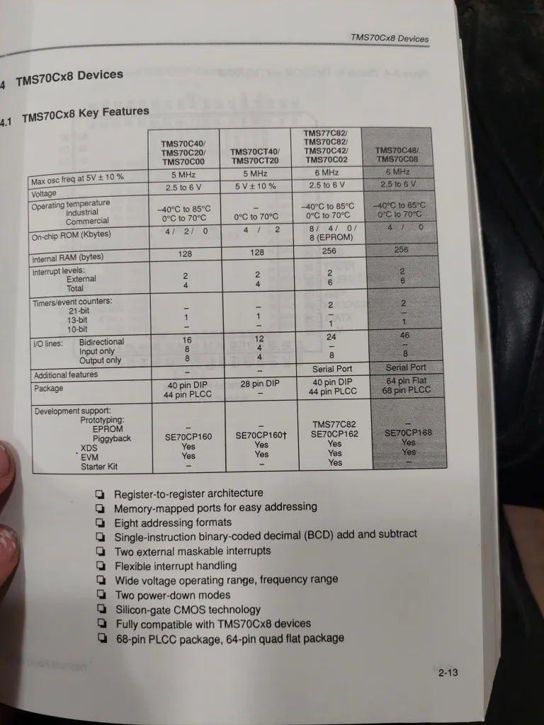
TMS70C40/TMS70C20/TMS70C00
Max osc freq at 5V ± 10%
5 MHz
Voltage
2.5 to 6 V
Operating temperature
Industrial
Commercial
-40°C to 85°C
0°C to 70°C
TMS70CT40/TMS70CT20
5 MHz
5V ± 10%
128
Internal RAM (bytes)
128
256
256
TMS70C82/TMS70C82/TMS70C42/TMS70C02
6 MHz
2.5 to 6 V
-40°C to 85°C
0°C to 70°C
TMS70C48/TMS70C08
6 MHz
2.5 to 6 V
-40°C to 85°C
0°C to 70°C
Interrupt levels:
External
Total
2
6
2
6
2
6
2
6
I/O lines
ab. https://www.spiegel.de/ausland/china-humanoide-roboter-zeigen-kung-fu-im-staatsfernsehen-a-746c4dec-ac7c-437d-ba39-6934f04b1a18
Michael K. schrieb im Beitrag #8017995: > Nur das C3PO nicht Rücken bekommt und dann KK und Staat noch ne Mio > kostet bis er sich zu Tode säuft. Kauft der C3PO auch einen Kleinwagen? Wenn also alle Produktiv leistenden Arbeitende von C3PO Kopien
above 25⋅C at the following rates: D-14 package at 7.8mW/⋅C D-8 package at 6.3mW/⋅C N-14 package at 11.5mW/⋅C N-8 package at 9.3mW/⋅C April 15, 1992 251 Philips Semiconductors RF Communications Products Product
event pending flag, set by H/W while WKT time out WKTIF 0C.3 W 0 write 0: clear this flag; write 1: no action R - INT2 (PA7 or PB5) interrupt event pending flag, set by H/W at INT2 INT2IF 0C.2 pin’s falling edge W 0 write 0: clear this flag; write 1: no action INT1 (PA1 or PB1) interrupt event pending flag, set by H/W at INT1 INT1IF 0C.1 R - pin’s falling/rising edge W 0 write 0: clear this flag; write 1: no action R - INT0 (PA3 or PB2) interrupt event pending flag, set by H/W at INT0 INT0IF 0C.0 pin’s falling/rising
a single XML file Web Server, ZeroConf, Auto-IP, Messenger, IPv4/IPv6, … Questions: FRDM-K64F (ab 24 Euro). Ethernetbuchse eingebaut ARM® Cortex™-M4 Core with Floating point unit and DSP 120MHz, 256KB RAM, 1MB FLASH SPI (3) I2C (3) I2S UART (5) USB OTG / Host / Device USB regulator PWM ADC (2x 16bit
Uno (ca. 24 EUR) mit Ethernet Shield (ca. 35 EUR) oder Arduino Ethernet (ca. 48 EUR) private Projekte. avrETH1. winzige Maße: 32mm x 47.8mm x ~20mm (BxLxH) Microchip ENC28J60 Ethernetcontroller Atmel Atmega32 uC
The hardware interrupt occurs during the address calculation period (at the end of each line). If a MSB = 0 command is sent to the T6963C during this period, the T6963C enters Wait status. If a status check is not carried out in this state before the next command is sent
brauchst Du kyroflux, das ist ein USB-FDC, der sämtliche Formate versteht (auch die GCR-Formate von C64, Apple II und Co). https://kryoflux.com/ Um Nutzdaten von den Disketten herunterzubekommen, musst Du natürlich noch wissen, wie genau sie formatiert sind (Sektorgröße, -Anzahl etc.), aber da
Dieter S. schrieb im Beitrag #7968209: > - Das Diskettenlaufwerk benötigt -5 Volt, +5 Volt, +24 Volt und 115 Volt > AC für den Laufwerksmotor, zur Spannungsversorgung wurde das Netzteil > aus der FDU 990 verwendet. Läuft das Laufwerk bei 50 Hz statt 60 Hz Netzfrequenz dann langsamer oder
glitch capture (100 ns dual channel) from 5 s/div to 50 s/div Average Number of averages selectable at 8, 64, and 256 Roll Mode At sweep speeds of 200 ms/div and slower, waveform data moves across the display from right to left with no dead time. Display can be either free-running (non-triggered) or triggered
following compression directives c.lbu/c.lhu/c.sb/c.sh/c.lbusp/c.lhusp/c.sbsp/c.shsp,usebasedontheMRScompilerorthetoolchainitprovides. 1.2 Register set RV32E is a subset of RV32I, which has only half of its registers. That is, there are
Cascade method: D1 D2 D3 D4 DIN DO DIN DO DIN DO PIX1 PIX2 PIX3 Data transmission method: re se t c o d e > = 5 0 u s re se t c o d e D a ta re fre sh c y c le 1 D a ta re fre sh c y c le 2 se c o n d se c o n d D 1 first 2 4 b 2 4 b ith ird 2 4 b it first 2 4 b2 4 b itth ird 2 4 b it s2 4 b ith ird
plus ESM, and optional break/bug fix support), priced at a 50% premium over standard Ubuntu Pro. This applies whether you’re approaching that milestone with 16.04 LTS or already using the Legacy add-on with 14.04 LTS. [/c] ### EMV 2026 – Vorbereitungen
Singularität. Die Mesago hat soeben die folgenden Informationen über die nächste Ausgabe der EMV versendet: [c] Noch gut fünf Monate bis die EMV – die internationale Fachmesse für Elektromagnetische Verträglichkeit mit Kongress und Workshops – ihre Tore vom 24. – 26.03.2026 in Köln öffnet. Bereits jetzt sind
send by MCU, and D2, D3, D4 through pixel internal reshaping amplificat.on to transmit Composition of 24bit Data G7 G6 G5 G4 G3 G2 G1 G0 R7 R6 R5 R4 R3 R2 R1 R0 B7 B6 B5 B4 B3 B2 B1 B0 Note: Data transmit in order of GRB, high bit data at first. TypicalApplication Circuit: No need extra filter capacitor
0F65 C 4 0 0 LDI 00 0FA45 3 F XPPC 3 0 F 2 6 C417 LDI17 3 1 XPAL 1 C 0 0 F LD HOURS 0 F 2 8 33 XPAL3 0F67 C 0 4 A LD SEC 0 F 2 9 C40F LDI 0F 0F6A 0 2 CCL 0FA87 0 3 2 4 SCL 24 0 F 2 B 37 XPAH 3 B E C 0 1 DAI
Rev 1.2 Time base and Watchdog Timer (WDT) The time base generator and WDT share the same divided (/256) counter. TIMERDIS/EN/CLR, WDT DIS/EN/CLR and IRQ EN/DIS are independent from each other. Once the WDT time-out occurs, the IRQ pin will remain at logic low level until the CLR WDT oIRQhe DIS command
applied to theTVS without operation V Breakdown Voltage -- Maximum voltage that flows though theTVS at a specified test current (I ) BR T V Clamping Voltage -- Peak voltage measured across theTVS at a specified Ippm (peak impulse current) C IR Reverse Leakage Current -- Current measured at V R VF Forward
Keil8051 (teuer). Ach ja, und mir fehlt die passende Anwendung für die alten Dinger. Habe noch 65 Stck. At89C52ED2, die waren mir vor 15 Jahren Gold wert aber heute?
LED Strom in SOP20/SOP28. und bis 12V auch an den Eingängen/Ausgängen arbeiten Micronas HVC22xyA HVC24xyA und Infineon TLE7810G und Holteks HT66F2730 hat einen Spannungsregler drin Oder bis 300 GradC arbeitende https://www.blikai.com/productdetail/honeywell-aerospace-ht83c51-2046731
by MCU, and D2, D3, D4 through pixel internal reshaping amplification to transmit. Composition of 24bit data G7 G6 G5 G4 G3 G2 G1 G0 R7 R6 R5 R4 R3 R2 R1 R0 B7 B6 B5 B4 B3 B2 B1 B0 Note: Data transmit in order of GRB, high bit data at first. 5 / 6 http://www.world-semi.com WS2812D-F8_15mA Intelligent control LED integrated light source Typical application circuit D N 75R L1 C1 4 Din 3 GND 2 VDD 104 1 Dout 5V WS2812D 75R L2 C2 4 3 Din GND 2 VDD 104 1 Dout 5V WS2812D 75R Ln Cn 4 Din 3 GND 2 VDD 104 1 Dout 5V o WS2812D t Modify Records Version № Status Bar Modify Content Summary
to 10 ±8 g FS bit set to 00 1024 LSB/g So Sensitivity FS bit set to 01 512 LSB/g FS bit set to 10 256 LSB/g TCSo Sensitivity change vs. temperaturFS bit set to 00 ±0.01 %/°C Tyoff Typical zero-g level offset accuracy ±80 mg Tcoff Zero-g level change vs. temperatuMax delta from 2C° ±0.6 mg/°C FS bit
nicht davon weg, dass man verstehen muss, was programmiert werden soll. Das ganze für Embedded C und C#
präferierte online-KI zu befragen: den prompt hab ich ähnlich wie hier vorgemacht wurde knapp gehalten: "C-code for ATmega48, RTC @ 32768 Hz, power saving mode, LED blinking at 50ms interval" ich kenn den Atmega48 nicht, bin entfernt vertraut mit den Megas, kann den ausgespuckten Code also nicht wirklich
data[0], (int16_t)data[1], (int16_t)data[2]); BME280_CalculateTemperature (RawTemp, &FineTemp, &DegC100Temp); /* ** Do the compensation computation as of Bosch documentation page 25. ** Computes the pressure in unsigned 32 bit integer in Q24.8 format (24 integer bit, 8 fractional bits). ** Example:
560 VDC DC Voltage Capacitance Range 0.010 – 10 µF Capacitance Values E6 series (IEC 60063) measured at 1 kHz and +20±1°C Capacitance Tolerance ±10%, ±20% Operating Temperature Range −40°C to +110°C Rated Temperature +110°C Climatic Category 40/110/56 IEC 60068-1 Storage time: ≤ 24 months from the date
is optimized for use in many AT24C01A industrial and commercial applications where low power and low voltage operation are essential. The AT24C01A/02/04/08/16 is available in space saving 8-pin PDIP, AT24C02 (AT24C01A/02 /0 4/08 /1 6), 8-Pin MSOP (AT24C01A/02), 8-Pin TSSOP (AT24C01A/02/04/08/16), and 8-Pin and 14-Pin JEDEC SOIC (AT24C01A/02/04/08/16) packages and is accessed via a 2-wire serial interface. In AT24C04 addition, the entire family is
IEC 134) VSS = 0V; VSSA= 0V; VSSPA= 0V PARAMETER MIN MAX UNIT Operating temperature range -40 +85 °C Storage temperature range -55 +125 °C Voltage at any I/O and BATpin to SS -0.5 3.6 V Voltage at PAOUT pin to SS -0.5 7.2 V Voltage at any I/O pin tSSV -0.5 V BAT+0.3 V Peak output current port P1x and
connected toSS : BS0, BS2, CL, D[7:3], E, R/W#, CS#, D/C#, BGGND, LS Pin internally connected toDD : BS1, CLS VBAT, C1P, C1N, C2P, C2N, FR should be left open. C1, C2: 2.2uF (1) C3: 1.0uF (1) RP: Pull up resistor Voltage at I = V – 3V. For V = 12V, I = 30uA
connected toSS : BS0, BS2, CL, D[7:3], E, R/W#, CS#, D/C#, BGGND, LS Pin internally connected toDD : BS1, CLS VBAT, C1P, C1N, C2P, C2N, FR should be left open. C1, C2: 2.2uF (1) C3: 1.0uF (1) RP: Pull up resistor Voltage at I = V – 3V. For V = 12V, I = 30uA
zusammen? Braucht man "einfach nur" eine größere GPU? Welche genau? PS: Da die LLMs ja Probleme mit C und C++ haben - hilft es, den Code erst in Python erstellen und dann nach C / C++ konvertieren zu lassen?
Garnicht so übel. Mein AtMega8535 wollte einfach nicht so richtig bei TWI. Und Fehler in Google eingegeben, KI Antwort: Zitat: "...Nutzen Sie innerhalb von i2c_write für die TWI-Steuerung und die Warteschleife ein anderes
High Load Current vs. V IN. Waveforms. 2011 Microchip Technology Inc. DS22234B-page 7 MCP1640/B/C/D Note: Unless otherwise indicaVIN= EN = 1.2VOUT= IN= 10 µF, L = 4.7OUT,= 3.3VLOAD= 15 mA,AT = +25°C. FIGURE 2-19: 3.3V Start-up After Enable. FIGURE 2-22: MCP1640B 3.3V V OUT Load Transient Waveforms
transmitted as a one if the operating voltage has dropped below the low voltage trip point, typically 3.8V at 25°C. This Vsignal is If the supply voltage drops below the low voltage trip transmitted so the receiver can give an indication to the point, the LED output will be toggled at approximately user that
time at 12 MHz programmable Baudrate-Generators – 666 ns instruction cycle time at 18 MHz l Fully upward compatible with SAB 80C515, – 256 directly addressable bits SAB 80C517, SAB 80C515A – Boolean processor
haben. - 2.2 - CONITEC l H Christian LotDatensysteme G R I P - B e f e h l s s a t z D O P P E L E S C A P E - S E Q U E N Z E N K o n f i g u r a t i o n ESC ESC "0" a Spezifiziere V24-Empfängerbaudrate ESC ESC "l" a Spezifiziere V24-Senderbaudrate ESC ESC "3" a Spezifiziere serielle Tastatur-Baudrate
MHz maximum internal clock frequency ■ Oscillator supervisor ■ Fully static operation HiQUAD64 ■ -40°C to + 150°C temperature range ■ User EPROM/OTP: 16 Kbytes ■ Data RAM: 256 bytes ■ 10-bit analog-to-digital converter ■ Data EEPROM: 128 bytes ■ Software watchdog for system integrity ■ 64 pin HiQUAD64
Blitzrate: 1-7 Hz Anzahl der Farben: Farbrad 1: 7 dichroitische + weiß Farbrad 2: 2 Korrekturfilter + weiß 24 mögliche Farbmischungen Maße (LxBxH): 1220 x 440 x 410 mm Gewicht: 38,5 kg Maximale Umgebungstemperatur T : 45° C a Maximale Leuchtentemperatur im Beharrungszustand T :B 95° C Sicherung: F 10 A, 250
on page 1–24. H The instrument must have had a warm-up period of at least 20 minutes. H The instrument must have had its signal-path-compensation routine last executed after at least a 20 minute warm-up period at
schrieb: >Ach ja, die 5V ergeben sich daraus, dass das Ganze als >Hardware-Erweiterung an einem C64 laufen soll :) Der C64 hat auch noch 9V~ , daraus kann man mit einen Spannungsverdopplungsgleichrichter auch 18V machen. Siehe hier Seite 84: http://www.homecomputerworld.at/literatur/c64/Hardware_Basteleien_zum_C64_and_C128_(DE).pdf
enters 2·C 1∆t·V (c = 0)+I (c = 0) at position 1 of the right-hand side vector. Note thct I (t = 0) is zero because the voltage V1is applied at t = 0. Finally, the complete matrix equation writes as follows.
2.5 Interfaces Connector Side (CPU i5-7300U) USB 4 x USB Host 3.0 (Type A) 1 x USB Host 3.1 (Type C) Ethernet 2 x 1 Gbit Ethernet (Intel I219LM + I211AT) Communication 1 x RS-232 / RS422 / RS-485 (BIOS setting) (RJ50 10P10C) Video 1 x DisplayPort WLAN 1 x 802.11 ac/a/b/g/n 2.4 GHz, 5 GHz, (optional
example shows plateau characteristic taken at 25 °C along with those obtained at 150 °C, 175 °C, and 200 °C. Because the gain of the photomultiplier tube decreases as the temperature increases, the supply voltage at which the signal appears (corresponding
±.10] c No. of Dimensions Part Numbers I Positions A B C 15.24 Centerline g 25.10 27.94 30.48 r 24 .988 1.100 1.200 390263-7 e i 28 30.12 33.02 35.56 390263-1 n 1.190 1.300 1.400 E 32 35.20 38.10 40.64 390263
signalappliedtogether. ECO L : l y — 5 V —5V -0VCOUNTER B Z mise a | 7 p i ) F “ve GND _ Vapr813 (f] : — 7C E T ]OF T4LS10 2 02 A2 2 iY ! 3 3 A3 sh 2 3 Z E. G pg2_ ? T C eio1 Z) ; | | 15 i [ a Te C E P TL24 a D AT; CO:T i a CET sz Z : D1 01Kz 7BI BIs Z o e s | 3 03e ]83 35 Z i ; PE AcVCC GND VSS GND : 74LSI6I

 Bild
Bild