-
Thread
F-Droid-Projekt durch Google-Pläne in Gefahr
F-Droid-Projekt* stellt seit 15 Jahren einen alternativen Store für Android-Apps bereit, die unter Android per Side-Loading installiert werden können (z.B. OSM). Im September wird es ernst. Heise: https://www.heise.de/news/Keep-Android-Open-Abwehr-gegen-Verbot-anonymer-Apps-von-Google-10965483.html
-
Thread
Dringend: Kennt jemand das Mitglied Kolja L. (kolja82)? Gesperrt
musste. Naja, es gab und gibt ja immer noch die iframes, und Kenner konnten natürlich auch Server-Side Includes oder den Include-Befehl von PHP benutzen. > Damals hießen die Konkurrenten zu selbstgeschriebenen Skripten > "Frontpage", "Netscape Composer" oder "Joomla". Das sehe ich ehrlich gesagt
-
Thread
2 Geräte an einem µC UART
für die Dauer des Firmware Updates zum schweigen bringen. Erste Idee: der GPS Sender wird low side mit einem ULN2003A abgeschaltet. Vcc bleibt drann. => kann das funktionieren? oder können da Pegel auftreten, welche der NEO-6M nicht so mag und ich einen Hardwareschaden riskiere? Zur Sicherheit noch
-
Thread
ESD-Schutz für ADC
mal gar nicht ohne. - https://www.st.com/resource/en/application_note/an6249-how-to-protect-a-high-side-current-sensing-against-esd-stmicroelectronics.pdf Und solche Impulse werden nicht mit Widerständen bedämpft (die müssten dann ja diese 6kV aushalten), sondern mit TVS-Dioden, Induktivitäten und
-
Thread
[V] Smart High-side Power Switch BTS4141N
Ich hätte noch einige BTS4141N Bauform SOT223 Smart Highside Powerswitch: Short circuit protection Overload protection ... uC komnpatible Powerswitch Operating 12-45V / 1,4A 10 Stück: 2,50€
-
Thread
MIC5236 und verpolte Akkus
MIC5236 wird durch einen ohne Enable ersetzt und ein anderer Spannungsregler wird durch einen High Side Switch ersetzt. Dann vertragen alle ICs am Akku -20 Volt, nur die OPs und ein MUX werden durch die Diode geschützt.
-
Thread
LED Leuchte DALI dimmbar
die Frage wäre, ob der Treiber damit klar kommt, wenn man ihm eine PWM nachschaltet. Mit einem Low-Side Treiber würde der PWM-Treiber nur die Spannung abbekommen, die am Ende der LED-Kette noch übrig ist und das dürften ganz wenige Volt sein. Damit würde dann z.B. der hier gehen: https://shop.codemercs.com
-
Thread
FCC-Labore auf Gegenseitigkeit, neuer Raspberry Pi-Imager, RISC/V und mehr
attachment/696782/3.png) Bildquelle: https://docs.riscv.org/reference/home/index.html ### Side-Channel-Attacke auf NRF-SoCs. Seitenkanal-Angriffe haben sich im Laufe der letzten Jahre als durchaus etablierte Angriffsmethode auf alle Herren Systeme etabliert. Im Paper “Screaming Channels: When Electromagnetic Side Channels Meet Radio Transceivers” findet sich eine neue Spielart, die - wie in der Abbildung gezeigt - die „gemeinsame Versorgungsspannung“ zum Ziel hat.  Bildquelle
-
Thread
Sekundärseitige Schottky-Diode schloss kurz - Sperrspannung zu niedrig?
Man werfe einen unparteiischen Blick auf "Secondary Side RC" https://konplan.com/verbesserung-der-emv-performance-in-schaltnetzteilen/ Die Dimensionierung hat Haken und Ösen. ciao gustav
-
Thread
Power Profiling mit Saleae Logic Pro
DFG-Förderung beantragen. Da muss aber trotzdem noch mindestens ein Shunt dran und ob das Teil wirklich High Side messen kann? Ich glaube, für meinen Zweck wird das nicht das Richtige sein. Aber trotzdem danke.
-
Thread
Windows for ARM - auf Mac Mx sehr erstaunlich!
des Python-Programms öffnen, auch wenn es sich um grafische Programme mit Tkinter oder PyQt bzw. PySide handelt, wird das Kommandozeilenfenster bei Dateien mit der Dateinamenerweiterung .pyw nicht geöffnet, so daß das Programm sich mehr wie ein "richtiges GUI-Programm" anfühlt. [1] https://python.org
-
 Bild
Bild
Schaltplan und Diagramme eines Drucksensors
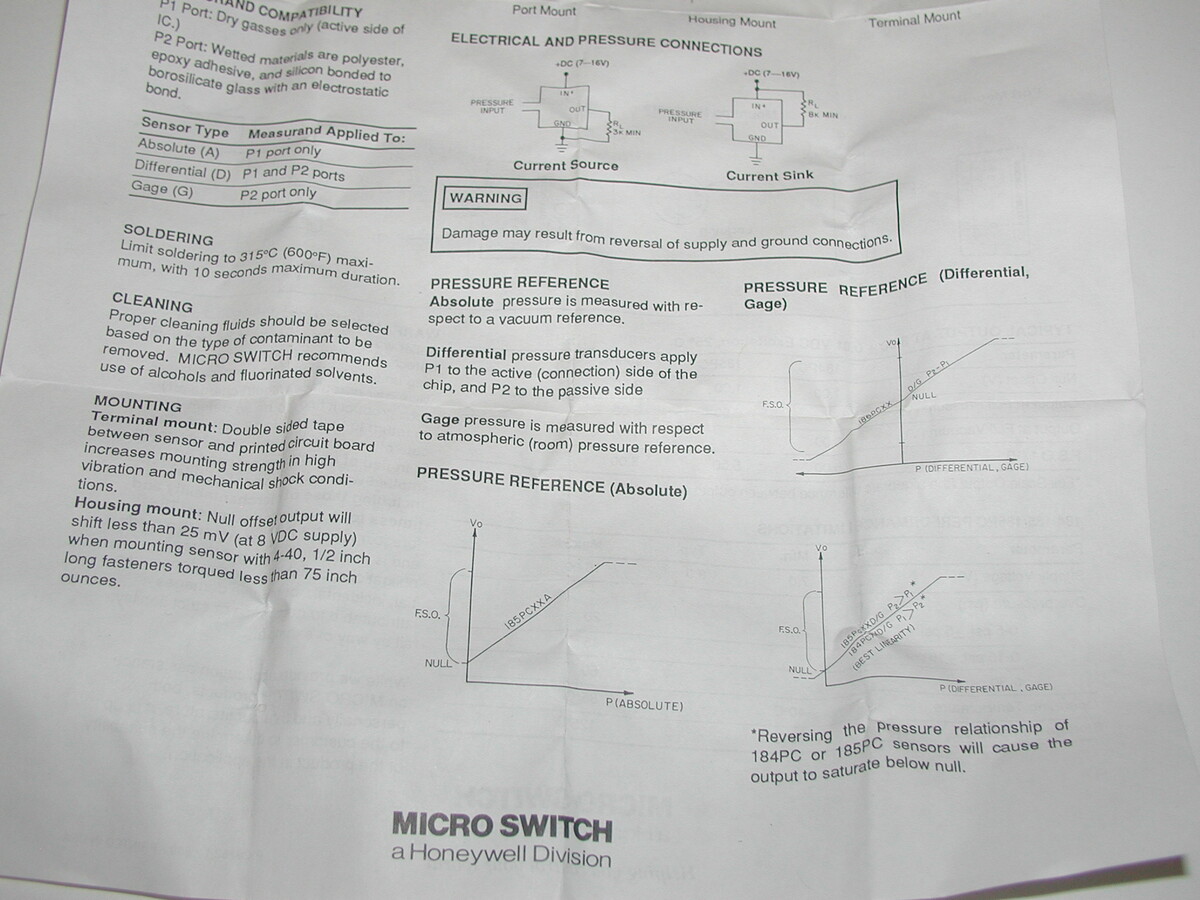
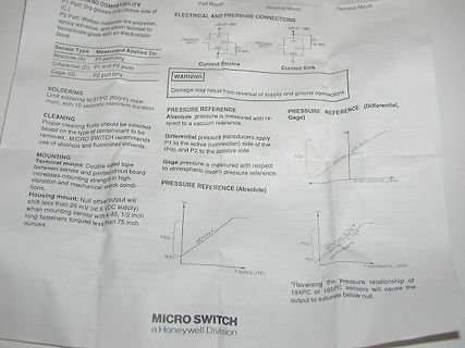
PORT AND COMPATIBILITY P1: Port: Dry gases (only active side of (C.) P2: Port: Wetted materials are polyester, epoxy adhesive, and silicon bonded to a borosilicate glass with an electrostatic bond. ELECTRICAL AND PRESSURE CONNECTIONS PRESSURE INPUT PRESSURE INPUT
-
Thread
IGBT Bauteiltester
kann. Der kann das: https://www.peakelec.co.uk/acatalog/dca75-dca-pro-semiconductor-analyser.html#SID=24 Ist aber inzwischen erschreckend teuer geworden.
-
Thread
Stromzähler Landis E320 -> MommentanLeistung auslesen
Kapitel 3.1 ein Feld 1.6.0 bzw. 2.6.0 geben. Wenn es nach: https://www.ploesch.de/index.php?side=g-smlerklaert geht, wäre das gesuchte Feld wohl eine 10.7.0 Ich habe allerdings nur die im Bild dargestellten Datensätze. Also eine 60.32.01 und eine 60.01.00 Wie sehr ihr das? .....
-
 Bild
Bild
Schaltplan mit Operationsverstärker und Optokopplern
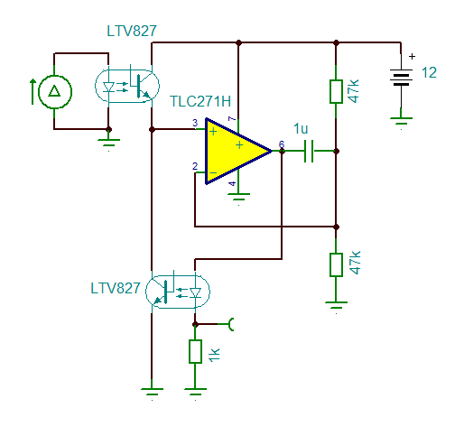
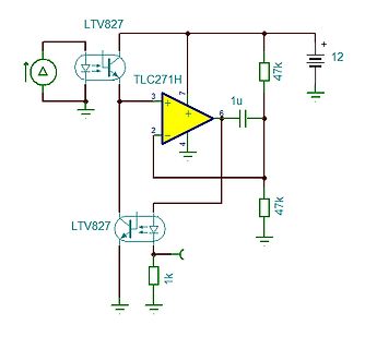
LTV827 TLC271H 1u 47k 12 47k 1k
-
Thread
Probleme mit VCCS
Liebes Forum, ich versuche aktuell, eine high-side VCCS zu bauen. Als Vorlage habe ich mich am Blogeintrag zu "Konstantstromquellen" orientiert. (https://www.mikrocontroller.net/articles/Konstantstromquelle). Mein aktuelles Problem ist, dass ich
-
Thread
Schirmgitter-Spannungsversorgung stabilisieren
stabilisierte 150V wandelt. Konkret dachte ich an einen Minimalaufbau mit TL494 und IR2184 als High-Side-Treiber, die aus der negativen Hilfsspannung (es stehen -50V zur Verfügung) gespeist werden. Als Frequenz würde ich min. 250kHz ansetzen, um oberhalb der Streuspitze des AÜs zu liegen. Das Ganze müsste
-
Thread
Digikey teurer, Vivado unter Jahresabonnement, kostenlose Compiler von Microchip uvam
programmer with UART connection • PowerIO Shield - Extended power capabilities with six 3A high-side switches at up to 48V • Arduino headers - Compatible with a wide range of Arduino shields and accessories [/c] Unter https://mercedes-benz.github.io/ardep/samples/uds/README.html findet sich
-
Thread
[VS] verschenke Creative Kamera VF0800
Internet weiß etwas über Intel RealSense 3D usw https://support.creative.com/kb/ShowArticle.aspx?sid=124661 Ich kann mit dem Ding nichts anfangen, weiß auch nicht ob sie läuft etc. -> Kann die jemand gebrauchen? Versand gegen Porto-Ersatz.
-
Thread
NFC-Jukebox auf Basis einer bestehenden Bluetooth-Box
Wemos gesteuert wird und den Verstärker + Boost-Wandler freischaltet. - Oder ein einzelner High-Side-Switch, der die komplette Last (5 V + Verstärker) steuert. Was wäre hier die sauberste und energieeffizienteste Lösung? Ich freue mich über Tipps zu: - geeigneten Verstärkern (klein, effizient
-
Thread
4GB-Variante des Arduino Uno Q, zweite Version des AI-Hats, diverse ESP32-C5-Boards
bei Seeed öfter) Warum spekulieren? "Support for 3.7V LiPo batteries via two pads on the back side of the board; SGM40567 charging chip" https://www.cnx-software.com/2026/01/16/xiao-esp32-c5-a-tiny-usb-c-iot-board-with-dual-band-wifi-6-bluetooth-5-0-le-zigbee-and-thread-connectivity/
-
Thread
P-Kanal MOSFET/JFET - Wo liegt derzeit max. Ugth und min. Rds_on?
Beitrag #8029985: > aber N-Kanal. Das ist mir bekannt. Für die gibt es auch entsprechende High-Side-Treiber und Erzeugung einer Hilfsspannung. Wegen der besseren Beweglichkeit von Elektronen gegenüber Löchern haben n-Kanal-Halbleiter natürlich einen Vorteil. Der Chip fällt daher für gleiche Leistungen
-
Thread
[V] ältere Bauteile abzugegben
Kanal ADG201 analogschalter 4 fach AD558 D/A Wandler 8bit 1 Kanal MAX472 Precision, High-Side Current-Sense Amplifiers
-
Thread
"Reparatur"-Bericht Samsung TV - RU-Serie - Bootloop wegen CVK-Lines
intensiver werdend (11.jpg); scheinbar haben die 150R da was "rausgebrannt" mit der Linie als side-effect... Fortsetzung folgt...
-
 Bild
Bild
Grafik eines Wireless-Tag Moduls mit Stamp-Hole Design
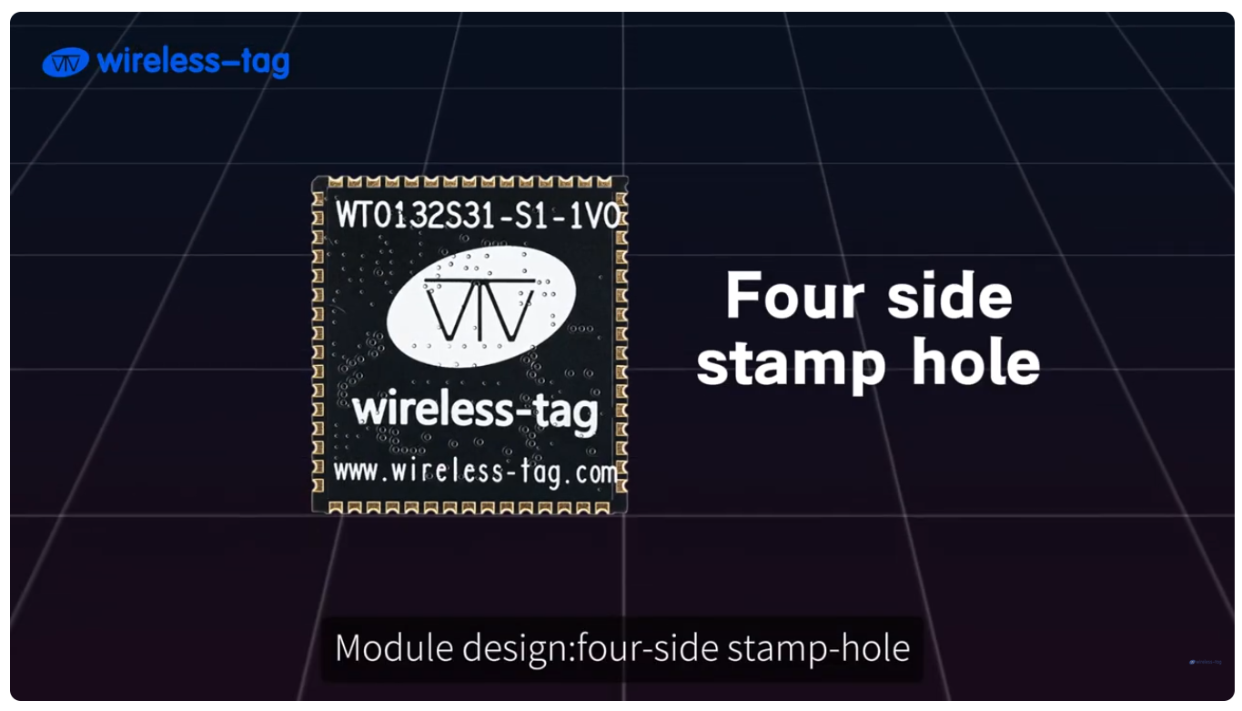
wireless-tag WT0132S31-S1-1V0 Four side stamp hole Module design:four-side stamp-hole www.wireless-tag.com
-
 Bild
Bild
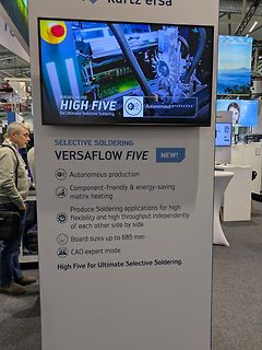
Werbeständer für Versaflow Five Selektives Löten
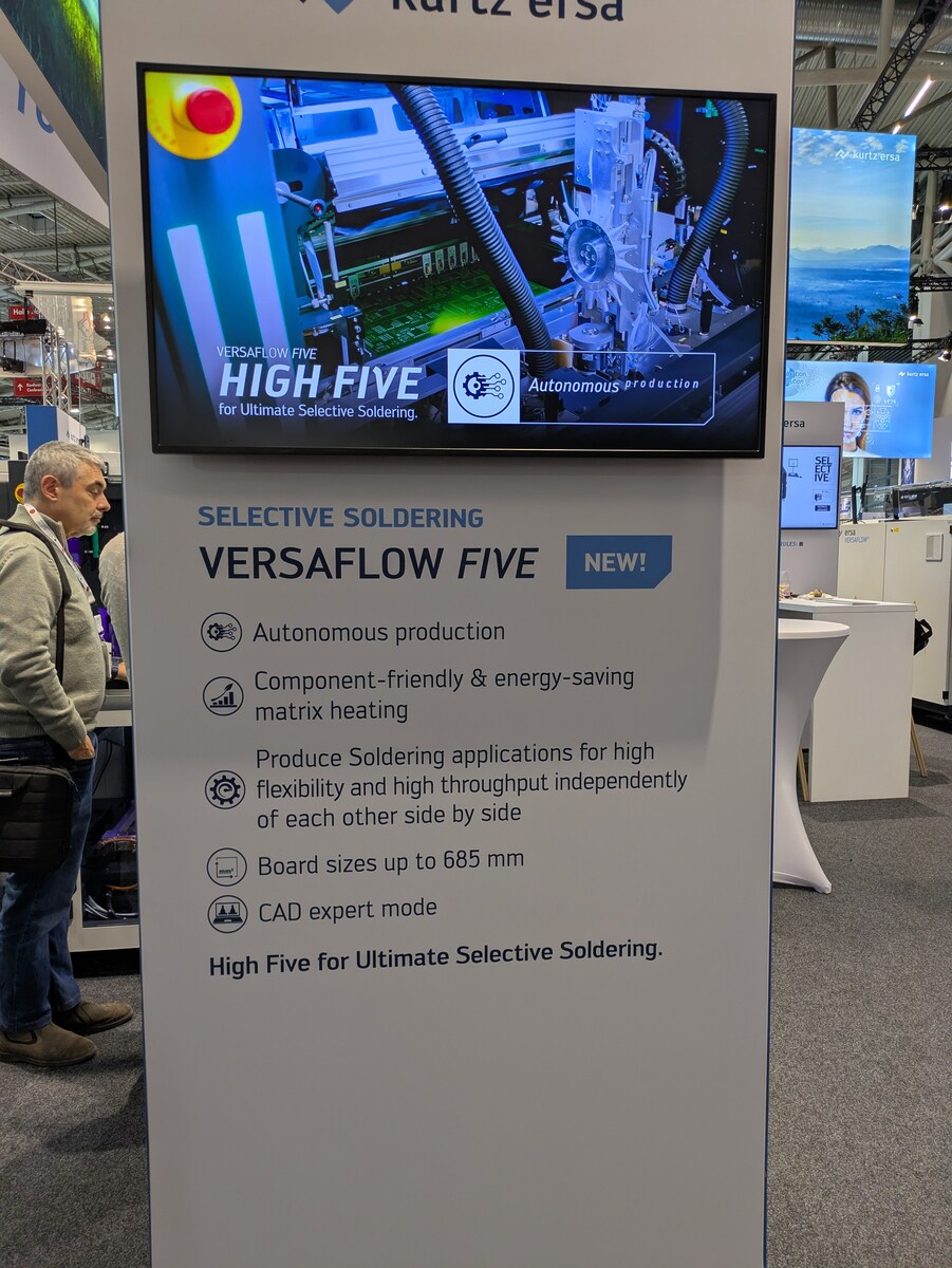
Produce Soldering applications for high flexibility and high throughput independently of each other side by side. Board sizes up to 685 mm. CAD expert mode. High Five for Ultimate Selective Soldering.
-
 Bild
Bild
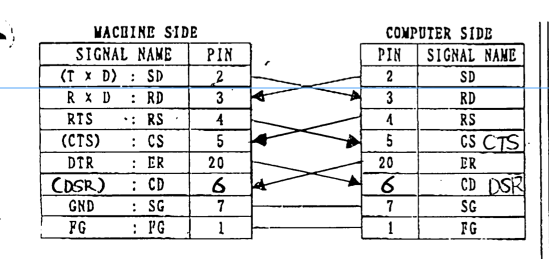
Pinbelegungstabelle RS-232 Verbindung
MACHINE SIDE SIGNAL NAME PIN (T x D) : SD 2 R x D : RD 3 RTS : RS 4 (CTS) : CS 5 DTR : ER 20 (DSR) : CD 6 GND : SG 7 FG : FG 1 COMPUTER SIDE PIN SIGNAL NAME 2 SD 3 RD 4 RS 5 CS CTS 20 ER 6 CD DSR 7 SG 1 FG

-
 Bild
Bild
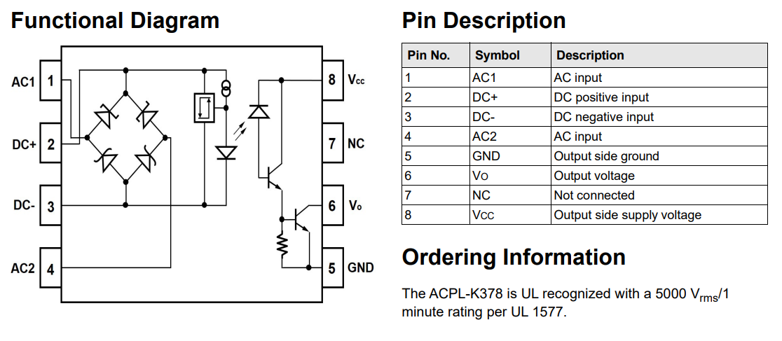
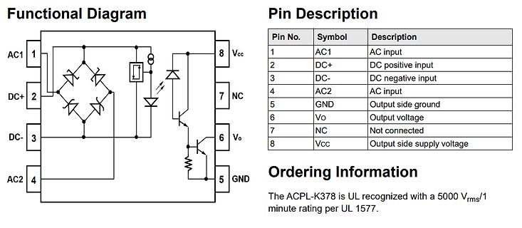
Funktionsdiagramm und Pinbelegung eines Optokopplers
Description 1 AC1 AC input 2 DC+ DC positive input 3 DC- DC negative input 4 AC2 AC input 5 GND Output side ground 6 Vo Output voltage 7 NC Not connected 8 Vcc Output side supply voltage Ordering Information The ACPL-K378 is UL recognized with a 5000 Vrms/1 minute rating per UL 1577.
-
Thread
lokale KI Experiment auf altem (LLM)
Muzzle and Whiskers:** The small, square muzzle has a pink nose. Long, white whiskers extend from the sides of the face, adding texture to the face.\n* **Background:** The background is a soft, out-of-focus green, suggesting the cat is sitting in a garden or outdoors." [/code]
-
 Bild
Bild
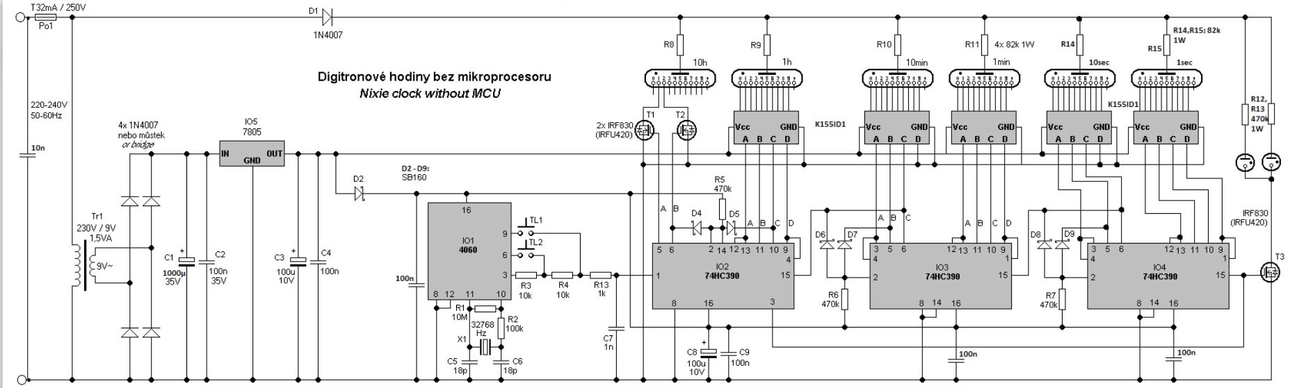
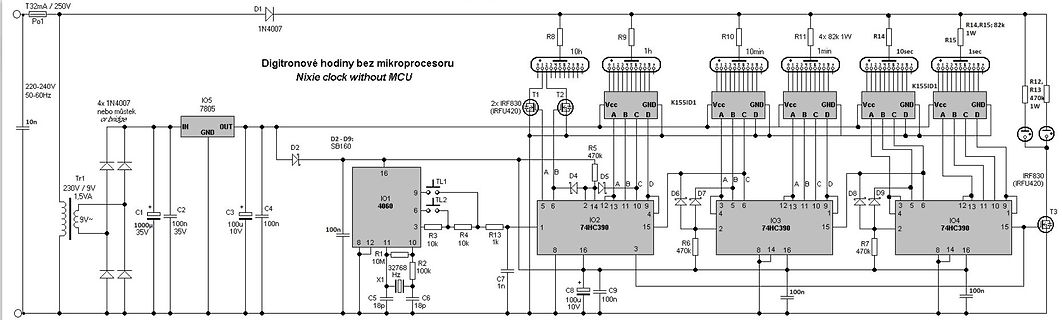
Schaltplan einer Nixie-Uhr ohne Mikrocontroller
1min R11 4x 82 1W R14 10sec R15 1sec R12 R13 470 1W T1 T2 T3 IO2 74HC390 IO3 74HC390 IO4 74HC390 K15SID1 K15SID1 IRF830 IRF420
-
 Bild
Bild
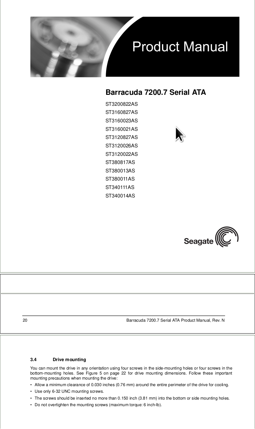
Seagate Barracuda 7200.7 Produktmanual Seite
Manual, Rev. N 3.4 Drive mounting You can mount the drive in any orientation using four screws in the side-mounting holes or four screws in the bottom-mounting holes. See Figure 5 on page 22 for drive mounting dimensions. Follow these important mounting precautions when mounting the drive: • Allow a minimum
-
 Bild
Bild
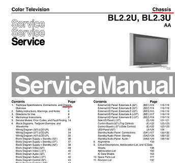
Inhaltsverzeichnis eines Service Manuals für Color Television
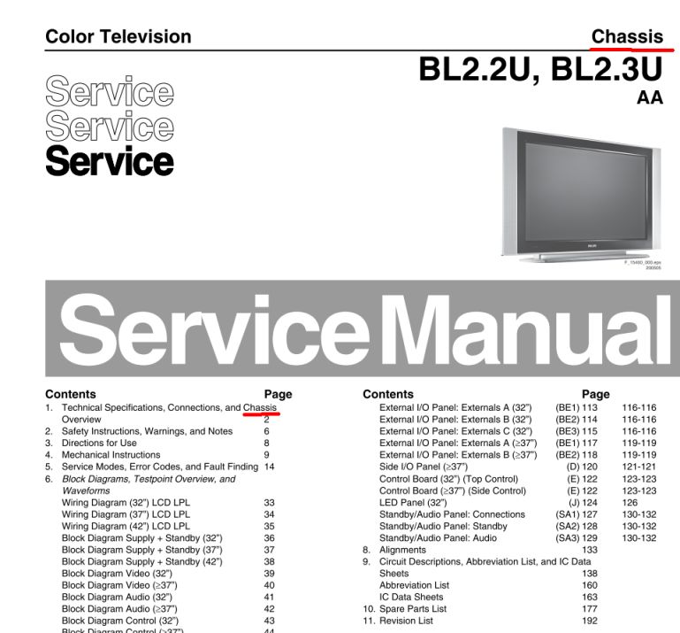
I/O Panel: Externals A (>37") (BE1) 116-119 External I/O Panel: Externals B (>37") (BE2) 119-119 Side I/O Panel (>37") (D) 120 121-121 Control Board (32") (Top Control) (E) 122 123-123 Control Board (>37") (Side Control) (E) 122 123-123 LED Panel (32") (J) 124 126 Standby/Audio Panel: Connections (SA1
-
Thread
[V] SMD-Bauteile auf Tape & Reel (Restmengen / Rollenreste)
5V USB PWR CNTRL SWITCH -40-85C 1400 Littlefuse KSS221G LFS Tactile Switches Subminiature SMT Side Actuated 2000 Maxlinear SP3232EEY-L/TR RS-232 Interface IC TRUE +3V-+5.5V RS-232 1500 Texas Instruments TXS0108EPWR Translation - Voltage Levels 8B Bidir Vltg-Level Translator A 595-TXS A 595