-
Thread
LoRA-Roadmap, neue Messtechnik, OpenNEC und Seitenkanalanalyse
=eyJhbGciOiJFUzI1NiIsImtpZCI6ImFzaWFub21ldHJ5LnBhc3Nwb3J0Lm9ubGluZSIsInR5cCI6IkpXVCJ9.eyJhdWQiOiJhc2lhbm9tZXRyeS5wYXNzcG9ydC5vbmxpbmUiLCJhenAiOiJWRmoyM1ZBZFpESzJNQ1ZYc3VXYTN2IiwiZW50Ijp7InVyaSI6WyJodHRwczovL2FzaWFub21ldHJ5LnBhc3Nwb3J0Lm9ubGluZS9tZW1iZXIvZXBpc29kZS90YWl3YW5zLWRyYW0tZmFpbHVyZSJdfSwiZXhwIjoxNzgyODYwNTQ5LCJpYXQiOjE3ODAyNjg1NDksImlzcyI6Imh0dHBzOi8vYXBwLnBhc3Nwb3J0Lm9ubGluZS9vYXV0aCIsInNjb3BlIjoiZmVlZDpyZWFkIGFydGljbGU6cmVhZCBhc3NldDpyZWFkIGNhdGVnb3J5OnJlYWQgZW50aXRsZW1lbnRzIiwic3ViIjoiMDE5NDg0NjEtZjA2NC03NWE0LWE0YjktOTFjM2E4ZTMyOGVjIiwidXNlIjoiYWNjZXNzIn0.UrrD13kOHo79VRTRza5bbwJgjq26wZt63gTbA6OzMoAbg4tDqD5-WLKUAAI_lMRDE9NI2vtKk-5PEEDs1vsTbQ findet sich - ein bei Beibehaltung des Access-Tokens kostenlos lesbarer - Artikel, der die „Abenteuer“ der in Taiwan ansässigen
-
 Bild
Bild
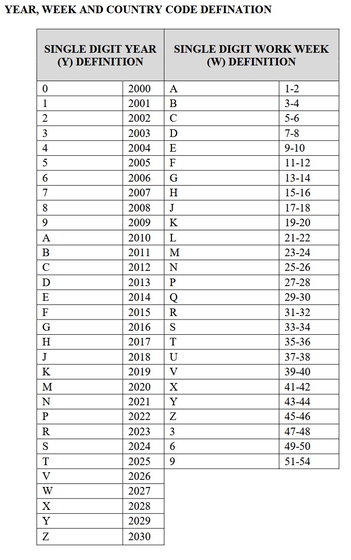
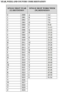
Tabelle zur Definition von Jahr, Woche und Ländercode
YEAR, WEEK AND COUNTRY CODE DEFINATION SINGLE DIGIT YEAR (Y) DEFINITION SINGLE DIGIT WORK WEEK (W) DEFINITION 0 2000 A 1-2 1 2001 B 3-4 2 2002 C 5-6 3 2003 D 7-8 4 2004 E 9-10 5 2005 F 11-12 6 2006 G 13-14 7 2007 H 15-16 8 2008 J 17-18 9 2009 K 19-20 A 2010 L 21-22 B 2011 M 23-24 C 2012 N 25-26 D 2013 P 27-28 E 2014 Q 29-30 F 2015 R 31-32 G 2016 S 33-34 H 2017 T 35-36 J 2018 U 37-38 K 2019 V 39-40 M 2020 X 41-42 N 2021 Y 43-44 P 2022 Z 45-46 R 2023 3 47-48 S 2024 6 49-50 T 2025 9 51-54 V 2026 W 2027 X 2028 Y 2029 Z 2030
-
 Bild
Bild
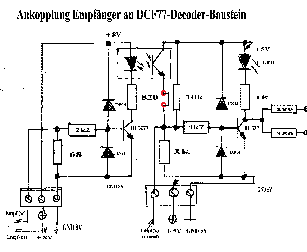
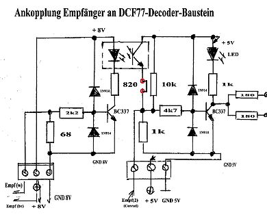
Schaltplan zur Ankopplung eines Empfängers an DCF77-Decoder
Ankopplung Empfänger an DCF77-Decoder-Baustein + 8V LED 820 10k + 5V 1k 1N914 4k7 BC337 180 180 1N914 1k BC337 1N914 2k2 68 Empf (w) GND 8V Empf (br) + 8V GND 5V Empf(2) (Conrad) + 5V GND 5V
-
 Bild
Bild
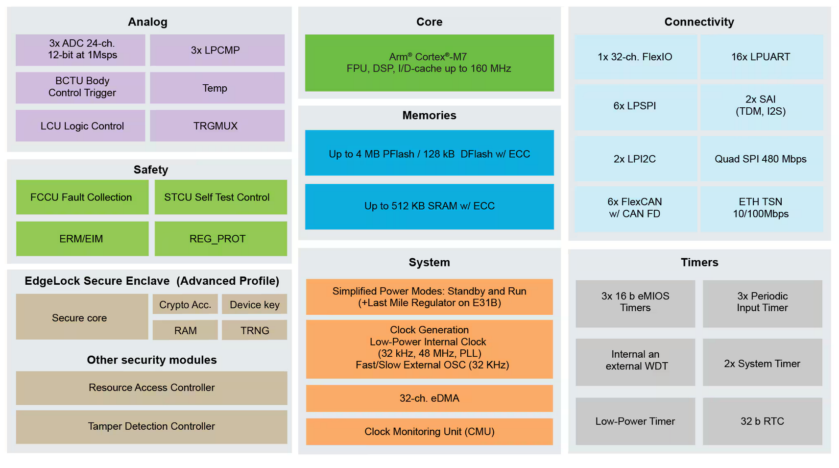
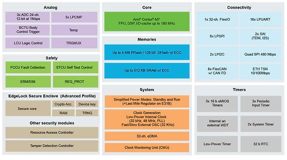
Blockschaltbild eines Mikrocontrollers
Cortex-M7, FPU, DSP, I/D-cache up to 160 MHz. Connectivity: 1x 32-ch. FlexIO, 16x LPUART, 6x LPSPI, 2x SAI (TDM, I2S), 2x LPI2C, Quad SPI 480 Mbps, 6x FlexCAN w/ CAN FD, ETH TSN 10/100Mbps. Memories: Up to 4 MB Pflash / 128 kB DFlash w/ ECC, Up to 512 KB SRAM w/ ECC. Safety: FCCU Fault Collection, STCU
-
 Bild
Bild
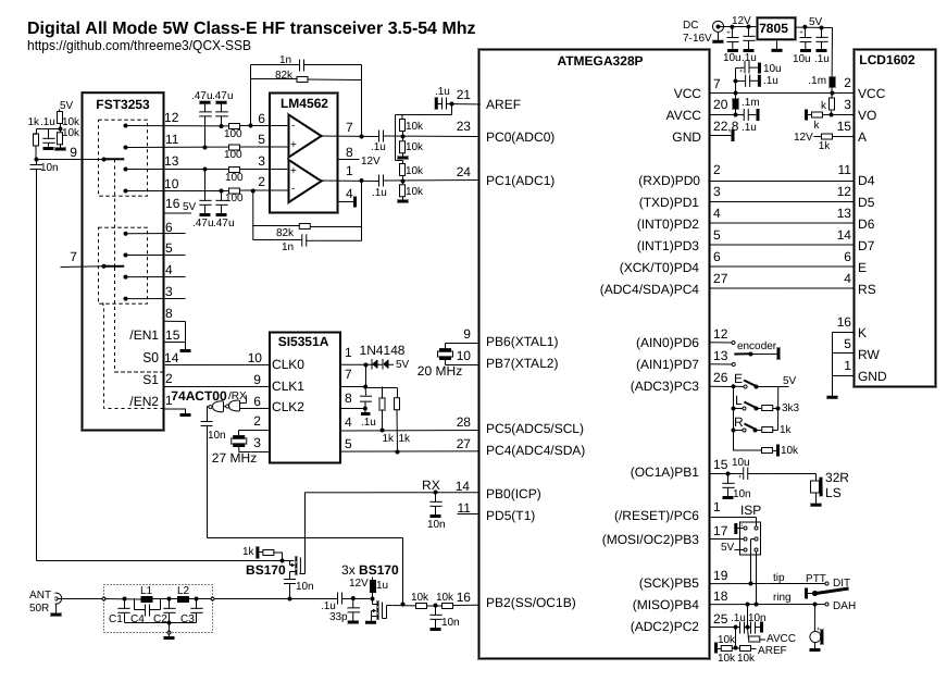
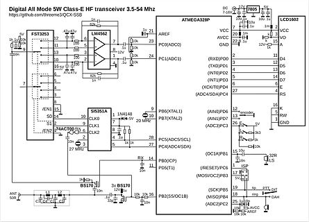
Schaltplan eines 5W HF-Transceivers
Digital All Mode 5W Class-E HF transceiver 3.5-4 MHz FST2357, LM4562, ATMEGA328P, LCD1602, SI5351A, 74ACT0, 7805, 27 MHz, 20 MHz, 5V, 12V, 10k, 1u, 47u, 82k, 3p, 1k, 3k3, ANT, 50R, L1, L2, C1, C4, C2, C3, BS170, PB2, PB0, PD5, PB3, PC2, SCK, MISO, PTT, DIT, DAH, RESET, ICP, MOSI, OC2, SS, OC1B, ADC2, PC4, SDA, PC5, SCL, OC1A, PB1, ADC3, PC3, AIN1, PD7, AIN0, PB6, XTAL1, PB7, XTAL2, INT1, PD3, XCK, PD4, ADC4, PC1, RXD, TXD, D4, D5,
-
 Bild
Bild
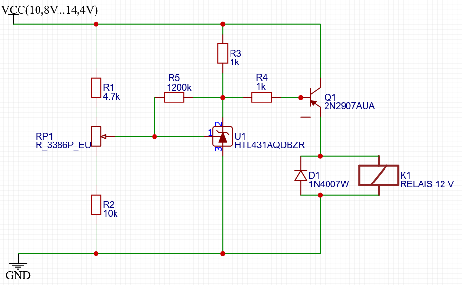
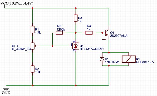
Schaltplan einer Relaissteuerung mit Shunt-Regler
VCC(10,8V...14,4V) R1 4.7k R2 10k R3 1k R4 1k R5 1200k RP1 R_3386P_EU U1 HTL431AQDBZR Q1 2N2907AUA D1 1N4007W K1 RELAIS 12 V GND
-
 Bild
Bild
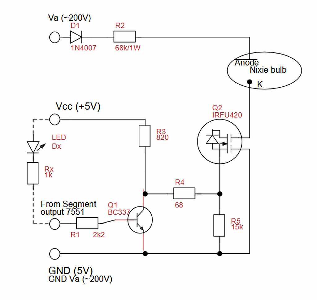
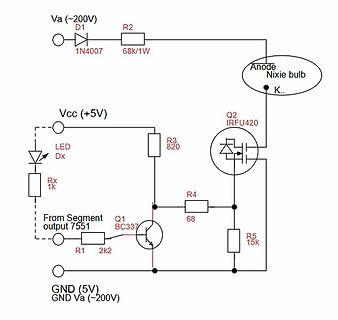
Schaltplan einer Nixie-Röhren-Ansteuerung
Va (~200V) D1 1N4007 R2 68k/1W Anode Nixie bulb K.. Vcc (+5V) LED Dx R3 820 Q2 IRFU420 R4 68 R5 15k Q1 BC337 R1 2k2 From Segment output 751 GND (5V) GND Va (~200V)
-
 Bild
Bild
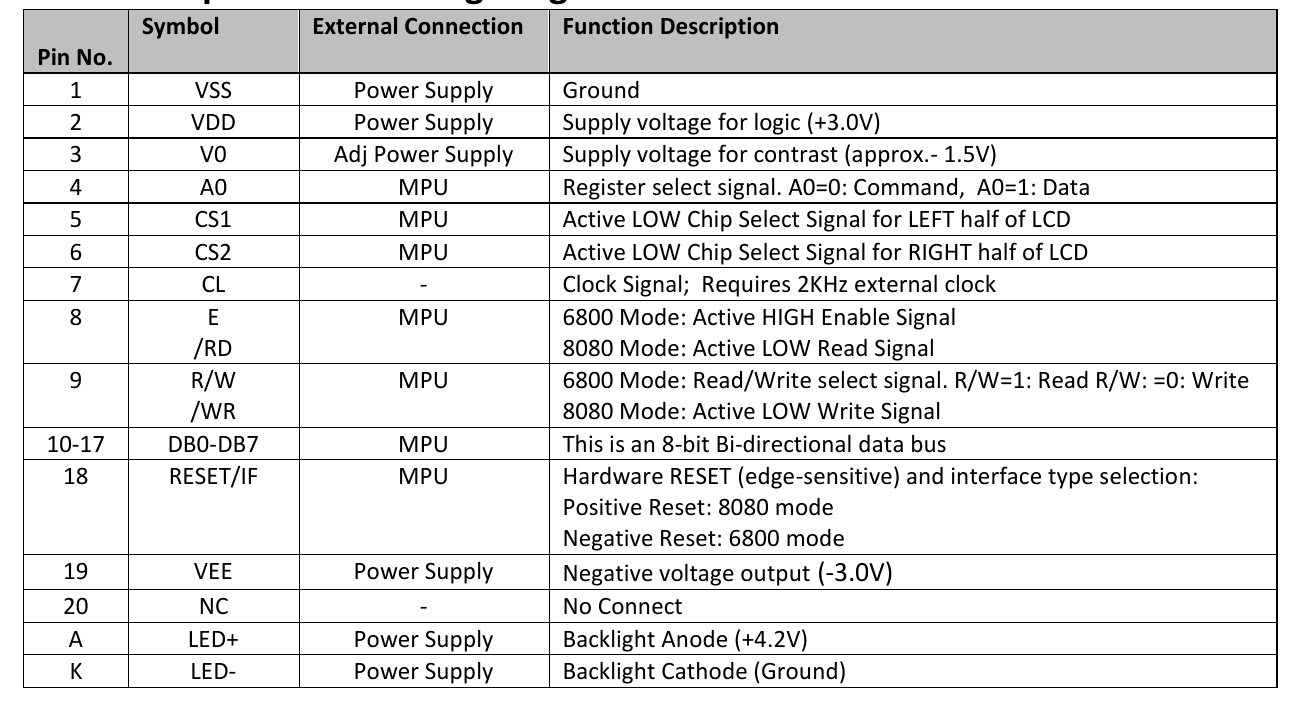
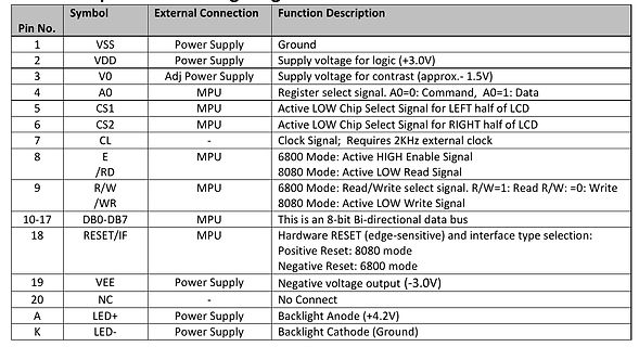
Pinbelegungstabelle eines LCD-Displays
Select Signal for LEFT half of LCD 6 CS2 MPU Active LOW Chip Select Signal for RIGHT half of LCD 7 CL CL Signal; Requires 2KHz external clock 8 E MPU 6800 Mode: Active HIGH Enable Signal 9 /RD R/W 8080 Mode: Active LOW Read Signal /RW 6800
-
Thread
[V] HUBER+SUHNER HF-Blitz-/Überspannungsschutz für Außenantennen - Typ: 3G-ACC-OUT-LA
integriertem Hochpassfilter Frequenzbereich: 800–2200 MHz Impedanz: 50 Ohm maximale HF-Leistung: 20 W Einfügedämpfung: max. 0,2 dB VSWR: < 1,22:1 Anschlüsse: TNC Male / TNC Female Überspannungsschutz laut Hersteller: bis 10 kA Einzelimpuls / 5 kA bei mehreren Impulsen für Außenantennen / Mobilfunk
-
 Bild
Bild
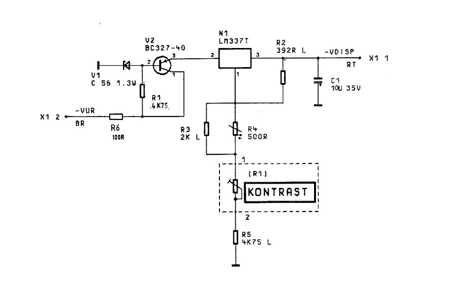
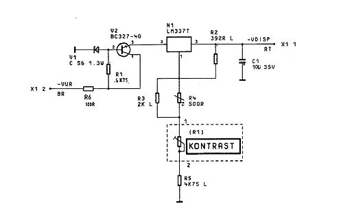
Schaltplan einer Spannungsregelung mit LM37T
V2 BC327-40 3 2 R2 392R L -VDISP X1 1 N1 LM337T 3 2 1 V1 C 56 1.3W R1 .4K75 2 X1 2 VUR BR R6 100R R3 2K L R4 50R C1 10U 35V (R1) KONTRAST 1 2 R5 4K75 L
-
 Bild
Bild
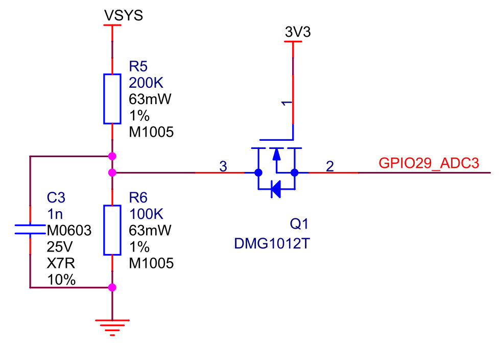
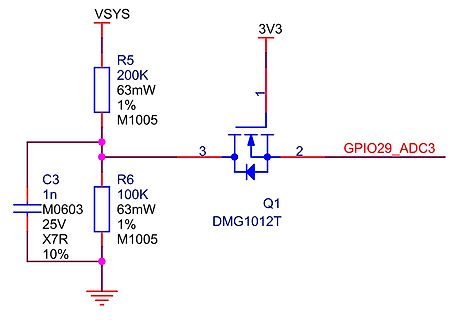
Schaltplan eines MOSFET-Schaltkreises
VSYS R5 200K 63mW 1% M1005 3V3 1 3 2 GPIO29_ADC3 Q1 DMG1012T C3 1n M0603 25V X7R 10% R6 100K 63mW 1% M1005
-
 Bild
Bild
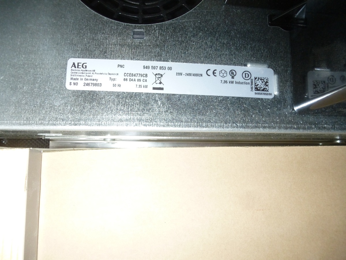
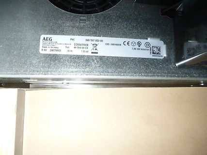
Typenschild eines AEG Induktionskochfelds
616 Kronsberg, Germany Made in Germany S NO 24679803 PNC 949 597 853 00 Typ: 66 D4A 05 CA 50 Hz 7,35 kW 220V-240V/400V2N 7,35 kW Induction 24679803 949597853/00
-
 Bild
Bild
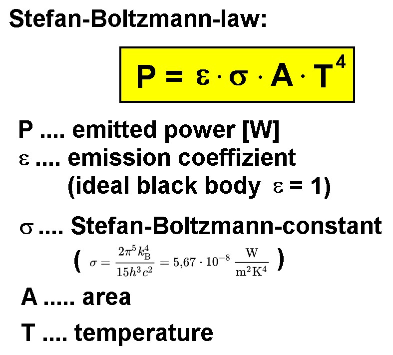
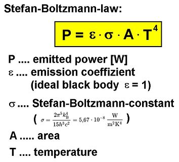
Darstellung des Stefan-Boltzmann-Gesetzes
Stefan-Boltzmann-law: P = ε · σ · A · T⁴ P .... emitted power [W] ε .... emission coeffizient (ideal black body ε = 1) σ .... Stefan-Boltzmann-constant (σ = 2π⁵k_B⁴ / 15h³c² = 5,67 · 10⁻⁸ W/m²K⁴) A .... area T .... temperature
-
Thread
Eine Weihnachtsgeschichte von Frederick Forsyth
Al Maitland. Zumindest ich finde sie immer wieder hörenswert: https://www.youtube.com/watch?v=dV2-Wb0w-8k "A nice, high-quality recording of "Fireside Al" Maitland reading Frederick Forsyth's "The Shepherd" as heard traditionally on "As it Happens" on CBC every Christmas eve beginning in 1979"
-
Thread
AVaRice DebugWire Breakpoints
Ich kann mit 1. avrdude das Binary auf den Controller flashen und die DebugWire Fuse programmieren 2. avarice eine Debug-Session starten 3. avr-gdb durch das Programm steppen und breakpoints setzen Ich habe mehrere Probleme: 1. Breakpoints werden ignoriert 2. Continue-Befehl stoppt nicht mehr,
Das sind die Kommandozeilen die ich nutze: [code] # Debug wire einschalten avrdude -v -c jtag2isp -p at90usb162 -U hfuse:w:0x59:m # Versorgung DUT aus und wieder ein # Debug-Server starten avarice -vvvv --debug --mkII --debugwire --ignore-intr --jtag usb --part at90usb162 :4242 # Debug-Client
-
Artikel
AVR-GCC-Tutorial
Zweifel hilft ein Blick ins Datenblatt ("Interrupt Vectors"). Register. Der AT90S2313 verfügt über 2 Register die mit den Interrupts zusammenhängen. GIMSK General Interrupt Mask Register. Bit 7 6 5 4 3 2 1 0 Name INT1 INT0 - - - - - - R/W R/W R/W R R R R R R Initialwert 0 0 0 0 0 0 0 0 INT1 (External
Register. Das MCU Control Register enthält Kontrollbits für allgemeine MCU-Funktionen. Bit 7 6 5 4 3 2 1 0 Name - - SE SM ISC11 ISC10 ISC01 ISC00 R/W R R R/W R/W R/W R/W R/W R/W Initialwert 0 0 0 0 0 0 0 0 SE (Sleep Enable) Dieses Bit muss gesetzt sein, um den Controller mit dem SLEEP-Befehl in den Schlafzustand
-
 Bild
Bild
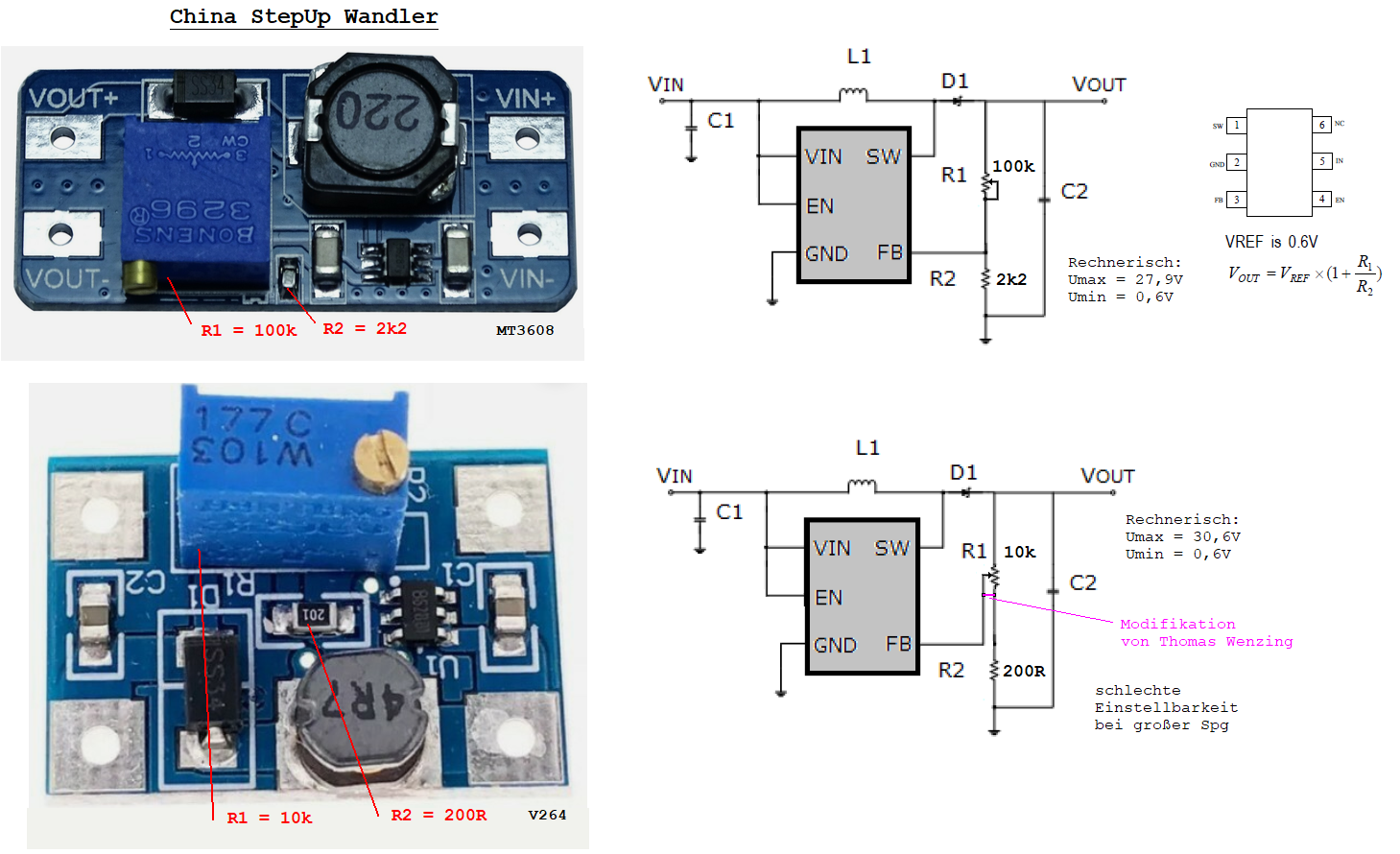
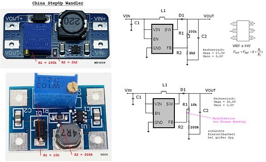
Fotos und Schaltpläne eines MT3608 Step-Up Wandlers
China StepUp Wandler VIN+ VOUT+ L1 D1 C1 VIN SW R1 100k C2 VOUT R2 2k2 Umax = 27,9V Umin = 0,6V VREF = 0,6V VOUT = VREF * (1 + R1/R2) MT3608 177 C W103 C1 R1 10k R2 200R Umax = 30,6V Umin = 0,6V Modifikation von Thomas Wenzing schlechte Einstellbarkeit bei
-
 Bild
Bild
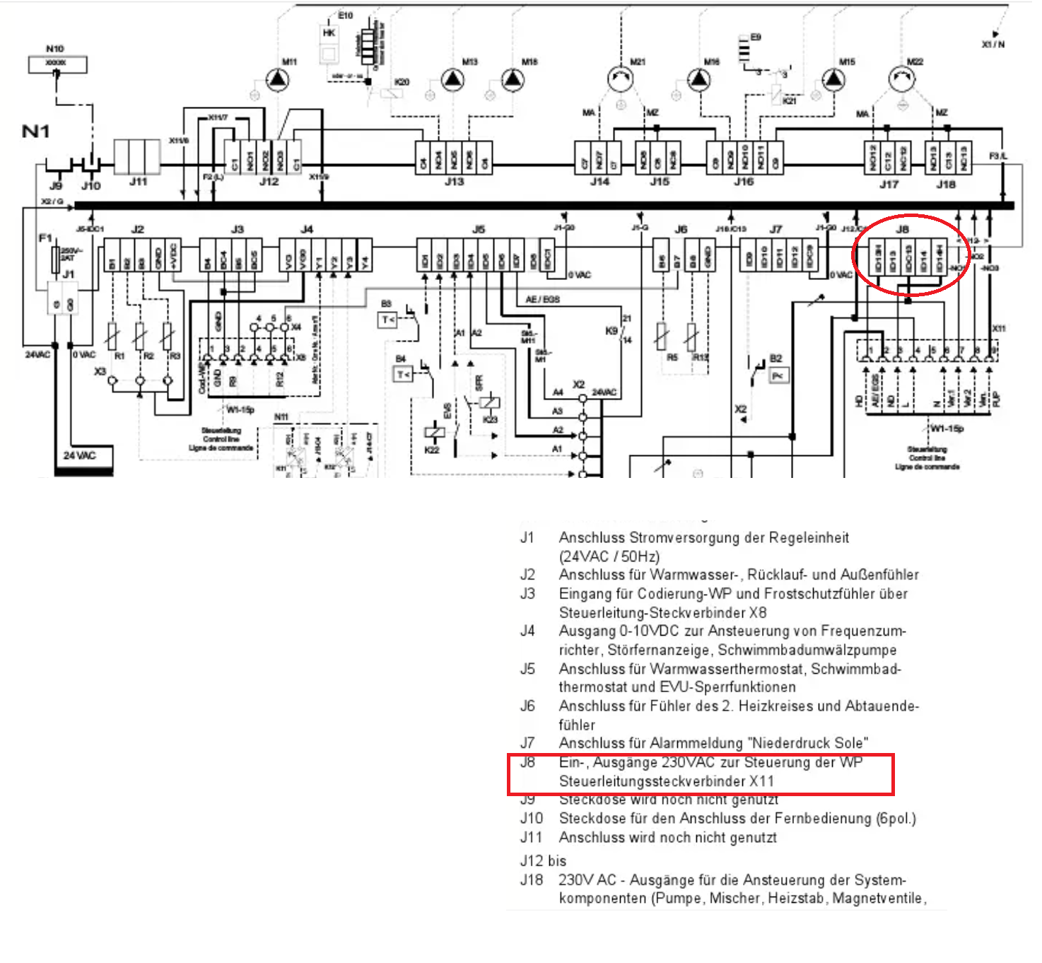
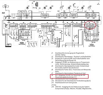
Schaltplan mit Bauteilliste
N10, N1, X1/7, J10, J11, J12, J13, J14, J15, J16, J17, J18, M11, M13, M18, M21, M16, M15, M02, X1/N, K20, MA, MZ, K21, MA, MZ, J19, J-G, J18, J17, J16, C15, J8, C14, C13, C12, C11, C10, C9, C8, C7, C6, C5, C4, C3, C2, C1, J1, 24VAC, 0VAC, 5VAC, 230VAC, W1-15p, W1-15p, J1 bis J18 Liste
-
 Bild
Bild
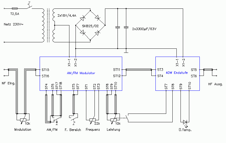
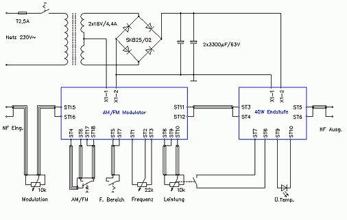
Schaltplan eines AM/FM Modulators und Endstufen-Netzteils
T2,5A, 2x18V/4,4A, SKB25/02, 2x3300µF/63V, ST15, ST16, X1-1, X1-2, AM/FM Modulator, ST11, ST12, ST3, ST4, 40W Endstufe, X1-1, X1-2, ST5, ST6, HF Ausg., ST4, ST8, ST7, ST1B, ST5, ST7, ST2, ST3, ST8, ST10, ST7, ST8, ST9, ST10, NF Eing., Modulation, 10k, AM/FM, F. Bereich, Frequenz, Leistung, 22k, 10k, U.Temp.
-
 Bild
Bild
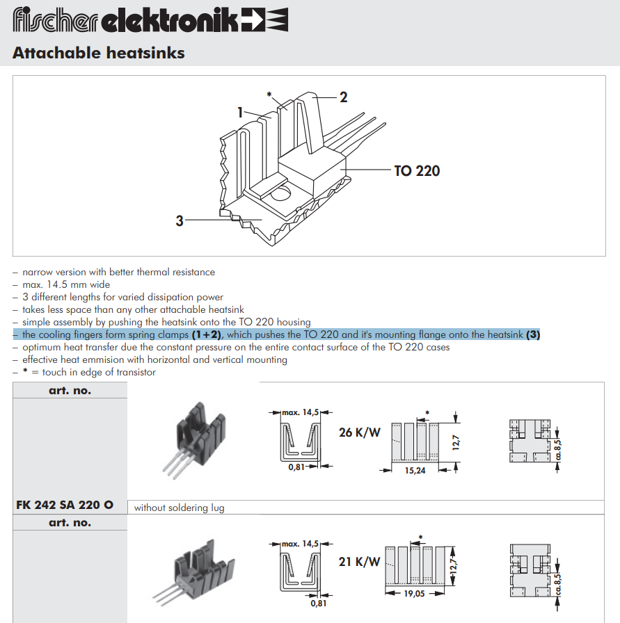
Datenblatt für ansteckbare Kühlkörper
fischer elektronik Attachable heatsinks 1 2 3 TO 220 * - narrow version with better thermal resistance - max. 14,5 mm wide - 3 different lengths for varied dissipation power - takes less space than any other attachable heatsink - simple assembly

-
 Bild
Bild
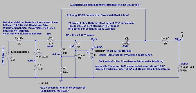
Schaltplan einer Batterieladeschaltung mit Shuntregler
Ausgleich Selbstentladung Motorradbatterie mit Shuntregler Achtung, R3/R2 entladen bei Stromausfall mit 0.4mA! T1 erreicht ohne Batterie, also Leerlauf 60°C auf meinem Testboard. Das geht also noch in Ordnung! Im Betrieb der Schaltung ist es weniger! R3 = 22k + 4.7k Trimmer 13.4V 15V/1A Netzteil F2, 1A 1R D2 33R 46mA 0.4mA 1.8mA NSCW100 R5 6.8k R1 1mA 1k S 24.8mA G TL431 U1 T1 FDC638P T1 ist bei BSP316 Jeder P-Channel der 1W abkann sollte gehen. D 13.1V 1N5817 SS16 F1, 1A 1R Bei Leerlauf/voller
-
 Bild
Bild
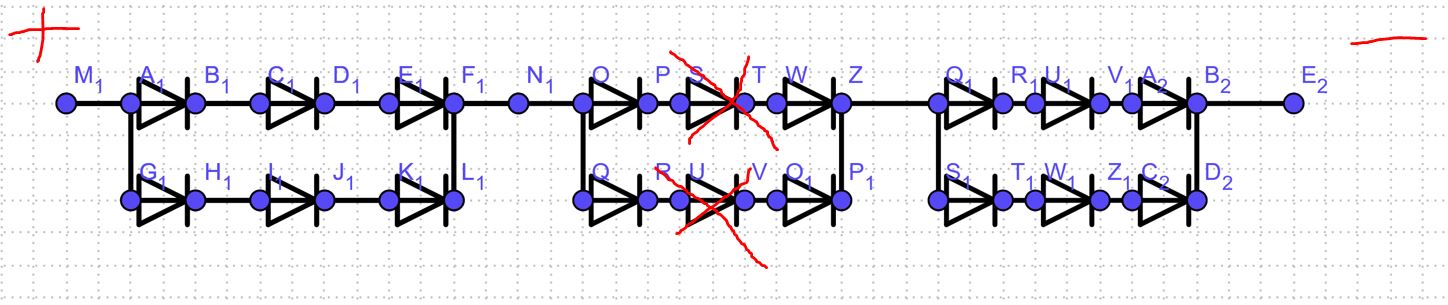
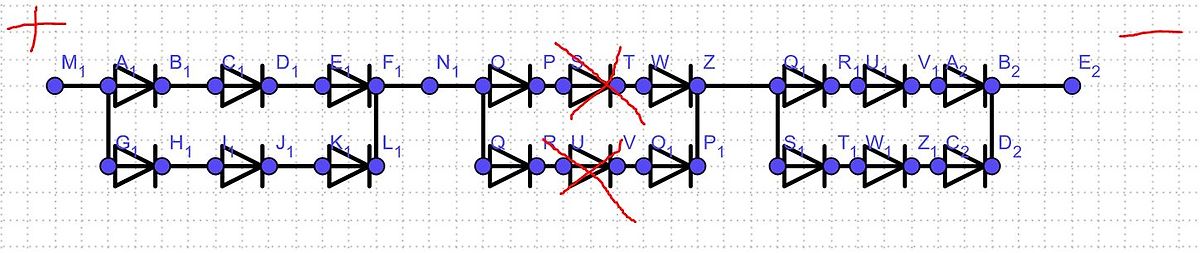
Schaltplan einer Brückengleichrichtung mit Dioden
M1 A1 B1 C1 D1 E1 F1 N1 O1 P1 S1 T1 W1 Z1 Q1 R1 U1 V1 A2 B2 E2 G1 H1 I1 J1 K1 L1 Q2 R2 U2 V2 Q2 P1 S2 T2 W2 Z2 C2 D2
-
 Bild
Bild
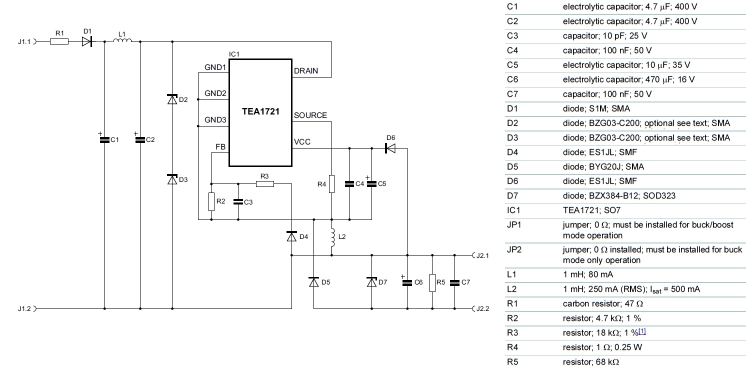
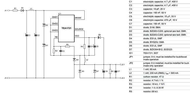
Schaltplan eines TEA1721-basierten Netzteils
mode operation JP2 jumper; 0 Ohm; must be installed for buck mode only operation L1 1 mH; 80 mA L2 1 mH; 250 mA (RMS); Isat = 500 mA R1 carbon resistor; 47 Ohm R2 resistor; 4.7 kOhm; 1% R3 resistor; 18 kOhm; 1% R4 1 Ohm; 0.25 W R5 resistor; 68 kOhm
-
 Bild
Bild
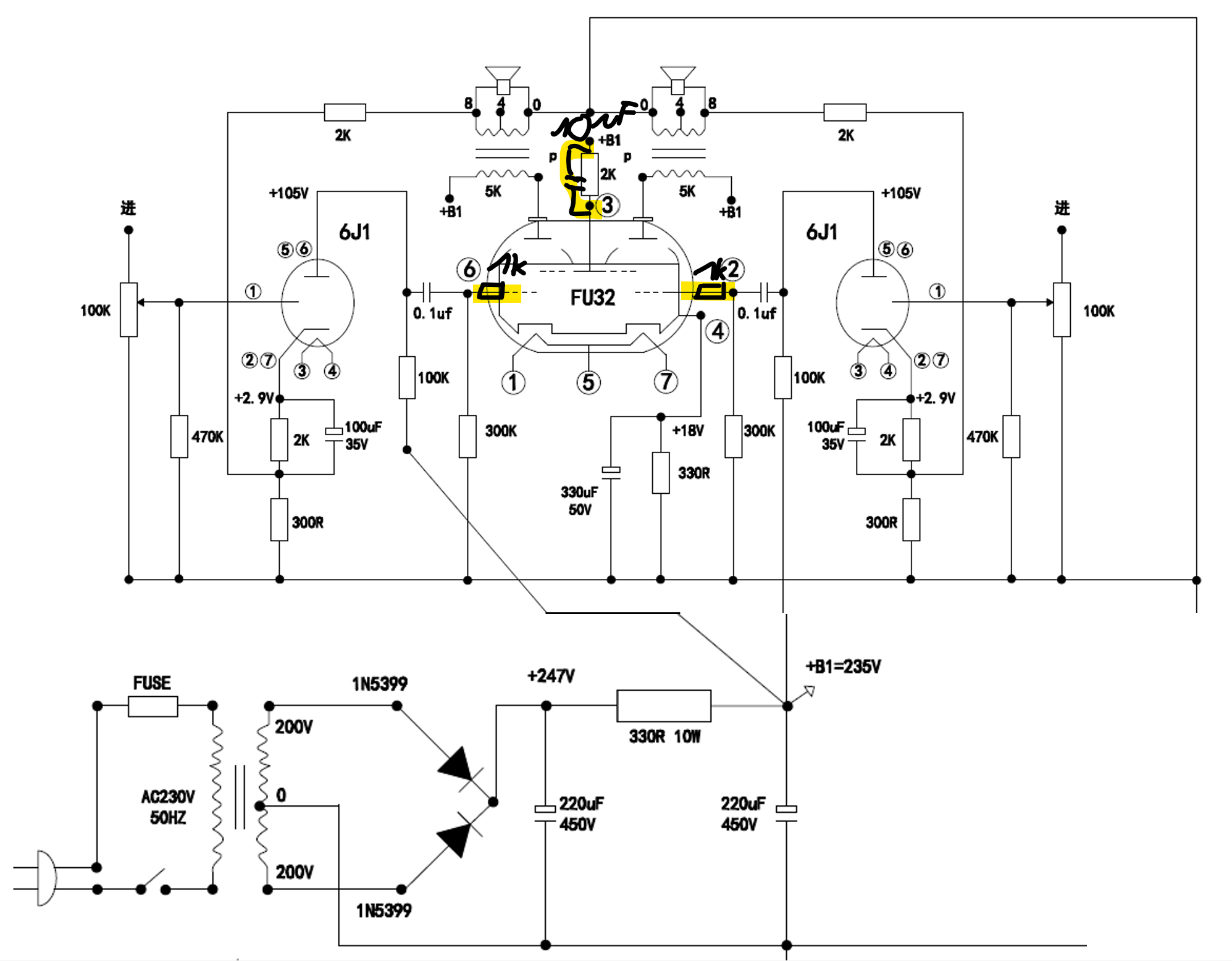
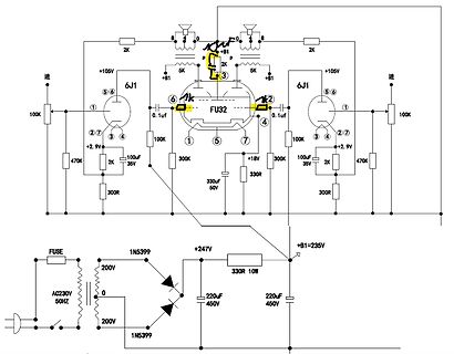
Schaltplan eines Röhrenverstärkers mit Netzteil
6J1, 0.1uf, 100K, 470K, 2K, 300K, 330uF 50V, 300R, +105V, +B1, +2.9V, +18V, +B1=235V, 1N5399, 200V, 220uF 450V, 330R 10W, AC230V 50HZ, FU32
-
 Bild
Bild
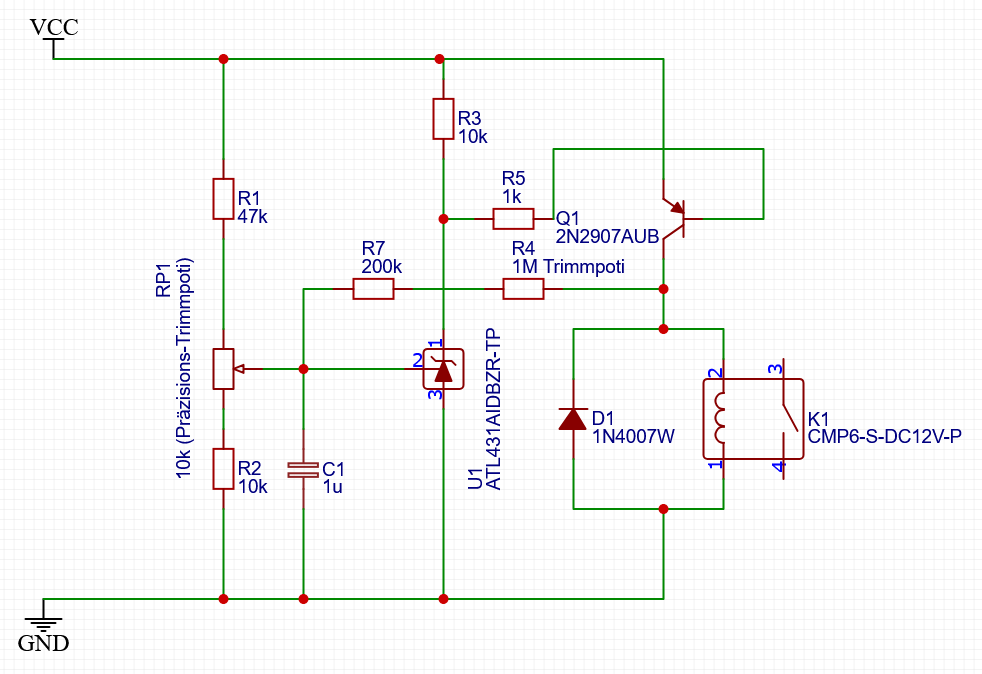
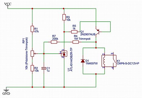
Schaltplan einer Konstantstromquelle mit Relaissteuerung
VCC R3 10k R1 47k R5 1k Q1 2N2907AUB R7 200k R4 1M Trimmpoti RP1 10k Präzisions-Trimmpoti U1 ATL431AIDBZR-TP C1 1u D1 1N4007W K1 CMP6-S-DC12V-P GND
-
 Bild
Bild
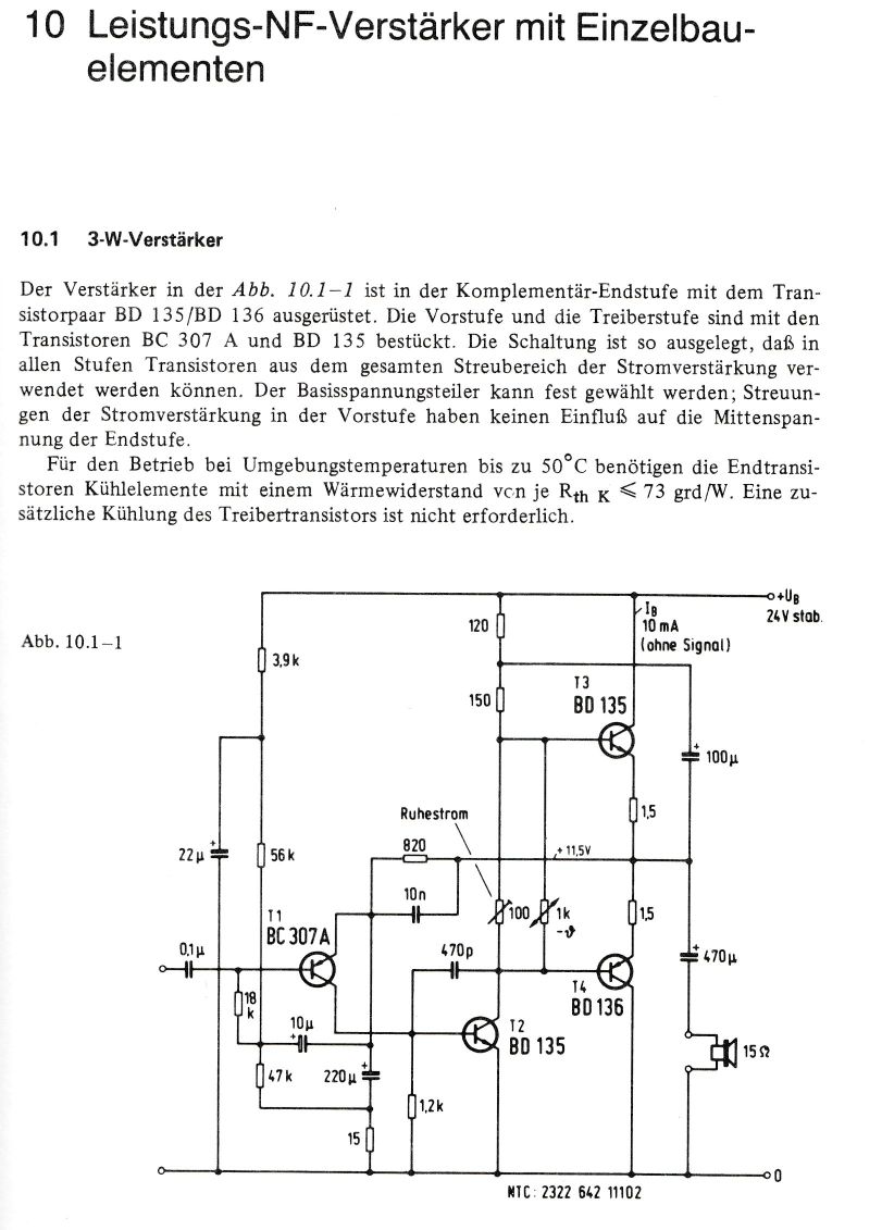
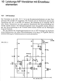
Schaltplan eines 3-W-Leistungsverstärkers
10 Leistungs-NF-Verstärker mit Einzelbauelementen 10.1 3-W-Verstärker BD 135/BD 136 BC 307 A und BD 135 Abb. 10.1-1 3,9 k 22 µ 0,1 µ 18 k 56 k 11 BC 307A 10 µ 47 k 220 µ 1,2 k 15 Ω 0 12 BD 135 14 BD 136 15 Ω 470 µ 1,5 1,5 100 1k 10n 820 150 120 Ia 10 mA +Ub
-
 Bild
Bild
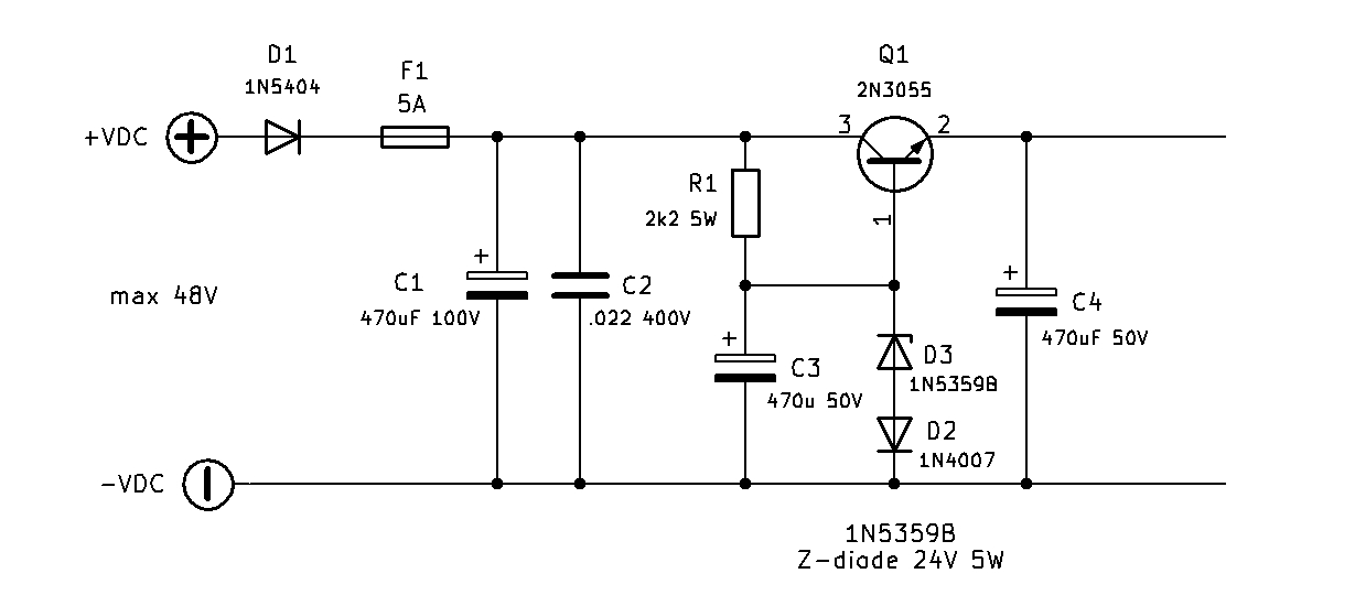
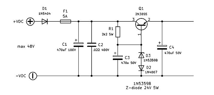
Schaltplan einer Spannungsregelung mit Transistor
D1 1N5404 F1 5A +VDC max 48V C1 470uF 100V C2 .022 400V R1 2k2 5W Q1 2N3055 3 2 1 C3 470u 50V D3 1N5359B C4 470uF 50V D2 1N4007 -VDC 1N5359B Z-diode 24V 5W
-
 Bild
Bild
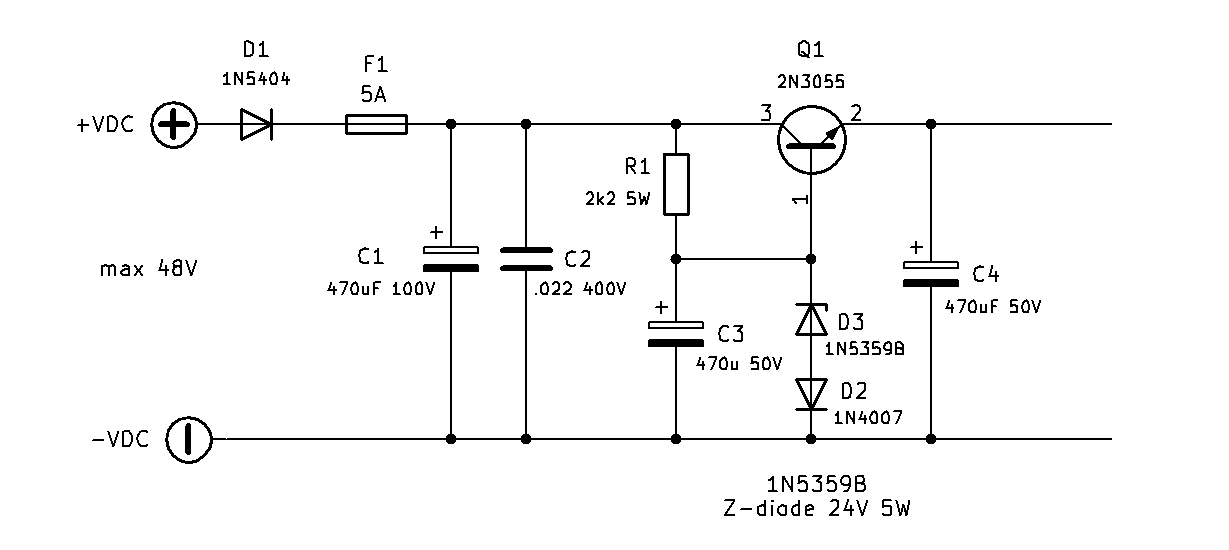
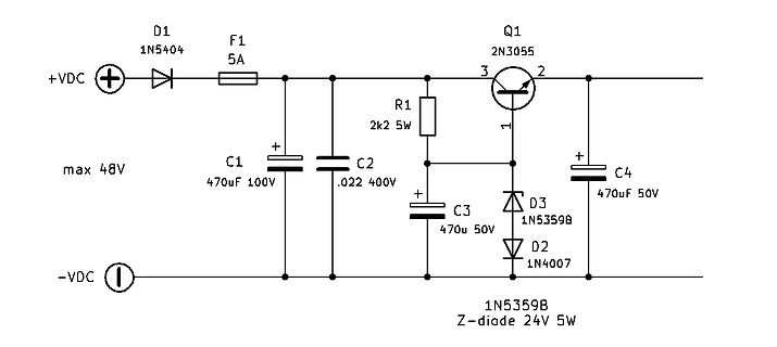
Schaltplan einer Spannungsregelung mit Transistor
D1 1N5404 F1 5A +VDC max 48V C1 470uF 100V C2 .022 400V R1 2k2 5W Q1 2N3055 3 2 1 C3 470u 50V D3 1N5359B C4 470uF 50V D2 1N4007 -VDC 1N5359B Z-diode 24V 5W
-
 Bild
Bild
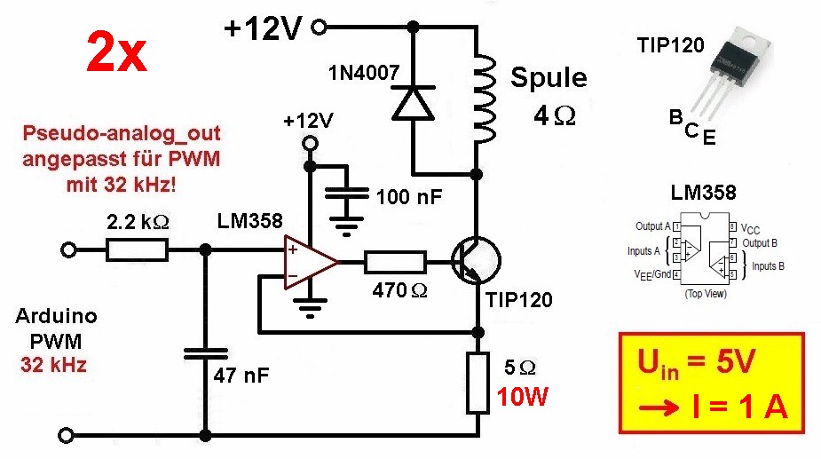
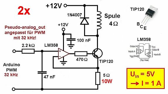
Schaltplan einer PWM-gesteuerten Last mit LM358 und TIP120
2x Pseudo-analog_out angepasst für PWM mit 32 kHz! +12V 1N4007 Spule 4Ω TIP120 BCE +12V 100 nF LM358 2.2 kΩ 47 nF Arduino PWM 32 kHz 470 Ω TIP120 5Ω 10W Uin = 5V -> I = 1 A
-
 Bild
Bild
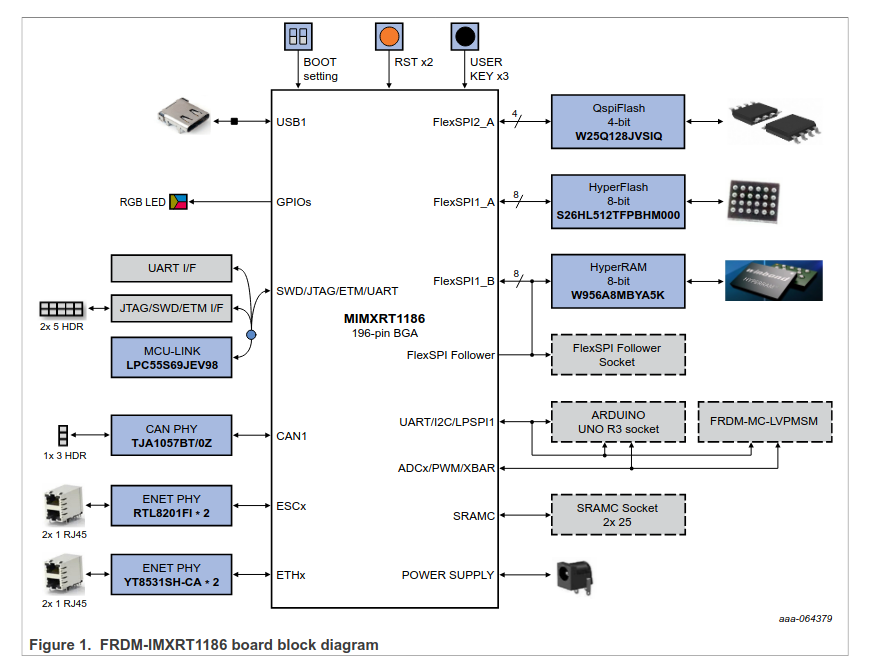
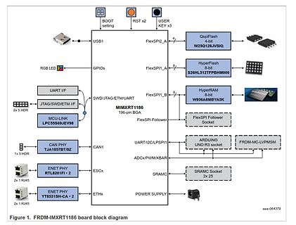
Blockschaltbild des FRDM-IMXRT1186 Boards
BOOT setting, RST x2, USER KEY x3, QspiFlash 4-bit W25Q128JVSIQ, RGB LED, GPIOs, FlexSPI2_A, HyperFlash 8-bit S26HL512TFPBHM000, FlexSPI1_A, 2x5 HDR, JTAG/SWD/ETM I/F, MIMXRT1186 196-pin BGA, FlexSPI1_B, HyperRAM 8-bit W956A8MBYA5K
-
 Bild
Bild
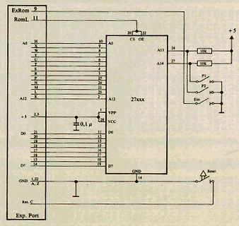
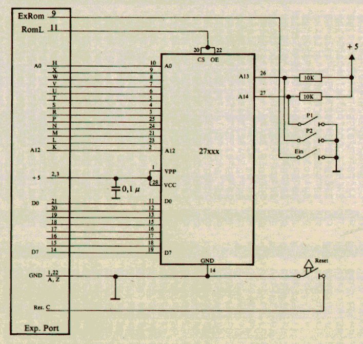
Schaltplan eines EPROM-Bausteins
ExRom 9 RomL 11 + 5 A0 H 10 X 9 W 8 V 7 T 6 S 5 R 4 P 25 N 24 M 21 L 23 K 2 A12 1 VPP 28 + 5 2,3 VCC D0 21 bis 11 D7 20 bis 14 GND 1,22 GND 14 A, Z Res. C Exp. Port CS 20 OE 22 A13 26 A14 27 10K 10K P1 P2 Ein Reset