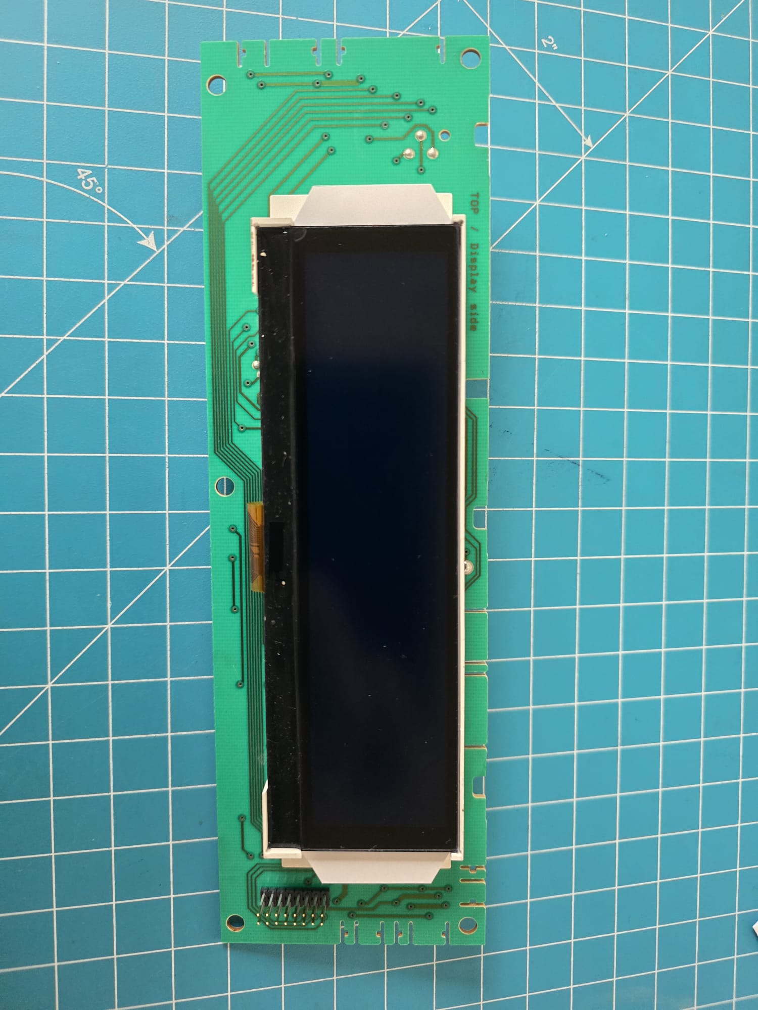
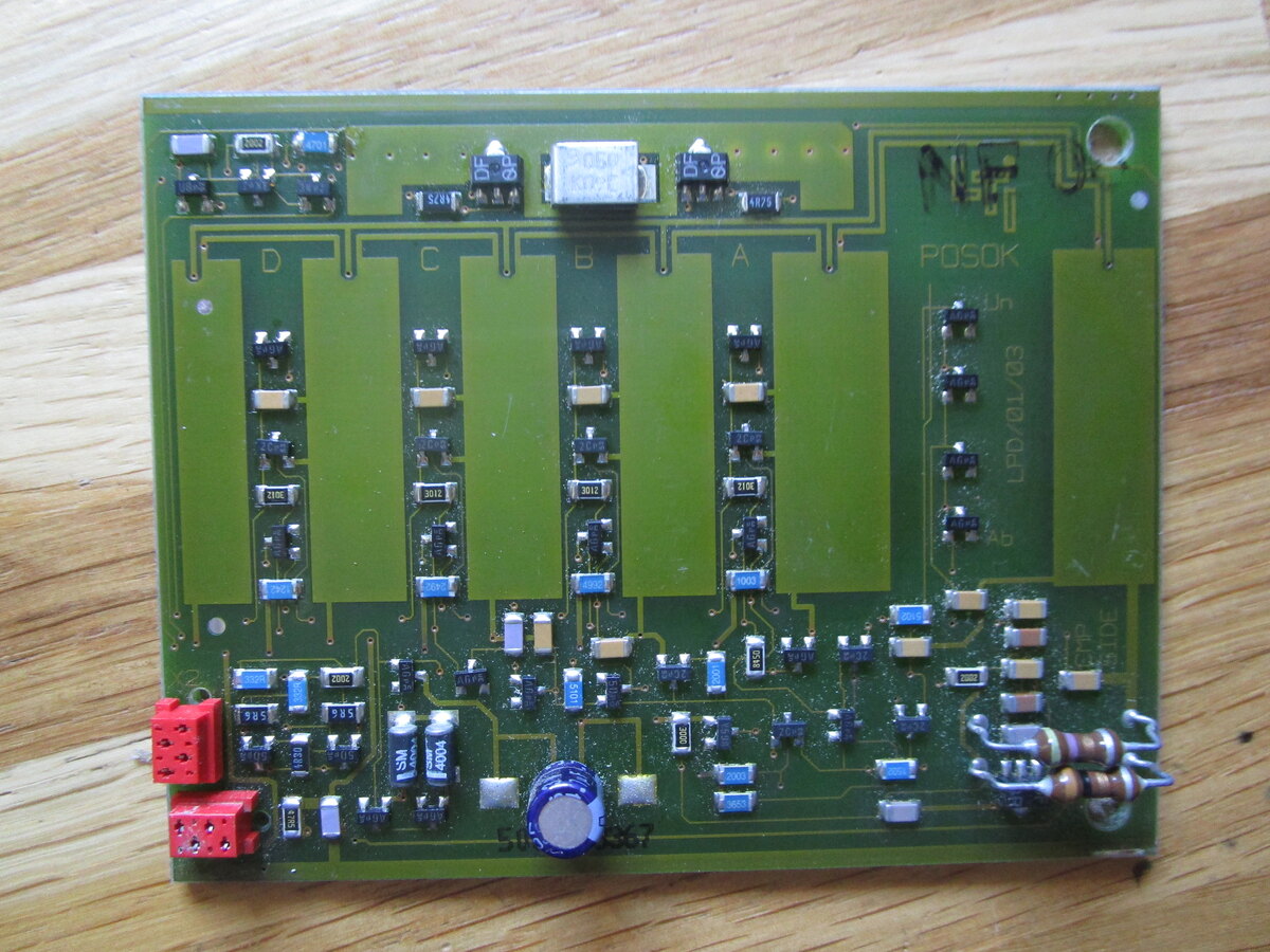
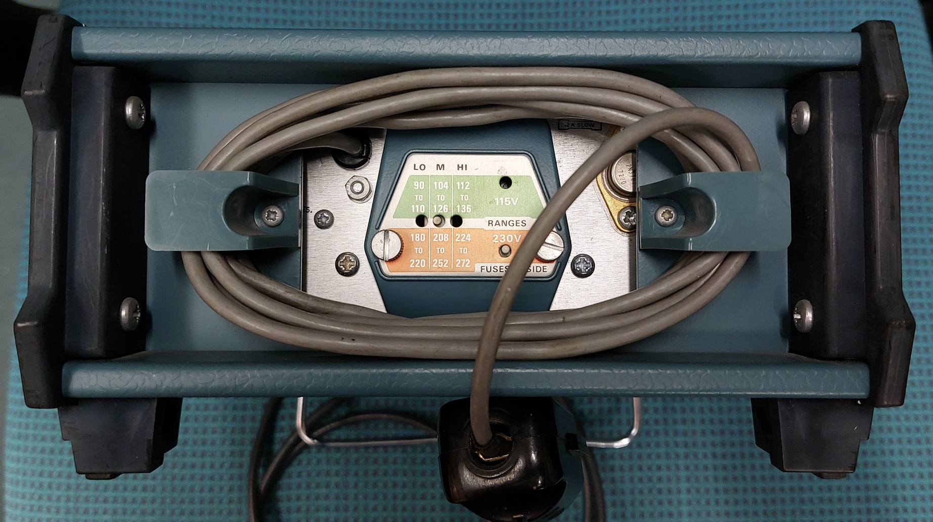
. . eee cence cece ee eee et een teense ee te nen es TAG Fig. 7.8. Display peb, lay-out component side... 0 0 s e c veee nese eteceeeee t e n s e s es TAT Fig. 7.9, Display pob, lay-out, conductor side... 6. eevee eee ee ee eee ee ee eens seen ee TAT Fig. 7.10. Preset peb,lay-out, component side... 2
siehe Bilder und hier https://newhavendisplay.com/de/128x64-graphic-cog-lcd-fstn-display-with-white-side-backlight-mounting-holes/ Alles für 8€ + 2,70€ Bücherversand (Versand DHL/Post und Paypal Bei Interesse bitte PM mit Artikelangabe. Danke! MFG Roger
Boot-Loop zu sein. Ich würde gerne herausfinden: 1. Was ist das für ein IC (Step-Down? LDO? High-Side-Switch?) 2. Ob es einen kompatiblen Ersatz gibt 3. Welche Spannungen an den Pins anliegen sollten 4. Ob jemand das Pinout oder ein internes Schema des PCM 3 kennt Messungen kann
üblich ist, Elkos raus und angucken, autsch https://www.fingers-welt.de/phpBB/viewtopic.php?p=67613&sid=496d5c6bd473e5a96e6ad5c59c004aab#p67613 2/21 17.03.26, 19:23 Reparaturerfolge - Seite 13 - Fingers elektrische Welt Da drunter sieht die Platine auch nicht mehr so ganz fabrikneu aus Wenn man so dreckig
Vout=V LX=6V 0.5 µA Fosc Oscillation Vout=set 180 kHz Frequency Vout*0.95 Maxdty Duty Ratio on(V “L”)side 84 % LX EFFI Efficiency 85 % ME2108Bxx/Dxx Fosc=180kHz SYMBOL PARAMETER CONDITIONS MIN TYP MAX UNITS V OUT Output Voltage Vout*0.975 Vout Vout*1.025 V V Oscillation IOUT=1mAÿ▯ 0.8 0.9 V start Start-up
–13 Mounting the Raised Display Unit on the Short Side of the Scale First, decide whether you want to mount the display on the short side or on the back (long side) of the scale. ! Please follow the instructions given on page1–12 before you begin to change
3DRecentlyViewedItemsV2WithMLRPboosterAndUpdatedFeatures_BP&_trksid=p4375194.c102726.m162918 und der IC: power switch high-side 2,6A N-Channel SMD SO8 INFINEON? https://www.ebay.de/itm/297561537649 Wollte mal nachfragen, bevor ich bestelle das es auch die richtigen Teile sind.
area of each pixel, the sensor achieves higher light-collection efficiency than conventional front-side illuminated (FSI) architectures. This results in quantum efficiency (QE) of up to 73% at 550 nm and 15% at 940 nm, improving performance in challenging lighting conditions and near-infrared applications
STDRIVE102-Bausteine integrieren eine fortschrittliche Ladungspumpe, die den Dauerbetrieb der High-Side-Treiberschaltung sicherstellt und so das Design von Anwendungen vereinfacht, die ein PWM-Tastverhältnis von 100 % erfordern. Integrierte 12-V- und 3,3-V-Linearpregler (LDOs) versorgen die internen Low-Side-Treiber
unit N3 5322 216 74066 (532221674066) Seite 100 (95/187) Figure 57 Display p.c.b. lay-out, conductor side: 59 pins keine der Nummern kommt in der KI-Antwort vor. Das PM2534/PM2535 verwendet das L.C.D. 5322 130 90279 (532213090279) https://manualmachine.com/philips/pm2535/4646894-service-manual/ Seite 77/114 8.1 MECHANICAL PARTS Schaltplan Seite 9-2 (89/114) Figure 9.2 Display pcb, component side ST4739 850809 hat 49 Kontaktstreifen, Ansteuerung durch D2101 PCF8576T PEL 5322 209 11129 (Seite 86/114) Das Segment-Layout und die Segment-Zuordnung sieht man auf Seite 9-3 (Seite 90/114). Theoretisch
driver IC) ST7567 THIS PRODUCT CONFORMS THE ROHS OF PTC ROHS Detail information please refer web side : http://www.powertip.com.tw/news/LatestNews.asp 1.2 Mechanical Specifications Item Standard Value Unit Outline Dimension 80.0(L) *54.0(w) (except FPC length) * 9.7(H) mm ViewingArea 70.7 (W) * 38.8
C Dimensions – Millimeters Loose Insulated Rigid Leads Insulated Flexible Leads 0.5 mm FRONT VIEW SIDE VIEW FRONT VIEW SIDE VIEW FRONT VIEW SIDE VIEW L T L T L T H H H S F LL 5 0 ± 5 5 3 1 ± ± F 8 8 S T H L F Nominal Tolerance Nominal Tolerance Nominal Tolerance Nominal Tolerance Nominal Tolerance 10.0
AIRmatic/data/settings.html#400-400), lines 400 to 575 Now I'll open Wireless.ino to see the server-side handling of the session, seeds, and encryption. Read [](file:///g%3A/src/vscode/AIRmatic/Wireless.ino#1-1), lines 1 to 400 Read [](file:///g%3A/src/vscode/AIRmatic/Wireless.ino#400-400), lines 400 to
out-of-sync detection, cross-config search, distributed builds, and a proper settings UI. On the firmware side, a fundamental rework of the main loop, scheduler, and task watchdog recovers measurable CPU and power on every platform, alongside a broad set of measured optimizations across the API, audio, and helper
loss arises. For purposes of replacement, start by undoing the memory card cover on the right-hand side of the front of the instrument, this cover is fastened by two knurled screws. Press in the ejector above the memory card which will eject it far enough out of the slot for it to be conveniently removable
235-6847 International11-800-737-3360 Canada Solid State Sensors CS Series Linear Current Sensors SIDE MOUNT WITH 9SS SENSOR, SOURCE OUTPUT Sensitivity Sensed mV&N* Mtg. Supply Supply Current Offset At 12 VDC Offset Response Catalog Dim. Volt. Current (Amps Volt. Shift Time Listing Fig. (Volts DC) (mA
Bedienelemente usw. für alte Technik sucht... https://forum.zerspanungsbude.net/viewtopic.php?f=16&t=87577&sid=dc8b859c439ddefdc43b98cf005b4d22 Grüße Bernd
Substack reports. . . . Beijing Intellectual Property Court believes it is very likely that the two sides will settle all their remaining disputes through business negotiations, reaching a deal that works for both in China and overseas markets. [/c] ### RISC/V – Kurs auf Wachstum Die RISC/V-Standardisierungsorganisation
μs 1.90 μs−2.30 μs si the magnetic circuit leads to high voltage spikes that make Drive High & Low side Low side only this topology difficult to use for line voltage above 120 V. Intrinsic Galvanic no yes Isolation Additionally, it is not practical to dim the fluorescent tubes when they are driven from
und nicht über CrossOver/Wine gefrickelt werden muss. Aktueller Stand: - macOS GUI mit Python/PySide6 - Portauswahl - Presets - Single Sweep - Continuous Sweep - Waterfall - Max Hold - Peak Tracking - CSV Export - getestetes LTDZ-Protokoll über USB-Serial Bei meinem Gerät funktioniert:
www.rflambda.com/product/amplifiers/acamplifier/REMC18G40GD ### ams OSRAM SFH 4256B & SFH 4244B – Side-LEDs für Infrarot Infrarotemitter sind oft am “Rand” der Platine am Vernünftigsten. Seitlich montierbare Leuchtdioden sparen hier Komplexität (und zusammengelötete Platinen, man denke an die DOLCH-Logikanalysatoren
Reference Voltage Precision: (Ta=25°C) 0.8V±1.5% (Ta=-40°C to +105°C) ±2.0% BD9615MUV-LB is a low side MOSFET controller with Frequency Range: 100kHz to 2500kHz high withstand voltage (60V). It is suitable for circuits Operating Temperature Range: -40°C to +105°C requiring low side FET such as boost
addDataPoint(data) { const time = new Date().toLocaleTimeString(); // Add new points to END (right side scrolling) chartData.times.push(time); chartData.esp32.push(parseFloat(data.internal) || 0); chartData.ds18.push(parseFloat(data.ds18b20) || 0); chartData.scd_t.push(parseFloat(data.scd_temp) || 0); chartData.bme_t.push(parseFloat(data.bme_t) || 0); // Limit to MAX_POINTS (remove from LEFT side) if (chartData.esp32.length > MAX_POINTS) { chartData.times.shift(); chartData.esp32.shift(); chartData.ds18.shift(); chartData.scd_t.shift(); chartData.bme_t.shift(); } drawChart(); } function update
,1 enabling high dynamic range for phased-array systems and dense RF front-ends. On the transmit side, up to sixteen 16 GSPS RF-DACs support output bandwidth up to and beyond 18 GHz, achieving fully symmetric TX/RX operation for multi-channel and multi-mission flexibility. The result: engineers gain
E3630 Series Power Supplies Agilent E3631A/32A/33A/34A E3631A 80-Watt To rackmount two instruments side-by-side Lock-link Kit (P/N 5061-9694) Triple Power Supply E3632A 120-Watt Flange Kit (P/N 5063-9214) Single Power Supply To rackmount one or two instruments in a E3633A/34A 200-Watt sliding support
of the type and direction of the transistor: The welding direction of the LED: There is an aligned side that is the same with the PCB sign. Please note that the welding time of the LED should not be kept too long in case that the LED could be damaged. The electrode of the electrolytic capacitor should be aligned with the PCB side with white line. After all the welding jobs have been done, please connect the electric power instead of connecting Atmega328 and LCD(9V battery or external 5.5-12V DC power), and measuring the voltage
und S+–F−, 4× PT POLARITY Sense tauschen oder Betrag 2× LOW auf F+–F− und S+–S−, 4× PT FORCE_SAME_SIDE Mux: Strom F+→S+, Sense F−/S− 3× OPEN, gemeinsamer Knoten Tx OPEN_Tx Ader Tx, kein Messen I ≈ 0 auf F+–F−, S+–S− bleibt PT OPEN_FORCE Stromader, 3-Leiter-Fallback prüfen I ok, alle Paare mit Sx = OPEN
you what to do. 2.1 Miscellaneous voltages LocateandidentifyaMolex8poleconnectorJ1002(attheinner side of the vertical rear chassis) where an 8 pole ribbon cable coming from the MB board is connected. See photo 2.1. 2.1 All voltages are measured with respect to ground (chassis). The following voltages
heads fifty percent of the time?” “I guess that’s because the coin weighs about the same on both sides, so there’s a fifty-fifty chance it will land on one side versus the other.” I tried to avoid sounding conde- scending. I wasn’t sure I succeeded. “You haven’t answered why. You simply listed some
target area with ) tapered lead-in ramps for 0 easy DIP insertion ( a Stackable end-to-end and r side-to-side (brickwalling) l for high board density c L Housing standoffs and slots e facilitate board cleaning s u Family of 6 through 48 O positions 0 Retention-style tails or 2 - straight solder tails
connect a power supply for the antenna unit and has a standard Ethernet port on the controller/display side. Fig. 2 A typical installation as provided by the manufacturer [5]. The optional Navico Expansion Port is a common Ethernet switch. 4 Adrian Dabrowski, Sebastian Busch and Roland Stelzer 4 Methods for
Signaldekodierung. Nur Textlogs mitlesen, mehrere Sichten gleichzeitig. Technik: Python >= 3.10, PySide6, python-can, pyserial. MIT-Lizenz. Entwickelt und getestet unter Windows. Linux sollte über pyserial/SocketCAN laufen, ist aber ungetestet. **Quellcode und Installation** Das Paket liegt auf
Smith chart axis: • The horizontal axis of the Smith chart represents a pure resistor: at the left side, z = 0 (short circuit) and at the right side z = ∞. • The upper section (red part) of the horizontal axis represents impedances with positive imaginary part (series inductor +jx or parallel capacitor
conductor integrated into the package making it Single 5V Supply Operation suitable for both high-side and low side bi-directional current Low power consumption (6.5mA typical) sensing. The high bandwidth of 1.5MHz (3dB) and low Zero-Current Reference Pin (Vref) phase delay makes it ideal for current
IN nF nF 2.2 k nF 1.2 nF VCO MUTE OFF MHA364 Dimensions in mm. Fig.9 TDA1591 test board (component side). 1996 Sep 02 12 Philips Semiconductors Product specification PLL stereo decoder and noise blanker TDA1591 PACKAGE OUTLINES DIP20: plastic dual in-line package; 20 leads (300 mil) SOT146-1 D M E n l
to set the LED threshold, all LED channels are automatically disabled. channel current. The ground side of the external resistor EN/PWM is the enable and one wire dimming input for all should be star connected to the GND of the PCB. The pin LED channels. Guaranteed levels of logic high and logic low source
Q1028 C6 Q1085 C6 Q1029 H5 Q1086 B6 7 Q1030 G5 Q1031 F5 65 A B C D E F G H I J RX-V4A/TSR-400 1 (Side A) (Side A) (Side A) AMP (2) AMP (3) AMP (4) 2 CB115 3 W112 N . R D + 1 M T DIGITAL 4 (CB23) 5 6 7 66 A B C D E F G H I J RX-V4A/TSR-400 1 AMP (2) (Side B) AMP (3) (Side B) AMP (4) (Side B) 2 3 4 5
value / 100; uint8_t tens = (value / 10) % 10; uint8_t units = value % 10; // Draw the three digits side by side LCD_DrawChar8x16(x, y, hundreds, color, bg); LCD_DrawChar8x16(x + 8, y, tens, color, bg); LCD_DrawChar8x16(x + 16, y, units, color, bg); } // ------------------------------------------------
whenlabor costsfor wiring externalpower are high. user-supplied voltage or currents. Specifications Field Side Ratings Open Circuit Voltage (Switch Open) 11 VDC min., 13 VDC typical, 15 VDC max. Short Circuit Current (Switch Closed) 6 milliamps nominal Minimum Off Resistance 20 K ohms Maximum Allowable On Resistance (Wire + Contact Resistance) 500 ohms Logic Side Ratings Logic Output Voltage for G4IDC5-SW <0.5 V max. (switch closed; LED on) @ 2 mA sinking (normally open) 2.7 V min. (switch open; LED off) @ 0.4 mA sourcing Logic Output Voltage for G4IDC5-SWNC
0.19 0.1 4.9 4.3 6.2 0.50 0.3 0.06 0 Notes 1. Plastic or metal protrusions of 0.15 mm maximum per side are not included. 2. Plastic interlead protrusions of 0.25 mm maximum per side are not included. OUTLINE REFERENCES EUROPEAN VERSION PROJECTION ISSUE DATE IEC JEDEC JEITA 99-12-27 SOT403-1 MO-153 03
±1.270 7.949±1.270 (16.520) (90.600) BASE (14.000) 2X M3 X 0.5-6H 2X (3.000) MOUNTING HOLES: BOTH SIDES 7.000 0.200 MIN 3MM FULL THD BOTH SIDES 3.505+.075-.3X90 (90.600) (4.070) BASE (14.000) (61.720) 4X M3 X 0.5-6H MIN 23.505+.075-.3X90 Seagate BarraCuda Product Manual, Rev. A 19 Figure5 MountingDimensions
new U matrix, and the matrix equation do not need to be solved again, because only the right-hand side was changed. So altogether this is a quickly done task. This is also true for every further node whose noise voltage should be calculated, because only the right-hand side of step 1 changes, i.e. LU

 Bild
Bild
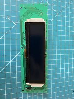
 Bild
Bild
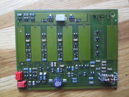
 Bild
Bild
 Bild
Bild
 Bild
Bild