°C unless otherwise noted Symbol Parameter Test Condition Min. Typ. Max. Units Off Characteristics V(BR)GSS Gate-Source Breakdwon Voltage G = 10µA, DS = 0 20 V GSS Gate Reverse Current VGS= 10V, VDS= 0 20 nA VGS(off) Gate-Source Cutoff Voltage VDS= -10V,DI = -10µA 8.0 V On Characteristics I DSS Zero-Gate Voltage Drain Current VDS= -10V, GS = 0 -0.3 -15 mA Small Signal Characteristics gfs Forward Transfer Conductance VDS= -10V, GS = 0, f = 1.0KHz 800 5000 µmhos Ciss Input Capacitance VDS= -10V, GS = 0, f = 1.0KHz 32 pF Crss Reverse
ratings for Tr1 and Tr2.> Parameter Symbol Min. Typ. Max. Unit Conditions Gate-source leakage IGSS - - 10 A VGS8V, V =0DS Drain-source breakdown voltage V 20 - - V I =1mA, V =0V (BR)DSS D GS Zero gate voltage drain current IDSS - - 1 A VDS20V, V =0GS Gate threshold voltage VGS (th) 0.3 - 1.0 V VDS10V, I =D00A - 2.5 3.5 ID=100mA, V =GS5V - 3.0 4.2 I =100mA, V =2.5V Static drain-source on-state D GS R DS (on) - 3.8 5.3 ID=50mA, V =GS8V resistance - 4.5 9.0 ID=20mA, V =GS5V - 6.0 18.0 ID=10mA, V =GS2V Forward transfer admittance
bei >40 ms liegen, würde ich den Kauf schon riskieren und es einfach austesten (z. B. Heizstab auf 10 % für 30 min, alle anderen Verbraucher aus und prüfen, um wie viel sich der Gesamtverbrauch erhöht hat). Ansonsten: Spricht irgendetwas gegen den RGC1P48V30ED, bzw. bin ich bei meinen Überlegungen
im Beitrag #7966201: > An meinem Zähler ist die Saldierungszeit knapp 1 s, der ist aber schon > 10 Jahre alt. Im Netz liest man mittlerweile auch von 500 ms. Energiezähler EasyMetec Q3MA: Saldierungszeit >100ms 0,1s PWM-Zykluszeit funktioniert tadellos, bei 0,2s gibt es erste Saldierungsabweichungen
.png) Bildquelle: Nuvoton Zu den sonstigen Leistungsdaten vermeldet man folgendes: [c] The MA35D05KH67C, MA35D05KI67C, and MA35D05KJ67C feature a dual-core 64-bit Arm® Cortex®-A35 architecture operating at up to 650 MHz and integrate a dedicated Arm® Cortex®-M4 real-time processing core operating
requirements, the new devices provide a rich set of peripheral interfaces, including Gigabit Ethernet, USB 2.0 High-Speed Host/Device, SD 3.0/eMMC, CAN FD, Quad SPI, UART, I2C, I2S, PWM, and ADC. Developers can also accelerate evaluation and deployment of industrial edge and IIoT applications using the NuMaker-IoT-MA35D0
Bereich liegen. Woher nimmst du diese Zuversicht? p.s. https://de.wikipedia.org/wiki/Vors%C3%A4tze_f%C3%BCr_Ma%C3%9Feinheiten
beachteter Rechenfehler ist weiß ich nicht. In der Spielstraße oder beim Ausparken kann man auch von 0 mit 1-2-3-4-5 lofahren, es ist also nicht wie der Autotacho "geht erst ab 10 los", aber da ist definitiv ein Bock drin. Das Teil muss filtern, aber es ist immer zu hoch. Matthias S. schrieb im Beitrag
Solderjumper vorsehen? > Wenn man einen Elko als Spannungsquelle verwenden möchte macht es evtl > Sinn 5V VCC zu ermöglichen weil dann 5V-1V1 Bereich möglich ist. Dann > bräuchte man aber für 3V3 uC einen optionalen Pegelwandler. Der RV-3032 läuft natürlich auch mit 5V, denk dir einfach das 3.3V-Symbol
Flussspannung und wie hoch darf die > Strombelastbarkeit sein? Es ist eine Silizium-Diode, also um die 0.6 Volt. Wenn mehr als ein paar mA nötig sind, wird schnell das Gehäuse zu klein für die Verlustleistung. Dann nehme ich doch lieber "echte" Dioden, so SMA aufwärts. 900ss schrieb im Beitrag #8095795
selecting this resistor is to make it higher than the apparent dynamic impedance of the Base input: V BE(on) Z B + (23) IB then:ZB= 1.10/0.18 = 6 Ω Let us select B = 15 Ω, then: V BB ≥ 15*0.18+1.10+1 V BB ≥ 4.80 V B R R b b Q1 Q1 Nb VBB Nb Cb Ri VBT R Re e VEE V EE Figure 19.(b) Typical Voltage Mode
voltage VDD(PVDD) = 3 V; O = 4 mA V DD(PVDD) - VDD(PVDD) V 0.4 V OL LOW-level output voltage VDD(PVDD) = 3 V; O = 4 mA V SS(PVSS) - VSS(PVSS)+ V 0.4 IOL LOW-level output current VDD(PVDD) = 3 V - - 4 mA IOH HIGH-level output current VDD(PVDD) = 3 V - - 4 mA Pins AUX1 and AUX2 V OH HIGH-level output voltage VDDD = 3 V; O = 4 mA V DDD 0.4 - VDDD V V OL LOW-level output voltage VDDD = 3 V; O = 4 mA V SS(PVSS) - VSS(PVSS)+ V 0.4 IOL LOW-level output
Sensor laut Datenblatt das nicht hergibt, oder? Ich habe aber dank diesem Video: https://youtu.be/1jV7Qzr3OQ0?si=R-4wQruQkPgwnFbO&t=1053 auch mal in meine Kamera reingeschaut und auf der Sensorplatine steht bei mir "YW5609_IMX307_V2", was mich vermuten lässt, dass ich den (besseren? [relativ zum IMX323
wird. 4) 96.1% positive reviews 15.3K followers Store name: Eakins Store Store ID: 836673 Open since: Sep 20,2013 https://industrial-microscope.aliexpress.com/store/836673?spm=a2g0o.detail.0.0.4266DY1VDY1VmD
4) V(+) or V(−) Gnd–0.05 VCC+0.05 VDC 1 DC Common-Mode Error Over Analog Input Voltage ±1/16 ± 8 LSB Range Power Supply Sensitivity VCC =5 VDC ± 10% Over ±1/16 ± 18 LSB Allowed VIN+) and VIN−) Voltage
Der Batteriehalter heißt BCR20H4. Anleitung im Datenblatt.
Wolfgang R. schrieb im Beitrag #8003616: > Der Batteriehalter heißt BCR20H4. > Anleitung im Datenblatt. https://www.mikrocontroller.net/attachment/689342/bcr20h4.pdf Das ist m.A.n. schon ein sehr hochwertiger Batteriehalter, anders als das eas man sonst so kennt.
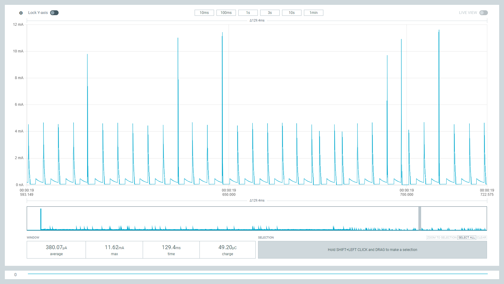
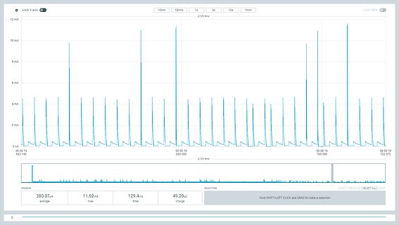
Lock Y-axis 10ms 100ms 1s 3s 10s 1min LIVE VIEW 12 mA 10 mA 8 mA 6 mA 4 mA 2 mA 0 mA 00:00:19 593.149 00:00:19 650.000 Δ129.4ms 00:00:19 700.000 00:00:19 722.575 WINDOW SELECTION ZOOM TO SELECTION SELECT ALL CLEAR 380.07µA average 11.62mA max 129.4ms time 49.20µC charge 0
Besteht das "kleine Projekt" aus einer Gross-Serie? Willst du die Beschaffbarkeit des CPLDs für 10-20 Jahre sichern? Für kleine Stückzahlen bekommt man immer noch jede Menge abgekündigter/eingesteller CPLD Chips, sogar noch GALs wenn es unbedingt sein muss.
langsamsten speedgrad mit Größenklasse -400 und -1000 recherchiert. Da war nie was mit Preisen unter 10€ eher so um die 15-20 €. (Industriepreis ohne MwSt.)
Hab sowohl DL24, EBC-A20 (für mehre Zellen bis 30V, 20A, ABER: auch Grenze 85W! und 30V, 20A nur Entladen. Laden geht nur bis 20V/5A), als auch EBC-A40L (für eine Zelle bis 5V, 40A). EBC-A20 und EBC-A40 können über das
3 A kann man den Korrekturwert auf 1 mV und 1 mA genau eingeben.
: VIN =10V to 25V SA78R12 : VIN =13V to 29V SA78R15 : VIN =16V to 30V Load Regulation RLOAD 5mA < Io < 1A 0.1 2.0 % Dropout Voltage V DROP OUT =1A 0.15 0.5 V Quiescent Current IQ O =0A;VDIS=0.4V 3 10 mA Ripple Rejection PSRR 45 55 dB Disable Voltage High VDISH Output active 2.0 V Disable Voltage Low VDISL Output disabled 0.8 V Disable Bias Current High IDISH VDIS=2.7V 20 μA Disable Bias Current Low IDISL VDIS=0.4V -0.4 mA Reference Voltage Vref SA78R00 1.24 1.27 1.30 V HANGZHOU
400 mV I HIGH current V = 10 V − − 1 A 18 18 Muting (pin 8) MUTE att mute attenuation (pin 8) V 8 0.4 V − 80 − dB V 8> 4 V − − 0.2 dB VO(offset) DC offset voltage (pins 10 and 11) after muting − − ±400 mV HCC
aber ca. 70 Jahre alt. Die beiden linken Kondensatoren 400µF und 100µF werden zur Zeitsteuerung (0,1 bis 1,5 Sek.) geladen und über Widerstand wieder entladen. Der 4µF ist zur Glättung der Gleichspannung (ca. 30V). Der rechte Kondensator 0,2µF ist zur Funkenlöschung. Danke für Inputs Axel
formiere ich die "Röhrenradio-Ersatzelkos" ab und zu in gewissen Zeitabständen. Dazu eine 1N4007 und ein 10 kOhm Widerstand in Reihe an 230V~ (Disclaimer Nicht nachmachen!). Ab und zu Spannung messen. Dann sanft entladen und Vorgang wiederholen, bis Leckstrom einigermaßen. Die neueren Elkos (für SNTs) brauchen
9 RS Data/Instruction select Value Unit 10 Data read/write Input Voltage Vdd Vdd = +5V 5.0 V R/W 11 E Enable signal Supply Current Idd Vdd = +5V 5.0 mA 12 /CS Chip select LCD Driving o Vdd-Vo 25 C 17.6 V 13 /RST Reset signal Voltage 14 Vo Contrast
9 RS Data/Instruction select Value Unit 10 Data read/write Input Voltage Vdd Vdd = +5V 5.0 V R/W 11 E Enable signal Supply Current Idd Vdd = +5V 5.0 mA 12 /CS Chip select LCD Driving o Vdd-Vo 25 C 17.6 V 13 /RST Reset signal Voltage 14 Vo Contrast
Unit Storage Temperature Tstg −40 to 85 °C Operating Temperature T −40 to 85 °C opr Supply Voltage V CC −0.5 to 7 V Low Level Output Current OL 20 mA High Level Output Current OH −1 mA Soldering Temperature Tsol 260 (Note 1) °C Note 1: Soldering time ≤ 10 s (More than 1 mm apart from the package). 2
Die Bluetooth Reichweite beträgt in der Wohnung ca. 10 Meter, kann aber bei moderneren Standards (Bluetooth 5.0+) im Freien bis zu 300 Meter erreichen.
Jack V. schrieb im Beitrag #8034665: > Du beschaffst dir illegal Zugangsdaten im Darknet Falsch. Sowas gibts ganz öffentlich zugänglich, gratis. Jack V. schrieb im Beitrag #8034665: > Für das Projekt
drawing 1.3 Absolute Maximum Ratings Item Symbol Condition Min. Max. Unit Power Supply Voltage VDD - -0.3 3.6 V LCD Driver Supply Voltage V0-XV0 - -0.3 16 V Operating Temperature TOP - -20 70 ℃ Storage Temperature T - -30 +80 ℃ ST Storage Humidity H Ta<60 ℃ - 90 %RH D PE12864LRF-042-H-Q (DK) Page4 SAMPLE
free-air temperature PARAMETER TEST CONDITIONS MIN TVP MAX UNIT Iv Luminous Intensity (See Note 2) V ee= 5 v. IF= 10 mA 40 110 µcd hp Wavelength at Peak Emission 640 655 670 nm ~;\ V ee= 5 v, V L E o= 4V Spectral Bandwidth 20 nm V1H High-Level Input Voltage 2 v V1L Low-Level Input Voltage 0.8 v V1K Input Clamp Voltage V ee= 4.5 v, 11 = -1 2 mA -1 .5 v l1H High-Level Input Current V ee= 5.5 v, V1=2.4 V 150 µA l1L Low-Level Input Current V ee= 5.5 v, V1=0.4 V -1 mA Irow Row Input Current l Row 1 thru Row 6 500 800 J Row7
the Absolute Maximum Rating System (IEC 60134). SYMBOL PARAMETER MIN. MAX. UNIT VDD supply voltage −0.5 +7.0 V VI input voltage VSS − 0.5 V DD+ 0.5 V I DC input current − ±20 mA I O DC output current − ±25 mA DD supply current − ±100 mA SS supply current − ±100 mA Ptot total power dissipation − 400 mW
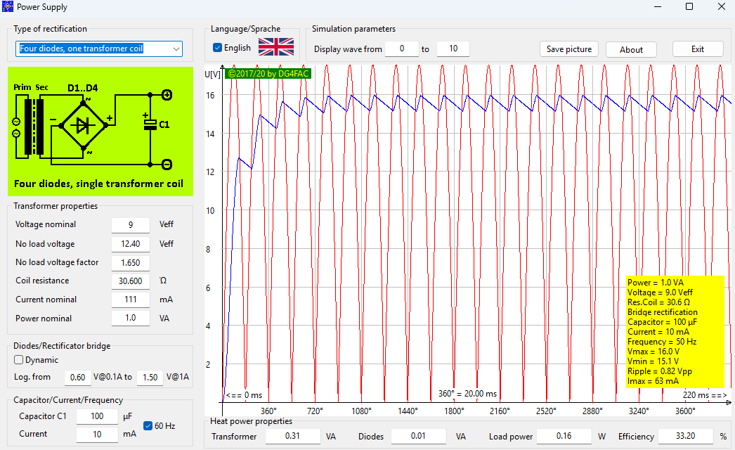
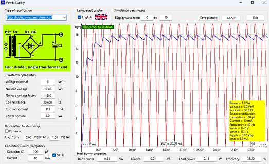
1.0 VA
Language/Sprache
English
Display wave from 0 to 10
Save picture
About
Exit
U[V]
16
14
12
10
8
6
4
2
<== 0 ms
360°
720°
1080°
1440°
1800°
2160°
2520°
2880°
3240°
3600°
360° = 20.00 ms
Heat power properties
Transformer 0.31 VA
Diodes 0.01 VA
Load power 0.16 W
Efficiency 33.20 %
Power = 1.0 VA
Voltage = 9.0 Veff
Res.Coil = 30.6 Ω
Bridge rectification
Capacitor = 100 µF
Current = 10 mA
Frequency = 50 Hz
Vmax = 16.0 V
Vmin
p 4.0 L u U O 3.0 G 3.1 R 2.0 V 1.0 detect 3.0 0.0 -40 -20 0 20 40 60 80 100 120 0 10 20 30 40 50 60 Temperature [˚C] Power Supply Voltage : VCC [V] Figure 18. UVLO Threshold vs Temperature Figure 19. VREG
to clock period) tHIGH 35 - 65 Outputs (note 4) DABD,CLBD,WSBD Output voltage LOW at IOL= 0,8 mA VOL a - 0,4 V Output voltage HIGH at -IO H= 0,2 mA VOH 2,4 - VDO V pF Load capacitance CL - - 50 XSYS (note 8) - 0,4 V Output voltage LOW VOL a Output voltage HIGH VOH 2,4 - VDD V Load capacitance CL - - 50 pF DOBM Voltage across a 75Q load via attenuator; see Fig. 10 (peak-to-peak value) 0,4 - 0,6 V VL(p-p) D.C. offset voltage VLDC -0,05 - + 0,05 V TIMING Operating frequency
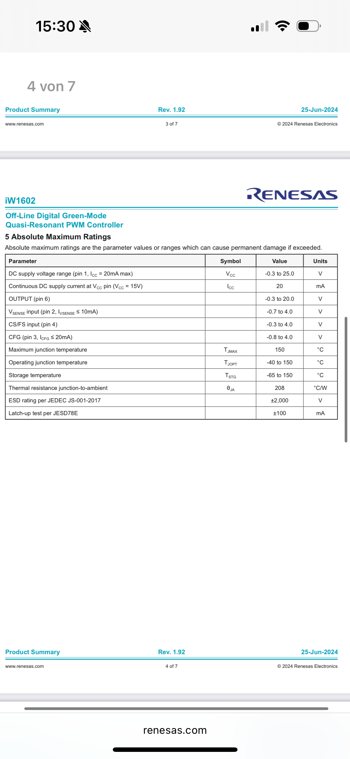
Symbol Value Units
DC supply voltage range (pin 1, ICC = 20mA max) VCC -0.3 to 25.0 V
Continuous DC supply current at VCC (VCC = 15V) ICC 20 mA
OUTPUT (pin 6) -0.3 to 20.0 V
CS/FS input (pin 4) VSENSE input (pin 2, IISENSE <= 10mA) -0.7 to 4.0 V -0.3 to 4.0 V
CFG (pin 3, ICFG <= 20mA) -0.8 to 4.0 V
Maximum junction temperature TJMAX 150 °C
Operating junction temperature TJOPT 150 °C
Storage temperature TSTG -65 to 150 °C
Thermal resistance junction-to-ambient θJA 208 °C/W
ESD rating
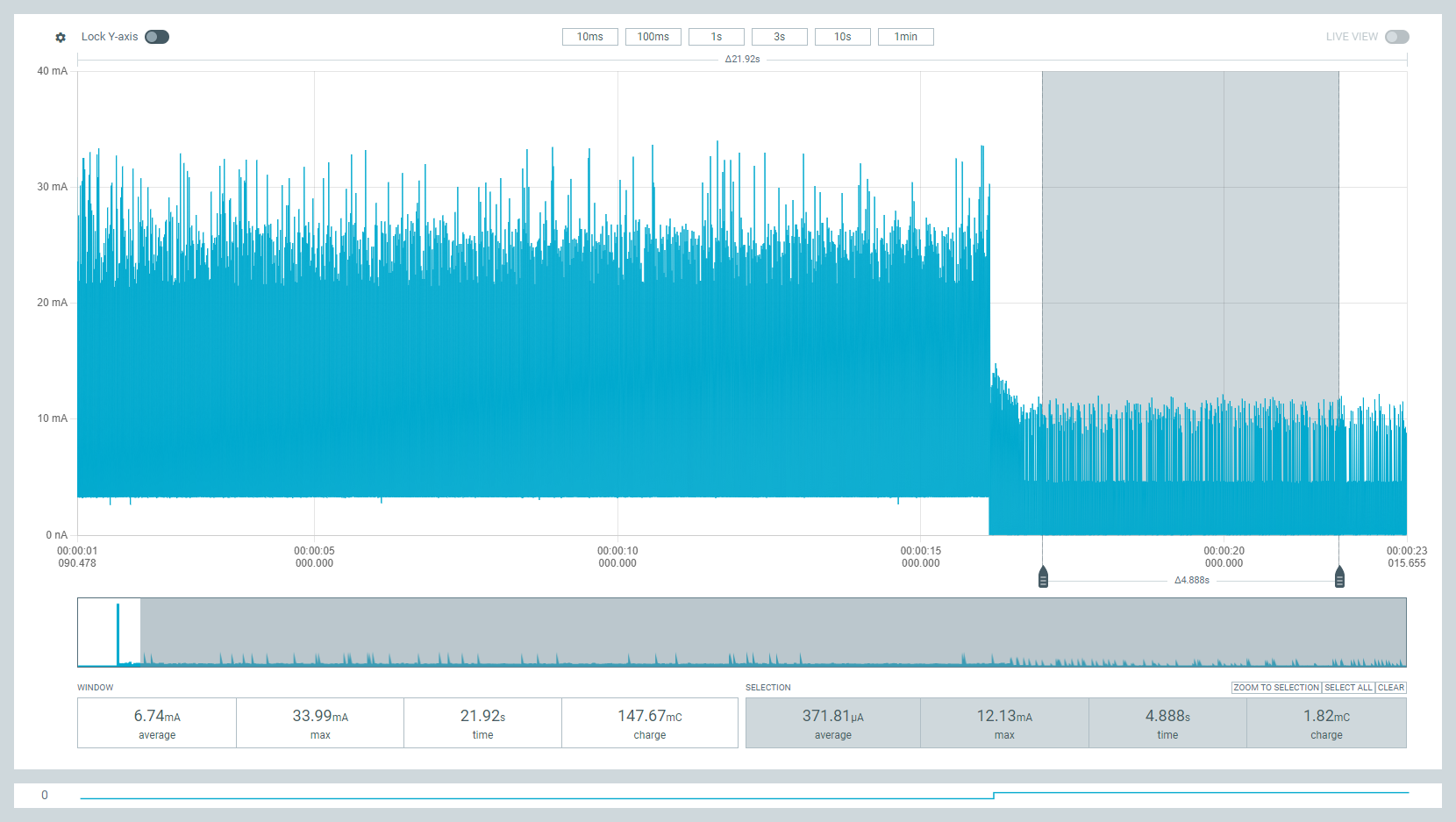
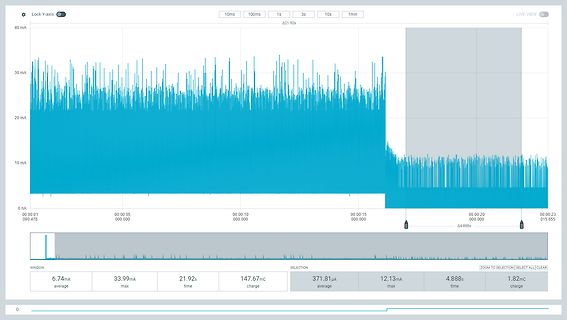
Lock Y-axis 10ms 100ms 1s 3s 10s 1min LIVE VIEW 40 mA 30 mA 20 mA 10 mA 0 nA 00:00:01 00:00:05 00:00:10 00:00:15 00:00:20 00:00:23 090.478 000.000 000.000 000.000 015.655 WINDOW SELECTION ZOOM TO SELECTION SELECT ALL CLEAR 6.74mA average 33.99mA max 21.92s time 147.67mC charge 371.81µA average 12.13mA max 4.888s time 1.82mC charge
VIN IIN40mA 0.8 1.5 V 输入电流范围 IIN V IN.2V 3 150 mA 关断状态电流 SD V IN.2V,V SOL=0.4V 30 μA 功率开关 开关导通电阻 RDS(ON) VIN1.2V, 0.65 Ω 输出漏电流 LEAKAGE VSOL=VIN 19 μA 太阳能控制 V -关 0.37 V 使能输入阈值 V IN.2V V -开 0.3 V 充电最小压差 VCH VIN1.2V,
Signal line 256 Gray level 3 channal Constant current LED drive IC Electrical CharacteristicsAT =-20~+70℃,V =DD5~5.5V,V =0VSSnless otherwise specified) Prameter Smybol conditions Min Tpy Max Unit Low voltage IOL ROUT —— 18.5 —— mA output current Idout Vo=0.4V,D OUT 10 —— —— mA Input current II VI=VDDV SS —— —— ±1 µA V IH D INET 0.7VDD —— —— V Input voltage level —— V IL D INET —— 0.3 VDD V Hysteresis voltage V D ,SET —— 0.35 —— V H IN Switching characteristics(A =-20~+70℃,V =4DD~5.5V,V =0V,SSless otherwise specified
der OP auch bis V+ aussteuern kann, er kommt am Ausgang bis (fast) auf V- runter. Nur die Eingange vertagen dann 0V bis ... Bekanntestes Beispiel z.B. der LM 358. Dafür gibt es Rail to Rail OPs, aber auch hier gilt,
. Im Datenblatt steht, dass die Eingangsspannung bis max. 20V. Ich dachte den Baustein kann ich dann auch mit 12V versorgen.
Sender mit IRMPsnd und nutzt eine RF Fernbedienung für IRMP. Frank (ukw) hatte das drahtlos Protokoll x10 eingebaut. Passende x10 Fernbedienungen gab es mal günstig Best.Nr. 721 812 https://www.pollin.de/p/pc-funkfernbedienung-x10-721815 ich bin leider noch nicht zum Nachbau gekommen. https://www.mikrocontroller.net

 Bild
Bild
 Bild
Bild
 Bild
Bild
 Bild
Bild
 Bild
Bild
 Bild
Bild
 Bild
Bild