dans ce mode d’emploi appartiennent à leurs propriétaires respectifs. ▯ En tant que partenaire du programmeNERGY STAR®, iiyama a déterminé que ce produit répondait aux directives pour l’économie d’énergie édictées pNERGY STAR . POUR VOTRE
not subject the soldering tip to physical force. G Note The control units have been adapted to hold a medium-sized soldering tip. Discrepancies may occur if the tip is changed Tr a different shaped tip is used. C 7 Special functions The special functions are divided into 2 menu levels: P 2 s ➾ Menu 1
is the same as the signal launched For falling edge signals, a clamp diode to ground effects a at the source end except of course for the propagation delay and losses and dispersion in the line. This and the analyses similar ideal termination. Note that for diode
xxxxxxxxxxxxxxxxxxxxxxxxxxxxxx xxxxx xxxxxxxxxxxxxxxxxxxxxxxxxxxxxxxxxxxxxxxxxxxxxxxxxx xxxxxxxx C P M xxxxxxxxxxxxxxxxxxxxxxxxx xxxxxxxxxxxxxxxxxxxx xxx N O r R M d 5 X P u 2 P N t S Y a ADDRESS DATA e P a m U s RX L e SA A0 A1 A2 A3 A4 A5 (1)R/W SO SA D0 D1 D2 D3 D4 D5 D6 D7 SO c C e o t n d u c o r ADDRESS s TX SA A0 A1 A2 A3 A4 A5 (1) R/W SO l f m o R p e v . d MX . n — s 1 o DTRQ 1 7 m 001aak589 9 A n S p s a l b (1) Reserved. n 2 c d 1 o Fig 10. UART write data timing diagram a 6 g d d p l Remark: The data byte
la lampe ou controller le compteur d’heures régulièrement (quand disponible) et remplacer la lampe à temps. La lampe usée est à conserver dans un récipiant de protection et à manipuler avec précaution. La lampe utilisée a une température moyenne de 600° C. Avant le remplacement de l'ampoule, toujours
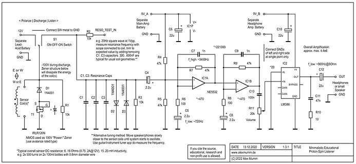
frequency with scope connected to value, trim to expected value by adding/removing C1,C3 capacitors. 300...600nF are typical for usual coil geometries.** 9V_A Separate Main-Amp Battery C6 22u IC1P V+ GND 9V_B Separate Headphone Amp. Battery C10 22u V- GND Overall Amplification: approx. max 4.4e6 IC2 f_low:~900Hz
einer Periode im Intervall [0,T] wie folgt definiert: Der Wert des Tastverhältnis p kann dabei Werte zwischen 0 und 100% annehmen. Der zeitliche Mittelwert der Spannung innerhalb eines Intervalls [0,T] ist unten stehend beschrieben. ist dabei normalerweise 0V, die Betriebsspannung ,
Die Transistoren des linearen Verstärkers sind nur halb durchgesteuert. Es fließt ein Strom von ca. 600 mA, in der Heizung werden ca. 3,6 W in Wärme umgesetzt. Allerdings werden auch 4,2 W im Verstärker in Wärme umgesetzt! Der Wirkungsgrad ist nur noch 46%! Im Gegensatz dazu sind bei einer PWM die Transistoren
C D B C D NUMBER (K)85 NAME (%) A (K) (K2) (K ) A1 (K ) (K )2 (K ) 1 2880 Mat O. with 3 - 9.094 2251.74 229098 - 2.744820E+07 3.354016E-03 3.495020E-04 2.095959E-06 4.260615E-07 Bn = 2880K 2 2990 Mat P. with 3 -10.2296 2887.62 132336
C D B C D NUMBER (K)85 NAME (%) A (K) (K2) (K ) A1 (K ) (K )2 (K ) 1 2880 Mat O. with 3 - 9.094 2251.74 229098 - 2.744820E+07 3.354016E-03 3.495020E-04 2.095959E-06 4.260615E-07 Bn = 2880K 2 2990 Mat P. with 3 -10.2296 2887.62 132336
M M P P I I T E E M D P C A E A A A M I E S M E T U U E E B B R U U E O E E I A I I I B T F B N A T T - - L L E R R N N A S U S S S D L CAUSE POSSIBLE R O L S E A A C C E E T D U R D E E O R E A U E T I I
M M P P I I T E E M D P C A E A A A M I E S M E T U U E E B B R U U E O E E I A I I I B T F B N A T T - - L L E R R N N A S U S S S D L CAUSE POSSIBLE R O L S E A A C C E E T D U R D E E O R E A U E T I I
the orbits. This means not only that larger objects have longer orbits, but also that the speed of a planet in a longer orbit is lower than in a smaller orbit: P 2 3 is constant for all planets. a P = orbital Period, a = semi-major axis of the orbital ellipse From this law the satellite orbital altitude
commercial environments Safety related data safe state Load circuit open function test interval maximum 1 a diagnostics test interval by internal test function maximum 600 s stop category according to IEC 60204-1 0 B10d value 2 500 000 failure rate [FIT] at rate of recognizable hazardous failures 1 400 FIT
1 48-pinTQFP pin definitions Pinname Pin Type [1] Description number Power and clock VCC_A 1 P 3.3 V analog power to thechip VCC_A 7 P 3.3 V analog power to thechip VCC_A 12 P 3.3 V analog power to thechip VCC_A 16 P 3.3 V analog power to thechip VCC_A 19 P 3.3 V analog power to thechip VCC_D
220V—Alarm - f Signale Ausgang Bild 4: Blockschaltbild einer BK-Verstärkerstelle m) m | | FspW | | A/B-Zw Vr(P) ^ A' 'A ü¥m¥^iH* ZI tift v — Llsv^Y “ Tb/ ------- XIS JL(2) p / Mf a / ___ dl 8 14/9 3/7 l<— — O l £ Ol - A n BF®f2 ■ KfrOTe RüK M ? 2$ CVr ER E s-m i - & ' CI " c 4 \ 01 b 2 fe: i l^iiT kl
R H 5 6 0 0 2 61 0 2 0 1 2 C 6 K 0 1 2 C 0 2 A T + 1 C C Q 1 R 5 K 0 2 K 2 P 9 P 5 P 6 P 0 K 4 D 6 5 4 3 2 1 : 5 0 1 8 9 0 2 R H I 4 N 5 7 0 9 0 R 0 R _ E T O 1 B K 1 K 9 P A 2 N 4 C 4 C E D U 6 U 7 R R P 1 F 9 F 0 03 0 2R 6 T P 0 R K7 K 5 P E B
a a m > > )- 0 2u I -' u cC c . c· u CQ I : - ; C E _ l n s. .' : N >: c2 n R P B electronic-taschenbücher Die Konzentration des Wissens nicht zu erklären. Wer hätte dazu und der Erfahrung auf das noch
stehen system mit Blockierverhinderung durch Bremskraft- Netz allerAutomarken in Deutschland, über 1.600 regier. Kundendienst-Stellen! R E N A U L T Renaultempfiehltelf Motorenöle. Fachzeitschrift für die gesamte P U B L IK A T IO N FUNK Unterhaltungselektronik rECHNIK ISSN 0016-2825 Gegründet von Curt
column of the CCD as function of the angular position a of the grating. (c) Horizontal pixel number p onto which a fixed wave- lengths impinges, as a function of different angular positions of the grating. 149 Am. J. Phys., Vol. 92, No. 2, February 2024 Eggenberger
T52 T53 R53 22k 10k 22k 27k T42 T49 T57 R28 R29 R33 R34 F R46 500 T55 R56 T56 F T40 1.0k T41 1.0k A R48 R64 P / R39 R47 500 R57 500 F 500 1.0k l 1.0k A T39 R40 R41 t R50 R61 R62 R65 P 2.0k 2.0K u 220 2.0k 2.0k 220 Y B R – T43 T44 B l t T60 T61 B–YClamp r 11 B T62 T63 T64 T65 T45 T46 R60 R47 4.7k 4.7k
T.) Symbol Name Conditions Min Typ Max Units TPS Turn−On time, EN/PWM rising tLED from ILED= 175 mA 1.5 ms shutdown ILED= 80 mA 1.3 TP1 Turn−On time, EN/PWM rising tLED ILED= 175 mA 600 ns TP2 Turn−Off time, EN/PWM fallingLED I ILED= 175 mA 400 ns I = 80 mA 300 LED T LED rise time I = 175 mA 700 ns
for special WRITE timing or limitations on the number of WRITEs that can be performed. The 28-pin, 600 mil DIP CAPHAT ™ houses the M48T58/Y silicon with a quartz crystal and a long life lithium button cell in a single package. The 28-pin, 330 mil SOIC provides sockets with gold plated contacts at both
auch die Artikel in der Kategorie AVR-Boards und den Artikel zur AVR Programmierung. STK200 STK500 STK600 AVR-ISP / AVRISP mkII AVR Dragon AVR Butterfly AVR Raven AVR JTAG-ICE AVR-ISP-Stick RN-Control C-Control PRO (AVR32) myAVR Board Pollin-Starterkit aTeVaL-Board – Nachfolger des bekannten Pollin Evalboards
ATxmega-Serie verfügen über mehr Funktionen als die "traditionellen" AVR (z.B. DMA- und Eventsystem, 12Bit A-D-Wandler). ATxmega sind jedoch für 3,3V-Betrieb ausgelegt und ausschließlich in SMD-Bauform erhältlich. __NOTOC__
MATERIALS INFORMATION www.ti.com 26-Sep-2025 TAPE AND REEL INFORMATION REEL DIMENSIONS TAPE DIMENSIONS K0 P1 W B0 Reel Diameter Cavity A0 A0 Dimension designed to accommodate the component width B0 Dimension designed to accommodate the component length K0 Dimension designed to accommodate the component thickness
Sense Logic a) (P10, P11, P14, P15, P16, P21 and P22 only) VDD VDD VBAT VFLD Port Logic Level Shifter Port I/O Driver P26ON PIN OUTPUT OUT PULL DATA WR Q DATA RD VSS VSS VSS b) Figure 25. Port 1 and Port 2 Configuration
Verlag 3. Aufl. 2001 384 S. Wunsch, Schulz Elektromagnetische Felder VEB Verlag Technik 1989 336 S. F. P. Zantis Energy Harvesting Stromversorgung ohne Stress Elektor Verlag 2021 188 S. A. Zischka Pioniere der Elektrizität Bertelsmann Lesering 3. Aufl. 1958 317 S. Topp Buchreihe Elektronik Verlag Frech
drain current TC= 25 °C I 602 TC= 125 °C D 347 Continuous source current (diode conduction) IS 545 A a Pulsed drain current IDM 655 Single pulse avalanche current AS 76 L = 0.1 mH Single pulse avalanche energy EAS 288 mJ T = 25 °C 600 Maximum power dissipation C PD W TC= 125 °C 200 Operating junction
40 (1985),Heft12 M M M M M M F Ü r Aus- und Weiterbildung M M M M I 9+14 u Analoggröße 1 B il7 .1 .P r i n z iD e t a i l s ce i nA n a l o g s c a l s t e r s P A M B il7 .1 P u l s a b tz w e iA n a l o g glm M u lt ip l e x v e r f a h - r e n ► Das Bild7.1.2zeigtdie innerePrinzipschaltungeines Pulsampli
A D November 1999 C 0 8 1 A ADC0801/ADC0802/ADC0803/ADC0804/ADC0805 D C 8-Bit µP Compatible A/D Converters 0 8 General Description n Differential analog voltage inputs 0 The ADC0801, ADC0802, ADC0803,
auf 9600 Baud eingestelllt werden. Beispiel der avrdude-Kommandozeile: avrdude -c avr910 -b 9600 -P -p -U mySmartUSB. Der mySmartUSB Programmer von myAVR ist ein kompakter ISP Programmer mit USB Anschluss (der Preis liegt bei 28€). Lt. Hersteller kann er auch für die Kommunikation via UART, TWI, SPI
on the Atmel AVR Butterfly development board. ButtLoad is specially written firmware which converts a low-cost official Atmel Butterfly evaluation board into a smart ISP programmer for other members of the Atmel AVR family. It supports the entire AVR range, and allows for a complete program (including
0x9A TB8 bit 0x9B REN bit 0x9C SM2 bit 0x9D SM1 bit 0x9E SM0 bit 0x9F P20 bit 0xA0 P21 bit 0xA1 P22 bit 0xA2 P23 bit 0xA3 P24 bit 0xA4 P25 bit 0xA5 P26 bit 0xA6 P27 bit 0xA7 EX0 bit 0xA8 ET0 bit 0xA9 EX1
Y A A Y R A A A A A A A A Y R A A Y WV U T R P N M L A A Y WV U T R P N M L A A Y WV U T R P N M L A Y A Y WV U T R P N M L WV U T R P N M L U1E NQ82915PM 6 6 6 6 6 6 6 6 6 6 5 5 5 5 5 5 5 5 5 5 4 4 4 4
base, RG-174 type, 1.5 m A-CRF-RMNM-L1-300 N-type (male) to RP SMA (male) LMR-195 Lite cable, 3 m A-CRF-RMNM-L1-600 N-type (male) to RP SMA (male) LMR-195 Lite cable, 6 m A-CRF-RMNM-L1-900 N-type (male) to RP SMA (male) LMR-195 Lite cable, 9 m Surge Arrestors A-SA-NFNF-02 0 to 6 GHz, N-type (female) to N-type (female) surge arrester A-SA-NMNF-02 0 to 6 GHz, N-type (male) to N-type (female) surge arrester Wireless Adapters A-ADP-RJ458P-DB9F-ABC01 DB9 female
base, RG-174 type, 1.5 m A-CRF-RMNM-L1-300 N-type (male) to RP SMA (male) LMR-195 Lite cable, 3 m A-CRF-RMNM-L1-600 N-type (male) to RP SMA (male) LMR-195 Lite cable, 6 m A-CRF-RMNM-L1-900 N-type (male) to RP SMA (male) LMR-195 Lite cable, 9 m Surge Arrestors A-SA-NFNF-02 0 to 6 GHz, N-type (female) to N-type (female) surge arrester A-SA-NMNF-02 0 to 6 GHz, N-type (male) to N-type (female) surge arrester Wireless Adapters A-ADP-RJ458P-DB9F-ABC01 DB9 female
From A Register SLAVE REGISTER SLAVE LO BYTE HI BYTE S ADDR + W A ADDR A P S ADDR + R A DATA A DATA N P S START A ACKNOWLEDGE DRIVEN BY THE MASTER P STOP N NO ACKNOWLEDGE DRIVEN BY ISL88731 FIGURE 18. SMBus

 Bild
 Bild
 Bild
 Bild