NOTICE. THE PRODUCTS DESCRIBED HEREIN AND THIS DOCUMENT ARE SUBJECT TO SPECIFIC DISCLAIMERS, SET FORTH AT www.vishay.com/doc?91000 150 RMI www.vishay.com Vishay BCcomponents ADDITIONAL ELECTRICAL DATA PARAMETER CONDITIONS VALUE Voltage Surge voltage U s 1.15 x U R Reverse voltage Urev≤ 1 V Current Leakage
pro Etage. ich kann > sagen, 18 Stück gehen noch an einem ESP32 Portpin :) Oha. So viele DS18B20s an einem ESP32. Wusste nicht, dass das geht. Die DS18B20s haben halt "nur" eine Genauigkeit von +-0,5K bei Original-Maxim. Wenn es asiatische Abklatsche sind, dann wahrscheinlich eher darüber. Dann
Timo N. schrieb im Beitrag #7990856: > Oha. So viele DS18B20s an einem ESP32. Wusste nicht, dass das geht. > Die DS18B20s haben halt "nur" eine Genauigkeit von +-0,5K bei > Original-Maxim. Wenn es asiatische Abklatsche sind, dann wahrscheinlich > eher darüber
/07/29/arduino-core-on-zephyr-0-90-0-is-officially-stable-and-leaving-beta/ nach folgendem Schema die Stabilisierung des Cores: [c] We are thrilled to announce the release of version 0.90.0 of the ArduinoCore-zephyr. This is a major
und Co beendeten diesen Trend. Auf AliExpress sind nun Displays mit Auflösungen von 800x800 bzw 1200x1200 Pixel aufgetaucht. 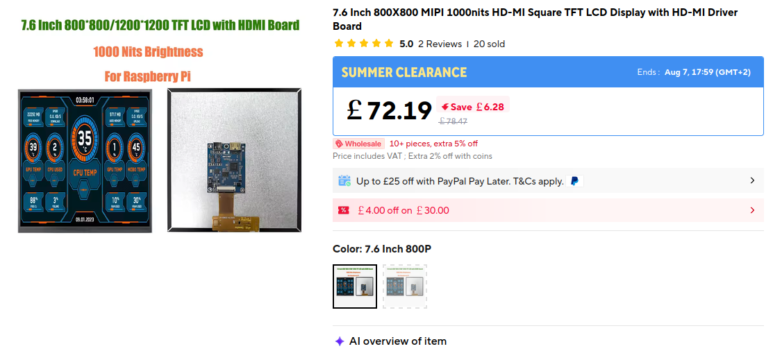 Bildquelle: https://s.click.aliexpress.com/e/_c3rXpOzd 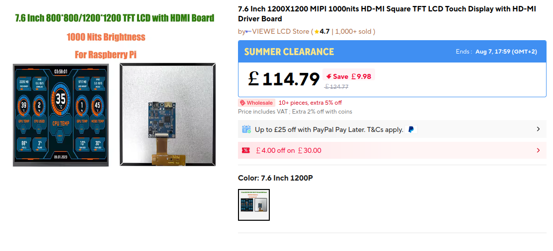 Bildquelle: https://s.click.aliexpress.com/e/_
sorgung anges hlssen ha ben,nimm dtr S L-1200 den B etreb auf. Währen d des Res e juste ren sich die Motoren aus und das Ger ä ist nac h ca. 20 Sekunden betriebsbere t. Stele n Se den Fo kus durch Vor- und Zurückbewe gen der Objektivlnse
MONITOR FEATURES ® K Crisp, Clear Display for Windows or Macintosh K Supports Resolutions up to 1600×1200 K Supports Refresh Rate up to 85Hz at 1280×1024 ® H K Windows 95/98/Me/2000 Plug & Play Compliant I K Power Management (E NERGY STAR® and VESADPMS Compliant) G N K Space Saving, Compact Case Design
0.6 Vpp will be developed at Pin 17. controlled phase shifter which produces an oscillator phase of 90 ⋅ 〉5⋅ at the (R–Y) modulator. In most situations, the The frequency adjustment can be done with a series 30 pF result of an
Gustav K. schrieb im Beitrag #7960238: > Es irritieren die Angaben zum Wirkungsgrad von über 90%. Vielleicht war da ein Fettfleck und es waren 90‰ gemeint? LG, Sebastian
Also dann doch lieber die Leitplanken als Stromschienen benutzen, wie die Berliner S-Bahn.
SERIAL_USER_INTERNAL.setTxBufferSize(8192); SERIAL_USER_INTERNAL.begin(115200, SERIAL_8N1, 44, 43); SERIAL_AT.setRxBufferSize(8192); SERIAL_AT.setTxBufferSize(8192); SERIAL_AT.begin(115200, SERIAL_8N1, 6, 5);[/code] Angenommen die hier angegebenen 8192 Bytes wären die Beschränkung des Schreibpuffers
für den R4 begeistern. Nachvollziehbar. Das Ding hat 32KiB RAM. Erinnert mich ein wenig an den AT90S1200, da dachten sie auch RAM ist unnützes Teufelszeug. Andererseits reichen dann auch die 4 DMA Kanäle. Der ADC mit 25 Kanälen scheint so ziemlich das einzig Erwähnenswerte. Aber nur falls er
Andreas S. schrieb im Beitrag #8051758: > Ein T. schrieb im Beitrag #8051746: >> Andreas S. schrieb im Beitrag #8051407: >>> Und bei >>> Linux-Distributionen sind da leider die Unterschiede deutlich größer
Hallo Andreas S. Andreas S. schrieb im Beitrag #8051411: > Es gibt ja schließlich weltweit, > insbesondere auch in Europa, etliche Bestrebungen, die Abhängigkeit von > Microsoft-Produkten zu reduzieren. Folglich
698466/3.png) Bildquelle: SV Microwave. ### Kerafol GFL 3035 UltraCold – Gap-Filler für bis zu -90 Grad Celsius Der „Fressfeind“ jeder Wärmeleitpaste sind extreme thermische Bedingungen. Im Hause Kerafol steht nun ein neues Material ante Portas, das - wie in der Abbildung gezeigt - sogar mit -90
: https://docs.m5stack.com/en/core/Stamp-P4? Hervorzuheben ist, dass das Modul unter der SKU S013 auch bei verschiedenen Distributoren verfügbar sein wird. Die folgende Abbildung gibt einen Preis-Überblick. 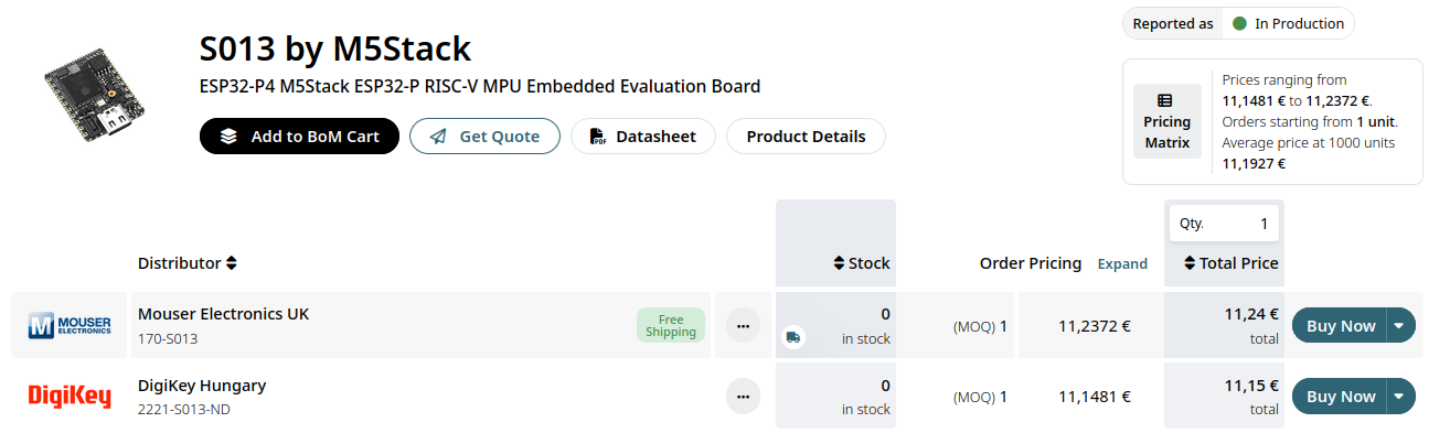 Bildquelle: https://www.oemsecrets.com/compare/S013
Dieter S. schrieb im Beitrag #8075106: > Falls der Chip nicht gesperrt ist könnte man darüber die Firmware > auslesen. Ich gehe (leider) aber davon aus, dass er gesperrt ist, und ich würde daher auch vermuten
ausgeliefert, aber damals wurde sie noch vor dem Flashen entschlüsselt, weil der Bootloader ein stinknormaler AT90S1200 (später ATtiny2313) mit einer AVR109-Firmware war. Also ja, ich kann mir mal anschauen, ob sie das auch heute noch so machen (und man mithin einen jungfräulichen SAMD21 damit flashen kann),
Behauptungen .... Keine Anworten bzw. Eingehen auf Nachfragen zur Klärung .... ---> Don't feed the troll(s).
. > Keine Anworten bzw. Eingehen auf Nachfragen zur Klärung .... > > ---> Don't feed the troll(s). Und völlig /inhaltsleere/ Posts, der "schon sehr viel mit PLLs gearbeitet" haben will. Davon sehe hier nichts. Nicht mal Vorschläge zu interessanten Bausteinen. I don't feed /AllesUnfug's/
Ich benutze den Assembler schon seit Jahren. Bisher konnte ich von AT90S1200 bis ATmega16 damit alles programmieren. Aber in den Include Dateien für diese Controller stehen die fehlerträchtigen Directiven auch nicht drin. Ich habs mir jetzt einfach gemacht und die entsprechenden
C-Style-Direktiven (#define usw.) kennt er nicht (avra auch nicht, aber kann sie immerhin ignorieren). S. L. schrieb im Beitrag #8045985: > avrasm32 kenne ich nicht; ich arbeite mit dem avrasm2 avrasm2.exe ist bei neueren Versionen des Atmel/Microchip Studio dabei und sollte daher mit den aktuellen
EN= 5V Soft-start Time tSS — 750 — µS EN Low to High, 90% of V OUT; Note 4 — — Thermal Shutdown Die TSD 150 C Temperature Die Temperature Hysteresis T — 10 — C SDHYS Note 1: 3.3 K resistive load, OUTV(1 mA). 2: For VIN> VOUT, OUT will
applied to theTVS without operation V Breakdown Voltage -- Maximum voltage that flows though theTVS at a specified test current (I ) BR T V Clamping Voltage -- Peak voltage measured across theTVS at a specified Ippm (peak impulse current) C IR Reverse Leakage Current -- Current measured at V R VF Forward
CHARACTERISTICS DRIVER LOW-TO-HIGH PROPAGATION DELAY TIME DRIVER HIGH-TO-LOW PROPAGATION DELAY TIME vs vs s FREE-AIR TEMPERATURE n FREE-AIR TEMPERATURE – 55 – 90 e R = 0 e i S V CC = 3 V i R S 0 T 50 T 85 VCC = 3.6 V a l e e D 45 D 80 o i a 40 V = 3.3 V a g CC a 75 VCC = 3.3 V p p r 35 r P V = 3.6 V P 70 g
Hi! Benötigt wird DIL40. Ich hätte sonst auch AT89S... als DIL da. Roger P. schrieb im Beitrag #7981985: > Will die wegwerfen.... Ach so. :o) Versuch es doch hier im Markt! Gruß Jobst
Videotextdecoder ist. Das wird aber spätestens beim verifizieren auffliegen. Ich teste hier mit AT89S52. Gruß Jobst
in the photopeak pulse height is measured by changing the photopeak count rate from 10 000 s to 1000 s . If the photopeak pulse height at a count rate of 10 000 s is -1 -1 given by A and that at 1000 s by B, the variation rate (D STS) is given by the following equation. This value is about ±
and shall be located within the shaded Q 0.015 0.060 0.38 1.52 6 area shown. The manufacturer’s identification shall not be used S1 0.005 - 0.13 - 7 as a pin one identification mark. o o o o 2. The maximum limits of lead dimensions b and c or M shall be α 90 105 90 105 - measured at the centroid
Martin S. schrieb im Beitrag #7955707: > Auf jeden Fall keine schlechte Idee, sich mit dem verwaisten Knowhow zu > beschaeftigen, Bei Hobbys ist die Sinnfrage meist nutzlos. Martin S. schrieb im Beitrag
im Beitrag #7955797: > CUDA lernen ist klüger. Habe neulich erst damit begonnen, CUDA auf einem AT90S1200 zu implementieren. Sobald ich damit fertig bin, dann sofort auf 'nem Tiny.
, damit sie nicht militärisch genutzt werden können. Ein Beispiel: https://portal.u-blox.com/s/question/0D52p0000CIel9sCQB/are-all-ublox-gnss-receivers-able-to-operate-at-altitudes-above-60000-feet-without-modifications-in-the-distant-past-gps-receivers-were-inoperative-above-that-altitude-due-to-dod-concerns
sie auf der sicheren Seite sind), findet man sehr verschiedene Werte (18000 km, 60000 ft, 1000 kn, 1200 mph, 512 m/s u.a.). Die in dem Wikipedia-Artikel genannte Grenzhöhe von nur 12000 m tanzt sehr aus der Reihe und ist wohl eher falsch. https://en.wikipedia.org/wiki/Coordinating_Committee_for_Multilateral_Export_Controls
Microchip Technology FITNESS FOR PURPOSE. Microchip disclaims all liability Incorporated in the U.S.A. arising from this information and its use. Use of Microchip Analog-for-the-Digital Age, Application Maestro, CodeGuard, devices in life support and/or safety applications is entirely at dsPICDEM,
set the toler- ance on the simulator for solving equations. As an steps allowing for a better chance at converging example, in IC’s the current can be in µA, but if • Check the “Use GMIN stepping to improve con- simulating a switching power supply the currents vergence” option if its available. This will
side of the bridge rectifier for fast AC reset) and the UNDER/OVER INPUT VOLTAGE pin to enable this S: Has Taken No P: Not Switching Control? S: Doesn’t Take Control functionality. This function can be disabled by shorting the UNDER/ OVER INPUT VOLTAGE pin to SOURCE pin. At power-up, after the primary
Stephan S. schrieb im Beitrag #8006028: > Angesichts der Mengen dürfte es sich um ein gewerbliches Angeot handeln. Geht's Dich was an oder willst Du nur, weil Dir langweilig ist, Rechthaber ohne Grund spielen
17.000 XOR-Gattern vor? OK, ein PRN-Generator mit sehr langer Folgedauer würde mir einfallen. P.S. Bist du der Ralph T. aus HB mit den Senderfotos?
1 deutet auf +0,1 Sekunde DUT Differenz. Zur Erklärung: MSF60 hat vier Austastlückenlängen: 0,5 s für Minutenbeginn 0,1 s für logisch Null im A- und B-Code 0,2 s für logisch Eins nur im A-Code 0,3 s für logisch Eins im B-Code Werden nun logisch Null im A-Code und logisch Eins im B-Code gesendet
ehe Atmel das bei den neueren AVRs geschnallt hat, obwohl ich das schon 1996 bei der Vorstellung des AT90S1200 moniert hatte. Außerdem wird noch ein Schieberegister 74HC164 zur parallelen Ansteuerung des LCD benötigt. Das LCD ist mit einem Standard HD44780 Controller und hat 2 * 16 Zeichen Darstellung.
voltage -0.3~10 V pin voltage -0.3~10 V pin voltage -0.3~10 V CE pin voltage -0.3~10 V BAT pin current 1200 mA PROG pin current 1200 μA Maximum junction temperature 145 ℃ Operating ambient temperatureopa -40~85 ℃ Storage temperature str -65~125 ℃ Soldering temperature and time +260(Recommended 10S) ℃ Caution
required. Strings and images can be placed with pixel accuracy. Text and graphics can be combined at any time. Different character sets can be used at same time. Each character set and the images can be zoomed from 2 to 8 times and rotated in 90° steps. With the largest character set, the words and
tare memory function, all containers subsequently placed on the scale will be automatically tared at >70% of the weight of the first container. * = factory setting 3–14 Totalizing Totalizing S/a key Code 2 7 2* Read Totalizing Memory s/r Symbol displayedΣ With the totalizing application you can totalize
interlaced composite signal. The above examples of timing information are provided for models operating at fixed horizontal frequencies of 15.75 kHz. Model can be either TTL or composite video operating at 15.7 kHz. VGA Signal For a display that operates at 31.4 kHz horizontal and 60 Hz vertical 640 x 480
Timinig generator OSC2 S e a e n a a o at LCD drive power supply circuit c Common COM1 to r driver COM176 u t V V C C V B V C C C C V V V V V V i c 1 1 O A i 2 2 E E R R S C M C U 1 + - T S 2 + - + - F F H H L T o o C o o L
CS CS CS 8 www.irf.com ( )&(PbF) IR2156 S 1600 6 1400 5 1200 4 1000 F A ( 800 m T C 3 C I 600 2 400 1 200 0 0 0 0.5 1 1.5 2 2.5 3 40 80 120 160 200 DT µ S) Frequency (KHz) Graph 1. CT vs Dead Time (IR2156) Graph 2. CC vs Frequency (IR2156) 120
more swing high, thus inhibiting the functions of gates A, B and C in figure 4. Gate periods of 0.1 s, 1 s, and 10 s are sync gate, and, via gate N38, it also available at output 1 of IC14, IC1S and Figure 5. This simplified diagram shows how enables the clock input of FF2, so that, the control pulses
Microchip Technology Inc. DS40146F-page 15 HCS361 6.0 PROGRAMMING THE HCS361 by clocking in 16 bits at a time, followed by the word’s complement using S3 or S2 as the clock line and PWM When using the HCS361 in a system, the user will have as the data in line. After each 16-bit word is loaded, a to program
169 43 S900 T 90 111 TP26 B 18 76 TP76 B 81 10 TP127 B 120 14 TP177 B 46 102 R1013 T 85 30 R1127 T 183 55 S901 T 61 110 TP27 B 16 77 TP77 B 71 20 TP128 B 179 45 TP178 B 44 105 R1014 T 102 40 R1200 T 188 96 TP28
filter hybrid circuit that sharply limits the bandwidth of the signal applied to the A/D Converter. At 3–9 AM700 Audio Measurement Set Service Manual Theory of Operation 96 kHz, the roll off is better than 90 dB. A servo circuit following the filter (U122 and associated components), looks at the DC offset
ES shuntingefect{inputimpe - dancePM2519). Tthe 0 Sooke"ND connect VOLTAGE 1208ANDRIENOEANDRNGD V E S r e a p e Tvv]q [1 D90mV 0 10 v} 1411 | 90°mV 1STa m s BRO r v|1 | m v 1 eama o . 9o - - 9 V c“UNCTON.OFhwires pce : asmoV E S R1210 7 260 e auoees NOTE: Measuremeznertoisthelowsocket. 4 5 4.24, Voc
plus vite que 2,5 cm/sec.) le long de la fente. 6. L’émission de radiation des micro-ondes doit être S HA RP mW cm 2 2 mW cm Microwave leakage measurement at 5 cm distance Mesure d’une fuite de micro-ondes à une distance de 5 cm R-733 - 25 DIAGRAMMES SCHEMATIQUES REMARQUE: CONDITION DU FOUR 1. Porte fermée
plus vite que 2,5 cm/sec.) le long de la fente. 6. L’émission de radiation des micro-ondes doit être S HA RP mW cm 2 2 mW cm Microwave leakage measurement at 5 cm distance Mesure d’une fuite de micro-ondes à une distance de 5 cm R-733 - 25 DIAGRAMMES SCHEMATIQUES REMARQUE: CONDITION DU FOUR 1. Porte fermée

 Bild
Bild