706114/1.png) Bildquelle: Infineon. ### Microchip EVB-LAN8670-USB-D bzw EV62B92A – USB-zu-10BASE-T1S-Konverter Microchip bietet mit dem LAN8670 seit einiger Zeit einen PHY an, der ein Ethernet-Interface für 10BASE-T1S zur Verfügung stellt. Mit dem EVB-LAN8670-USB-D gibt es ein Evaluationsboard
neuen C15-/C16-Mikrocontroller zu erleichtern sucht. ### Microchip dsPIC33A Digital Power Starter Kit 4 – Evaluationsboard mit integrierter Testlast Wer „ernsthaft“ mit Leistungselektronik experimentiert, hat normalerweise
sauber zurücksetzt und dann synchron startet. Für PWM ist für den synchronen Start das Register PWM_BASE+EN zuständig. (Seite 1088) Für PIO ist für den synchronen Start das Register PIO[012]_BASE+CTRL zuständig. (Seite 939)
jedenfalls. Das gefilterte PWM-Signal sieht abschnittsweise ziemlich übel aus. In der LUT ist ein 16Bit Sinus abgelegt. Raus kommt so was wie im Bild. Der Tiefpass besteht aus einer Power-Induktivität mit 64µH und der C = 1µF TU2 Folie von Wima. Last ist R = 15 Ohm. Beim Bild ist gelb low-side
Mains connection 12 Mains system fuse 13 Temperature display 14 Temperature symbol 15 Time function 16 Lock 17 Optical control check 18 Temperature buttons 19 Fixed temperature display 20 Special functions 21 Funnel insert 22 Soldering tip compartment 23 Cleaning element WD 1 (M) / WD 1000 (M) 3-18 E
AT -2801FX Fast Ethernet PCMCIA Fiber Adapter Card A T-2801FX/xx-001 PC Interface Key Features 100BaseFX 32-bit Ethernet adapter PC card standard release 8.1 and 68 pin connector • 100Mbps Fiber port with SC or ST connector Mobile ConnectivityThrough Fiber Network Connector AlliedTelesis’ AT-2801FX PCMCIA
Snubberless™ D PAK T1650-600G 50 mA Snubberless™ 2 D PAK DS2114 - Rev 11 page 15/18 T1610, T1635, T1650, BTA16, BTB16 Ordering information 3.2 Ordering information Table 9. Ordering information Order code Marking Package Weight Base qty. Delivery mode BTA16-600BRG BTA16-600B BTA16-600BWRG BTA16-600BW BTA16-600CRG
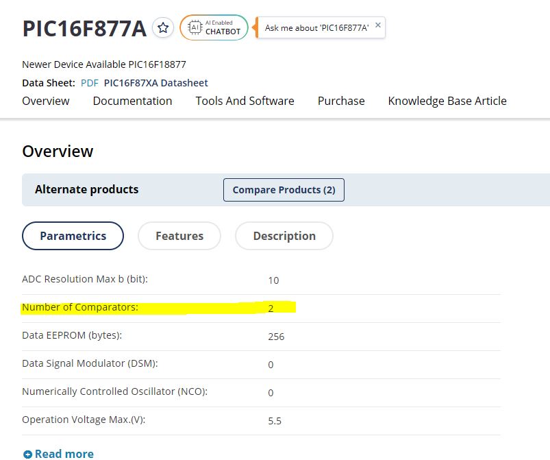
PIC16F87A AI Enabled CHATBOT Ask me about 'PIC16F87A' Newer Device Available PIC16F187 Data Sheet: PDF PIC16F87XA Datasheet Overview Documentation Tools And Software Purchase Knowledge Base Article Overview
Building C object esp-idf/esp_coex/CMakeFiles/__idf_esp_coex.dir/src/coexist_debug_diagram.c.obj [16/1714] Building C object esp-idf/esp_coex/CMakeFiles/__idf_esp_coex.dir/src/coexist_debug.c.obj [17/1714] Building C object esp-idf/esp_wifi/CMakeFiles/__idf_esp_wifi.dir/src/wifi_default.c.obj [18/1714
Glaskolben: 15mm Länge Glaskolben: 43mm Sensorfläche: 11x30mm² 45° Sensor: Durchmesser Glaskolben: 16mm Länge Glaskolben: 35mm Sensorfläche: 9x14mm²
der Geschwindigkeit (keine Grenzfrequenz!) gibt es zur ORP50 die Angaben: 9 MOhm (mit 300 V) nach 16 Stunden in Dunkelheit, 3400 Ohm nach 15 Minuten mit 50 lux Widerstandsabfallzeit auf 7 kOhm: 350 msec nach 16 h in Dunkelheit Widerstandsanstiegszeit auf 25 kOhm: 75 msec ausgeschaltet nach 15 min
schon so. Ich könnte das noch verständlicher zeichnen, wenn es in KiCad Rundsteckverbinder (TRU GX16) gäbe.
schrieb: >> Ich könnte das noch verständlicher zeichnen, wenn es in KiCad >> Rundsteckverbinder (TRU GX16) gäbe. > > Im Schaltplan ist die Art des Steckverbinders eher zweitrangig. Es gibt GX16 nicht in THT...
MD1 H H L L H H L L H H L L H H L L MD1 MD0 H L H L H L H L H L H L H L H L LINES 2 4 6 8 10 12 14 16 4 8 12 16 20 24 28 32 V−DOTS 16 32 48 64 80 96 112 128 32 64 96 128 160 192 224 256 1 SCREEN 2 SCREENS MD2 H L H L MD2 Input Pins for selection of number of columns MD3 H H L L MD3 Columns 32 40 64 80
jawohl kaum auf zuzeichnen gedenkt und deshalb den Re corder ebenfalls abstoppt. Die Datenzeile 16 Oie notwendige Datenmenge für diese Kennungen kann vollständig inder Zeile 16 der 21 nichtzur Bildsignalübertragung »Jstudioseiwirdder2 -K a n a l-M=M5B aktuellAdreDbereichscode benötigten freien Zeilen
genannte Ladegerät nicht, vermute aber, dass dies genauso daneben liegt wie mein Graupner Ultramat 16S. Der Grund bei meinem Graupner, liegt im Messverfahren, dieses ermittelt den Innenwiderstand anhand des Spannungsabfalls bei unterschiedlichen Ladeströmen. Dein YR1030 / YR1035 sowie mein RC3563
genannte Ladegerät nicht, vermute aber, dass dies > genauso daneben liegt wie mein Graupner Ultramat 16S. > Der Grund bei meinem Graupner, liegt im Messverfahren, dieses ermittelt > den Innenwiderstand anhand des Spannungsabfalls bei unterschiedlichen > Ladeströmen. > Dein YR1030 / YR1035 sowie mein
Printout/Record Configuration 2–12 Data Record Output 2–13 Additional Functions: Menu Access Function 2–16 Beep Tone (Acoustic Signal) 2–16 Blocking the Keys 2–16 Blocking the Number Keys 2–16 Universal Switch for Remote Control 2–17 Power-On Mode 2–17 Display Backlighting 2–18 Automatic Shutoff (Battery
Bild von mir entgegen zu kommen: nix Whatsapp (*) :) *: Aber Threema, Foto, Fahrplan, Knowledge Base, KI uvam.
häufig auch ein Sicherungswiderstand ist im Bereich von 10-33 Ohm, der Strom auf Werte zwischen 10...16A begrenzt. Wer hat nun den höheren Inrush-Current?
Section 5.6.7. Æ Screw the "empty-tape duct assembly" (Item no.: see Section 5.2) on the machine base (2 screws each on left and right, M4 x 16). -> Tighten the screws to the correct torque -> see Table in Fig. 5.4.2. WARNING The following check can only be conducted from the bottom of the cutter after
0xAA. This register is read/write. Memory Space Configuration Register Name Index Definition Memory base address 0x40 Read/write value indicating the selected memory base address bits[23:16] for bits[23:16] descriptor 0 memory descriptor 0. This is the Boot Prom Space. Memory base address 0x41 Read/write
input coupling is set to DC. – Check for leading edge without over- or undershoot and – Set time base to 0.1 μs/div. flat square wave top. – Check for fast leading edge without over- or undershoot and flat square wave top. – Press CH I/II pushbutton (IN position). 16. CH II: Attenuator – Connect the 25
eher keine Wolken/Niederschlag.... Hat jemand eine Erklärung wie das Zustande kommt? Aktuell ( 16.7.2026 13:00 www.windy.com -> Wetterradar sieht man es noch )
vorgeschrieben gecheckt, ob er auf diesem Band senden darf. * https://fritz.com/apps/knowledge-base/fritz-box-7490/1349_5-GHz-Funknetz-gelegentlich-deaktiviert-Radar-Signal
l RV32: 32-bit architecture, general-purpose register bit width of 32 bits l E: RV32I subset, only 16 general-purpose registers supported l C: Supports 16-bit compression instruction l XW: 16-bit compression instruction for self-extending byte and half-word operations Note: To further improve code density
C The WDT time-out flag after: 1s F8 100 101X-0011-X C Time base clock output:8Hz, The WDT time-out flag after: 1/2s Time base clock output:16Hz, F16 100 101X-0100-X C The WDT time-out flag after: 1/4s Time base clock output:32Hz, F32 100 101X-0101-X C The WDT time-out flag after: 1/8s Time base clock output:64Hz, F64 100 101X-0110-X C The WDT time-out flag after: 1/16s Time base clock output:128Hz, F128 100 101X-0111-X C Yes The WDT time-out flag after: 1/32s TEST 100 1110-0000-X C Test mode
EC47650 ELECT 47UF/50V 8 C166,168,170,171,173,174,175,177 3 IC4580L IC NJM4580L 1 IC35 3 JK5031 XLR BASE 4 MIC1,2,3,4 3 JK6353-02-250 MIC BASE 19 J1~J19 3 LD-LG2040 GREEN LED 12 LED2,3,11,12,13,14,15,16,17,18,19,20 3 LDLT0311-41 RED LED 7 LED1,5,6,21,22,23,24 3 LDLY2040A YELLOW LED 5 LED4,7,8,9,10 C217,223,238,240,244,246,250,252,256,258,261,262
with Base series bases. To prevent damage to the device, do not stack Core2 v1.3 with any Base series expansion base. • When stacking Core2 v1.3 with M5 modules, you will need to remove the battery bottom
Protokolle: [c] ISO 14443A, ISO 14443B, FeliCa™, and ISO 15693 protocols [/c] ### Atomic Audio-3.5 Base Wer Sprachinformationen ein- oder ausgeben muss und dafür ein Audio-Frontend benötigt, wird von M5Stack mit der in der Abbildung gezeigten Atomic Audio-3.5 Base bedient.  0x3004 51 b1 e5 db magic 0x51B1E5DB 0x3008 00 01 b0 00 SD_SIZE = 0x1B000 0x300C 00 00 00 87 FWID = 0x0087 ``` Because the struct is only 16 bytes there is no SD-ID or version
état initial lorsque l’appareil est mis en marche. R-733 - 16 DESCRIPTION DU CIRCUIT LSI LSI(IZA855DR) Les signaux E/S du LSI(IZA855DR) sont décrits dans le tableau suivant. No.debroche Signal E/S Description 1-3 SEG21- SORTIE Borneinutilisée. SEG23 4 COM1 SORTIE
500 m 0x88,0x13,0,0 8 km 0x80,0x38,1,0 750 m 0x4c,0x1d,0,0 12 km 0xc0,0xd4,1,0 1 km 0x10,0x27,0,0 16 km 0x00,0x71,2,0 1.5 km 0x98,0x3a,0,0 24 km 0x80,0xa9,3,0 A Digital Interface for a Lowrance Broadband Radar 9 Table 4 Register values for ▯lters and preprocessing 0 1 2 3 4 5 6 7 8 9 10 Automatic Gain
MCU-PERIPHERAL INTERFACE 8 high 8 low 8-bit buffer 8 8 8 8 8 8 8 8 i w i w i w i w EXEDG h l h l h l h l 16 16 BIT OUTPUT OUTPUT INPUT INPUT 1/2 FREE RUNNING COMPARE COMPARE CAPTURE CAPTURE 1/4 REGISTER REGISTER REGISTER REGISTER 1/8 COUNTER 1 2 1 2 COUNTER ALTERNATE 16 REGISTER 16 16 CC1 CC0 TIMER INTERNAL
Harald K. schrieb im Beitrag #8066720: > Dann zeig' doch mal eine 16-TB-SSD, die man sich gleich zweifach für das > heimische NAS leisten kann ... 2-fach? In ein NAS gehören 8-16 HDs!
Peter N. schrieb im Beitrag #8066839: > 2-fach? > In ein NAS gehören 8-16 HDs! Wenn das primäre Ziel ist, eine exorbitant teure und lärmintensive Heizung zu betreiben, dann mag das sein. Für alle anderen Anwendungsfälle reichen eine oder meinetwegen auch zwei Platten

 Bild
Bild
 Bild
Bild
 Bild
Bild
 Bild
Bild
 Bild
Bild
 Bild
Bild

 Bild
Bild