-
PDF
device.pdf
Need WPGM51 V5.70 INTEL MPU/MCU 87L51FB NONE No Need WPGM51 V5.70 INTEL MPU/MCU 87L51FC NONE No Need WPGM51 V5.70 INTEL MPU/MCU 87L52 NONE No Need WPGM51 V5.70 INTEL MPU/MCU 87L54 NONE No Need WPGM51 V5.70 INTEL MPU/MCU 87L58 NONE No Need
-
PDF
Schaltplan.pdf
Power Supply Unit with Integrated LED Driver Power Supply Unit with Integrated Led Driver A01 A01 L410 ! L402 D402 BFS3510A SB3200DO-201 CN5_1M99 VLED ANODE_R GND1 1 GND_AL EPC1515/55uH 2 ! L401 +12V +12V_AL EPC1515/55uH D401 3 GND_AL SB3200DO-201 4 CN2_1316 D414 ANODE_L +12V_AL 1 0 0 0 R427 5 GND_AL
in „Defekte Netzteilplatine Philips TV 55PFL7606“ · Analoge Elektronik und Schaltungstechnik ·
-
Datei
usb.c
=================================== // For devices with 2x16 bits/word access schema // (e.g. STM32L0x2, STM32L0x3, STM32F04x, STM32F072, STM32F078, STM32F303xD, STM32F303xE, STM32G4xx) #define UMEM_SHIFT 0 #define UMEM_WIDTH uint16_t // For devices with 1x16 bits/word access schema // (e.g. STM32F103
in „STM32G484 USB CDC Code läuft nur wenn mit <= -O1 kompiliert“ · Mikrocontroller und Digitale Elektronik ·
-
Thread
STM32G484 USB CDC Code läuft nur wenn mit <= -O1 kompiliert
[c] // EP3 = Int (unused) #define Ep3TxOffset 384 // 8 Bytes at 384 #define Ep3RxOffset 292 // 8 Bytes at 392 [/c] Die 292 ist falsch, der Kommentar dahinter hat offenbar die richtige Zahl.
viel schneller abschließen können. Zusammenfassung der finalen Änderungen: Falschen Offset (292) korrigieren: [c] #define Ep3RxOffset (392) /* 8 Bytes ab 392 */ [/c] 2x volatile hinzufügen: [c] #define EpTable ((volatile struct TEpTableEntry *) (USB_RAM + (EpTableOffset<<UMEM_SHIFT
Mikrocontroller und Digitale Elektronik ·Georg M. · ·37 Antworten
-
PDF
Motorola_MC44353_MC44354_MC44355_1998.pdf
Temperature Range Package CC MC44353DTB TSSOP–20 Osc 6 15 RFOut OscGnd 7 14 ModGnd MC44353DW SO–20L SndFil 8 13 VideoIn MC44354DTB TSSOP–20 SndTun 9 12 VCCA TA = –0 ⋅o +80⋅C Pre–Em 10 11 AudioIn MC44354DW SO–20L MC44355DTB TSSOP–20 (TopView) MC44355DW SO–20L This document contains information on a
in „Pollin ist pleite :-(“ · Offtopic ·
-
PDF
siplace-s27hm.pdf
h F h h h a t b u h t m a y i , h n ) ( l t t e ( l t 3 3 ( . g f , 5 u u u N e l g s i e r 1 l T ( c h M r f a 9 r f U V W e F n r 9. F T T T 1 2 3 4 g h s d r d r 3 m a e d a a H c e l l l F c e l l l t a d w F re a e g E e t c r f s r f M
in „Siplace 80 Potentialverteiler“ · Mikrocontroller und Digitale Elektronik ·
-
Datei
disassebled_original_working.asm
2b jmp 0x5708 ; 0x5708 <__vector_35> 00000290 <__trampolines_end>: 290: 4e 41 sbci r20, 0x1E ; 30 292: 4e 49 Address 0x00000292 is out of bounds. .word 0xffff ; ???? 00000293 <pstr_inity>: 293: 49 4e 49 54 59 INITY 00000298 <pstr_inf>: 298: 49 4e 46 INF 0000029b <pwr_m10>: 29b: cd cc cc 3d 0a d7 23
in „Bizarrer Firmware crash - ATmega4808. Wie Debuggen?“ · Mikrocontroller und Digitale Elektronik ·
-
Datei
disassebled_minimal_change_crash.asm
2b jmp 0x5736 ; 0x5736 <__vector_35> 00000290 <__trampolines_end>: 290: 4e 41 sbci r20, 0x1E ; 30 292: 4e 49 Address 0x00000292 is out of bounds. .word 0xffff ; ???? 00000293 <pstr_inity>: 293: 49 4e 49 54 59 INITY 00000298 <pstr_inf>: 298: 49 4e 46 INF 0000029b <pwr_m10>: 29b: cd cc cc 3d 0a d7 23
in „Bizarrer Firmware crash - ATmega4808. Wie Debuggen?“ · Mikrocontroller und Digitale Elektronik ·
-
PDF
6ff78f.pdf
FILES ConfidAlesis S8-31-0127-Aal A B C D J J c c c c 11 1 1 h h h h 76 3 2 I I I I n n n n E E E E l l l l IL I L 4 3 2 1 e e e e NN N N 4 3 2 1 EE E E M M M M // / / C C C C A 86 8 6 J J J 4 3 2 1 c U 1 1 9 8 h X 1 0 n A l / J E C J I I 5 T 1 O L e C 2 U H 1 N N - E - N R 2 H R E E ) E ) O 8 N R L
in „Mischpult "Alesis Multimix 8" (Knallen auf allen Ausgängen)“ · Analoge Elektronik und Schaltungstechnik ·
-
PDF
S32K-RM.pdf
Register Offset FTMOPT0 Ch 11.3.1.3.2 Diagram Bits 31 30 29 28 27 26 25 24 23 22 21 20 19 18 17 16 R L L L L L L L L E E E E E E E E K K K K K K K K L L L L L L L L W 3 2 1 0 7 6 5 4 M M M M M M M M F F F F F F F F Reset 0 0 0 0 0 0 0 0 0 0 0 0 0 0 0 0 Bits 15 14 13 12 11 10 9 8 7 6 5 4 3 2 1 0 R L L
-
PDF
ErklearungDriverSimulation.pdf
alias(*)) W(alias(*)) D(alias(*)) NOISE(alias(*)) * Main Circuit D_D1 D OUT MBR340 M_M1 D G 0 0 IRFZ34 L_L1 N25602 D 1uH IC=10 R_RL1 3 N25602 10m V_VDD 3 0 12 R_R1 0 OUT 10 R_RS 1 IN 50 C_C1 OUT 0 1u IC=24 R_RG 2 G 1 X_U1_U1 1 2 3 0 TC1410N_RevA V_VIN IN 0 +PULSE 0 5 50n 10p 10p 500n 1u .END **** FROM LIBRARY
in „Spice Simulation von Treiber TC4229“ · Analoge Elektronik und Schaltungstechnik ·
-
 Bild
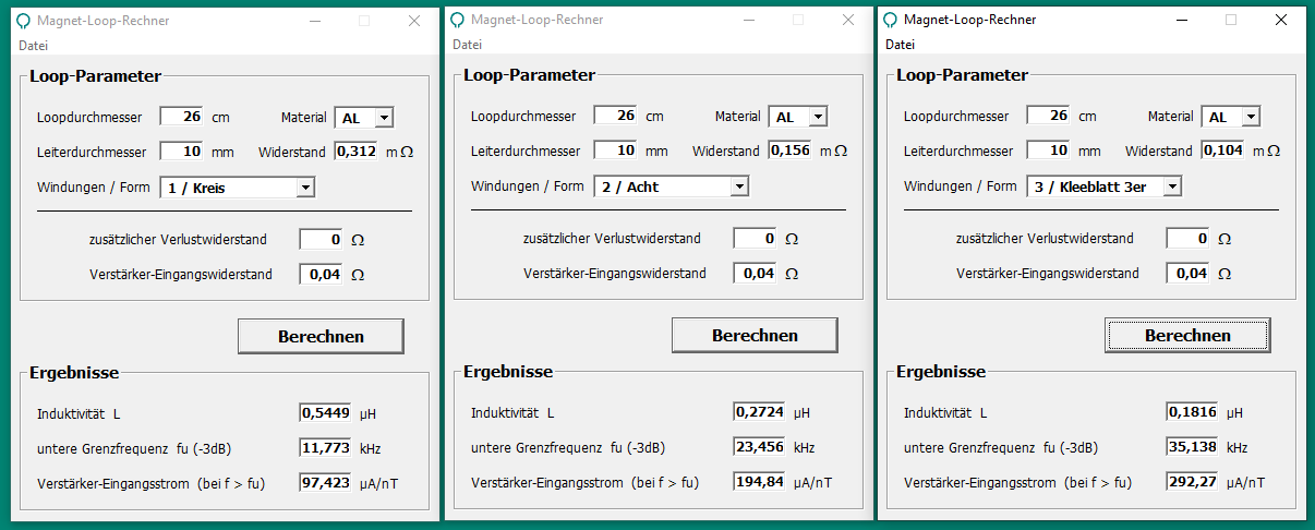
Drei Fenster eines Magnet-Loop-Rechners
zusätzlicher Verlustwiderstand 0 Ω Verstärker-Eingangswiderstand 0,04 Ω Berechnen Ergebnisse Induktivität L 0,5449 µH untere Grenzfrequenz fu (-3dB) 11,773 kHz Verstärker-Eingangsstrom (bei f > fu) 97,423 µA/nT Magnet-Loop-Rechner Datei Loop-Parameter Loopdurchmesser 26 cm Material AL Leiterdurchmesser 10
in „Mini Loopantenne mit NE592N14“ · HF, Funk und Felder · · Screenshots
-
PDF
Orion_Rev_3.0__1_.pdf
2 2 2 25v 2 LD49300PT12R 2 2 16v 2 50v L39 L44 2 1 3 1 2 3P3VA_LT2208_2 MMZ2012R601A 2 NFM41PC204F1H3L L37 1 3 3V3 NFM41PC204F1H3L 2 L36 1 3 3P3VD 2 NFM41PC204F1H3L MMZ2012R601A L40 L22 0E R87 1 3 1 1 2 2 C161 AVDDH 100NF 1 1 2 C159 C156 10NF
in „Suche Firma die für Privat BGA FPGA reballing macht“ · Markt ·
-
PDF
817-A__-M__-S.PDF
temperatures and impeded ventilation and cooling. Conformity to Standards: Approvals: IEC 255-8, IEC 292-1 SEV IEC 255-4, IEC 69 NEMKO SEV, SEN 36 1503 PTB CSA C22.2 No. 14 FI UL 508 CSA Certified Your order must include: Cat. No. of the relay selected with UL Recognized Voltage Suffix Code. 5-5 Bulletin
-
PDF
MC1377.PDF
PLASTIC PACKAGE CASE 738 Internal 8.2 V Regulator 20 1 DW SUFFIX 20 PLASTIC PACKAGE 1 CASE 751D (SO–20L) ORDERING INFORMATION Operating Device Temperature Range Package MC1377DW SO–20L MC1377P TA= 0⋅ to +70⋅C Plastic DIP Figure 1. Representative Block Diagram Quad Decoup VCC VB 19 14 16 18 Oscout Voltage
in „Problem beim FBAS Signal am Amiga 500“ · Analoge Elektronik und Schaltungstechnik ·
-
PDF
NTCLE100E-SERIES_ENG_TDS.pdf
millimeters DERATING AND TEMPERATURE TOLERANCES B T Power derating curve P IV (%) III 100 II H2 I H 1 L 0 - 40 0 55 85 125 150 P d Tamb(°C) Note • Zero power is considered as measuring power max. 1 % of max. power. PHYSICAL DIMENSIONS FOR RELEVANT TYPE (all dimensions in millimeters) H1 R25VALUE BMAX. d H2 MAX. L P T MAX. MIN. MAX. 3.3 to 220 5.0 0.6 ± 0.06 1.0 4.0 6.0 24 ± 1.5 2.54 4.0 330 to 470 k 3.3 ± 0.5 0.6 ± 0.06 1.0 3.0 6.0 24 ± 1.5 2.54 3.0 Revision: 24-Aug-12 2 Document Number: 29049 For technical
in „Defekt bei Sentiotec Sauna/Infrarotkabinen-Steuerung“ · Haus & Smart Home ·
-
PDF
HD66766R.PDF
DB3 DB2 DB1 DB0 R L7 L6 L5 L4 L3 L2 L1 L0 0 C6 C5 C4 C3 C2 C1 C0 0 Figure 5 Status Read Instruction Start Oscillation (R00h) The start oscillation instruction restarts the oscillator from the halt state in the stanAfterode
in „LCD-Modul F51661GNCJU-MLW-AA * Info *“ · Mikrocontroller und Digitale Elektronik ·
-
PDF
Stenorette_2010_SW.pdf
sY gia,ft.9 l a I rar I,toPvtw, E5 t93rg( ll3 ,5t lV'" lvrrnrr{a{r ffi I ! srfoa $PRA Stenorette 2O1O r?tr 1F l:lT + ozoaoN lIN5iN5t0NlNltS!t5!Rt!5 tNPCtloilttlitLtFt f 'l rtil,0N.i{ir[ !m,iqNlt rLi\Pqiltt5tllA5ril
in „Recht auf Reparatur“ · Offtopic ·
-
PDF
NTCLE100E-SERIES_ENG_TDS.pdf
millimeters DERATING AND TEMPERATURE TOLERANCES B T Power derating curve P IV (%) III 100 II H2 I H 1 L 0 - 40 0 55 85 125 150 P d Tamb(°C) Note • Zero power is considered as measuring power max. 1 % of max. power. PHYSICAL DIMENSIONS FOR RELEVANT TYPE (all dimensions in millimeters) H1 R25VALUE BMAX. d H2 MAX. L P T MAX. MIN. MAX. 3.3 to 220 5.0 0.6 ± 0.06 1.0 4.0 6.0 24 ± 1.5 2.54 4.0 330 to 470 k 3.3 ± 0.5 0.6 ± 0.06 1.0 3.0 6.0 24 ± 1.5 2.54 3.0 Revision: 24-Aug-12 2 Document Number: 29049 For technical
in „Gaggenau Backofen NTC-Luftfühler defekt“ · Haus & Smart Home ·
-
PDF
DM8603EP.pdf
DM8603 10/100Mbps3-portEthernetSwitchControllerwithMII/RMIIInterface 7.3.37 STP Control Register (292h) PHY_ADR REG_ADR ABS_ADR 14h 12h 292h Bit ROM Type Default Description 15:1 --- RO 0h RESERVED Write as 0h, ignore when read 0 --- PS,RW 0b STPEN SpanningTreeProtocolEnable 0:Disable 1:Enable 7.3.38
in „[V] DM8203 & DM8603“ · Markt ·
-
PDF
20240122_Waasner_Katalog.pdf
7,60 17,40 3,80 7,6 10.053 EK 20 YEE 2 - 6 dK 20,00 20,00 14,0 6,00 14,00 11,00 3,10.0456,00 1EK 20 L 3,0YEE 2 - 6 dKL 20,00 28,00 14,0 14,00 22,00 11,00 11,00 6,00 14,00 3,00 6,0 10.050 EK 25 L YEE 2 - 8 dKL 25,00 34,00 17,0 17,00 26,40 13,20 13,20 7,60 17,40 3,80 7,6 10.045 EK 20 L YEE 2 - 6 dKL 20,00
in „Was ist aus dem Transduktor geworden?“ · Analoge Elektronik und Schaltungstechnik ·
-
PDF
technical.pdf
slk b i ik bi ik bl=a k bl=a k Figure 4.7: paths in the signal flow graph when connecting ports k and l on the same network ′ Thus the new S-parameter S ij yields to P + P · (1 − L ) + P · (1 − L ) + P · (1 − (L + L + L ) + L ) + P S ij = 1 2 13 3 12 4 11 12 13 21 5 1 − (L 11 + L 12 + L )13 L 21 = P +4