Suchergebnisse für "pwm"
Bild
include <util/delay.h> /* LED PB1 Servor PB4 OCR1C = TOP → Periode definieren OCR1B → Pulsbreite → Servo-PWM | Ereignis | OC1B | | ------------- | ----- | | TCNT1 = 0 | HIGH | | TCNT1 = OCR1B | LOW | | TCNT1 = OCR1C | Reset | */ #define SERVO_PIN PB4 // OC1B #define LED PB1 // Interne LED // -------- Funktionsprototyp
in
„Digispark Klon und PWM Servosteuerung“
·
Mikrocontroller und Digitale Elektronik
·
29.12.2025 12:34
PB1 Servor PB4 OCR1C = TOP → Periode definieren (z. B. 20 ms für Servo) OCR1B → Pulsbreite → Servo-PWM | Ereignis | OC1B | | ------------- | ----- | | TCNT1 = 0 | HIGH | | TCNT1 = OCR1B | LOW | | TCNT1 = OCR1C | Reset | */ #define SERVO_PIN PB4 // OC1B #define LED PB1 // Interne LED // -------- Funktionsprototyp
in
„Digispark Klon und PWM Servosteuerung“
·
Mikrocontroller und Digitale Elektronik
·
29.12.2025 20:05
Bild
USERTCBx USERTCB3
#define CHANNELx EVSYS.CHANNEL3
#define EV_CHANNEL EVSYS_CHANNEL_CHANNEL3_gc
void PWM _shot_init (void)
{
// Setze Port als input event
CHANNELx = PORTx_PINx;
// Verbinde zu event channel 3
EVSYS.USERTCBx = EV_CHANNEL;
// Aktiviere TCB ohne Prescaler
TCBx.CTRLA = TCB_CLKSEL_CLKDIV1_gc
in
„Timer Counter B als PWM Messung“
·
Mikrocontroller und Digitale Elektronik
·
24.02.2026 11:53
·
Screenshots
Bild
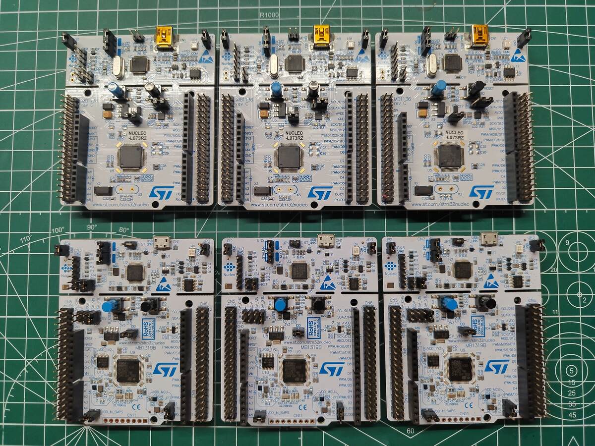
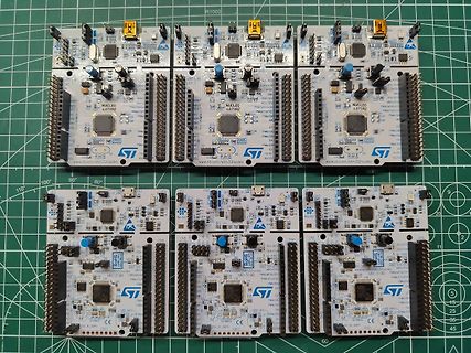
NUCLEO-L073RZ, STM32, www.st.com/stm32nucleo, MB11319B, PWM /MOS/D1, PWM /D2, PWM /D3, PWM /D4, PWM /D5, PWM /D6, PWM /D7, PWM /D8, PWM /D9, PWM /D10, PWM /D11, PWM /D12, PWM /D13, PWM /D14, PWM /D15, PWM /D16, PWM /D17, PWM /D18, PWM /D19, PWM /D20, PWM /D21, PWM /D22, PWM /D23, PWM /D24, PWM /D25, PWM /D26, PWM /D27, PWM /D28, PWM /D29, PWM /D30, PWM /D31, PWM /D32, PWM /D33, PWM /D34, PWM /D35, PWM /D36, PWM /D37, PWM /D38, PWM /D39, PWM /D40, PWM /D41, PWM /D42, PWM /D43, PWM /D44, PWM /D45, PWM /
in
„[V] Diverse STM32 Nucleo Boards“
·
Markt
·
18.08.2026 06:34
·
Platinenfotos
;1 0 0 0 1 ;1 + - ;2 1 0 0 0 ;2 - + ;3 0 0 1 0 ;3 + - ;4 0 1 0 0 ;4 - + ; rechts links ;1) +A +A' PWM 1 PWM 2 ; -B' -B' PWM 4 PWM 4 ;2) -A -A PWM 1 PWM 1 ; +B +B' PWM 3 PWM 4 ;3) +A' +A PWM 2 PWM 1 ; -B -B PWM 3 PWM 3 ;4) -A' -A' PWM 2 PWM 2 ; +B' +B PWM 4 PWM 3 ;-------- ;Ende 2 Phasen Motor !!! ;PWMW = PWM -Mert M2P1
in
„Spielerei mit einem 2- und 5-Phasen-Schrittmotor“
·
Projekte & Code
·
11.02.2026 14:54
;1 0 0 0 1 ;1 + - ;2 1 0 0 0 ;2 - + ;3 0 0 1 0 ;3 + - ;4 0 1 0 0 ;4 - + ; rechts links ;1) +A +A' PWM 1 PWM 2 ; -B' -B' PWM 4 PWM 4 ;2) -A -A PWM 1 PWM 1 ; +B +B' PWM 3 PWM 4 ;3) +A' +A PWM 2 PWM 1 ; -B -B PWM 3 PWM 3 ;4) -A' -A' PWM 2 PWM 2 ; +B' +B PWM 4 PWM 3 ;-------- ;Ende 2 Phasen Motor !!! ;PWMW = PWM -Mert M2P1
in
„Spielerei mit einem 2- und 5-Phasen-Schrittmotor“
·
Projekte & Code
·
20.05.2026 22:55
= current_pwm elapsed = time.time() - ramp_start_time if elapsed >= RAMP_DURATION: current_pwm = target_pwm ramp_start_time = None pwm 0.duty_u16(current_pwm ) return progress = elapsed / RAMP_DURATION new_pwm = int(ramp_start_value + (target_pwm - ramp_start_value) * progress) new_pwm = max(PWM _MIN_HARD, min(PWM _MAX, new_pwm )) if new_pwm != current_pwm : current_pwm = new_pwm pwm 0.duty_u16(current_pwm ) def boost_cycle(t): global target_pwm ,
in
„PWM Webrowser Pumpenmonitor / Steuerung“
·
Mikrocontroller und Digitale Elektronik
·
15.11.2025 21:15
Mode 0 PWMPRD/2 PWMPRD/2 Mode 1 PWM 0PRD/2 PWM 0PRD/2 Frame Frame PWM 0D PWM 0D PWM 0P PWM 0P PWM 0N PWM 0N T NOV TNOV TNOV TNOV Set PWMIF Set PWMIF Mode 2 PWM 0PRD/2 PWM 0PRD/2 Mode 3 PWM 0PRD/2 PWM 0PRD/2 Frame Frame PWM 0D PWM 0D PWM 0P PWM 0P PWM 0N
in
„MCU identifikation/Datenblatt - MC9989A0ZQ“
·
Mikrocontroller und Digitale Elektronik
·
19.11.2025 15:46
PWM Duty Cycle In a Type B implementation the fan will run at minimum RPM for all non-zero PWM duty cycle values less than minimum duty cycle and turn off the motor at 0% PWM duty cycle. See Figure 5. 15 Fan Speed Control Figure 5 Type B Operation, Stay On at Minimum RPM, Off at 0% RPM Speed vs. PWM Duty cycle %of full speed 35 The fan stays on at minimum speed for 30 PWM duty cycle values below the 25 minimum PWM Example Min. duty cycle, and PWM shuts off at 0% 20 PWM duty cycle Example Min. 15
in
„4Pin luefter Spezifikation“
·
Mikrocontroller und Digitale Elektronik
·
27.12.2025 14:43
Noctua PWM specifications white paper Scope of this paper ThescopeofthiswhitepaperistoprovideadetailedtechnicaldocumentationofthePWM (Pulse Width Modulation) speed control features of Noctua’s 4-pin PWM fans.
in
„4Pin luefter Spezifikation“
·
Mikrocontroller und Digitale Elektronik
·
27.12.2025 14:49
5; if (pwm > 255) pwm = 255; delay(50); } // ------------------------- // Minus-Taster // ------------------------- if (digitalRead(minusTaster) == LOW) { potiModus = false; pwm -= 5; if (pwm < 0) pwm = 0; delay(50); } // PWM nur bei Änderung ausgeben if (pwm != letzterPWM ) { letzterPWM = pwm ; statusAusgeben(); } // ------------------------- // PWM ausgeben // ------------------------- if (motorEin) analogWrite(pwm Pin, pwm
in
„Ki Hilft.wenn auch nicht immer“
·
Offtopic
·
26.07.2026 14:37
============================================== // CONRAD WEICHEN-PRUEFGERAET // ARDUINO NANO // // PWM -WECHSELSPANNUNG UEBER DIE VORHANDENE BRUECKE // // Pin 3 = PWM // Pin 2 = Richtung / Polaritaet // // Die vorhandene Hardware erzeugt daraus: // // PWM + LOW // PWM + HIGH // // und damit eine Wechselspannung
in
„Ki Hilft.wenn auch nicht immer“
·
Offtopic
·
08.08.2026 20:42
80 PWM 0DL (95h) Function related to: PWM 0 PWM 0 Duty bit 7~0 PWM 0DL 95.7~0 R/W 00 PWM 1DH (96h) Function related to: PWM 1 PWM 1 Duty bit 15~8 PWM 1DH 96.7~0 R/W 80 PWM 1DL (97h) Function related to: PWM 1 PWM 1 Duty
in
„MCU identifikation/Datenblatt - MC9989A0ZQ“
·
Mikrocontroller und Digitale Elektronik
·
19.11.2025 15:46
EN/PWM rising tLED from ILED= 175 mA 1.5 ms shutdown ILED= 80 mA 1.3 TP1 Turn−On time, EN/PWM rising tLED ILED= 175 mA 600 ns TP2 Turn−Off time, EN/PWM fallingLED I ILED= 175 mA 400 ns I = 80 mA 300 LED T
in
„ATtiny85, energiesparende Schaltung mit PIR und LED FadeIn/FadeOut (Newbie)“
·
Mikrocontroller und Digitale Elektronik
·
16.02.2026 10:54
ADSC)) // Warte, bis Konvertierung abgeschlossen ist ; return ADC; // Gib den ADC-Wert zurück } void PWM _Init() { TCCR0A = (1 << COM0A1) | (1 << WGM01) | (1 << WGM00); // Fast PWM -Modus konfigurieren TCCR0B = (1 << CS01); // Prescaler auf 8 setzen DDRD |= (1 << PD6); // PD6 (Pin 6) als PWM -Ausgang setzen } void SetPWM (uint8_t dutyCycle) { OCR0A = dutyCycle; // PWM Duty Cycle setzen } int main(void) { ADC_Init(); // ADC initialisieren PWM _Init(); // PWM initialisieren DDRH |= (1 << PH6) | (1 << PH5); // PH6 und PH5
in
„ADC-gesteuerte PWM mit LED-Anzeige“
·
Projekte & Code
·
27.02.2026 22:06
Bild
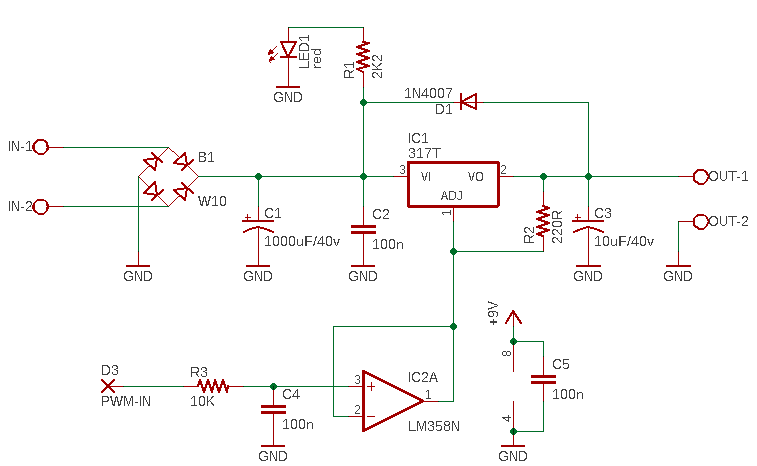
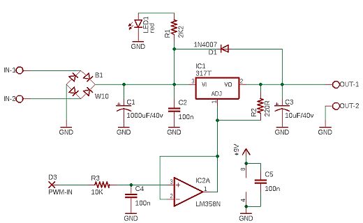
C1 1000uF/40v GND C2 100n IC1 317T VI ADJ VO 2 R2 220R C3 10uF/40v OUT-1 OUT-2 GND +9V C5 100n 4 D3 PWM -IN R3 10K C4 100n 3 + IC2A LM358N 2 1 GND
in
„Suche kleines Modul/Breakout: DCDC von Arduino steuerbar“
·
Mikrocontroller und Digitale Elektronik
·
29.11.2025 23:50
·
Schaltpläne
Bild
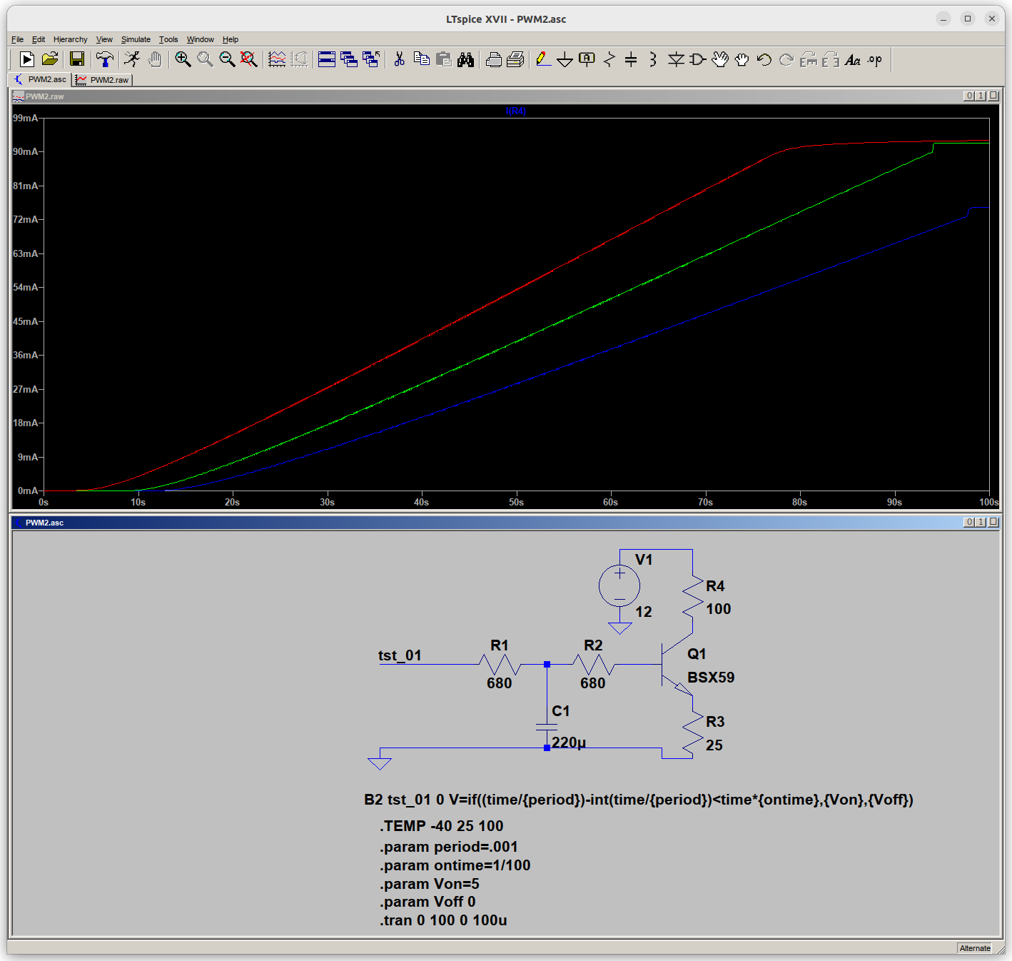
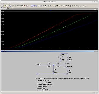
LTspice XVII - PWM 2.asc File Edit Hierarchy View Simulate Tools Window Help 9mA 81mA 72mA 63mA 54mA 45mA 36mA 27mA 18mA 9mA 0mA 0s 10s 20s 30s 40s 50s 60s 70s 80s 90s 100s V1 R4 12 100 Q1 BSX59 R1 R2 680 680 tst_01 C1
in
„Tankanzeige eines E36 mit Mikrocontroller Steuern“
·
Fahrzeugelektronik
·
06.01.2026 21:41
·
Screenshots
Bild
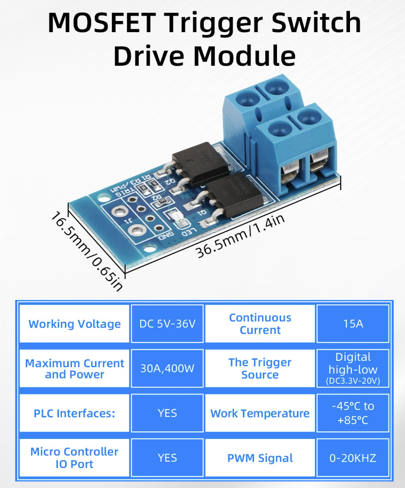
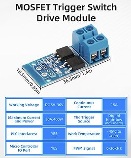
MOSFET Trigger Switch Drive Module 16.5mm/0.65in 36.5mm/1.4in R1 R3 PWM Q2 LED1 LED2 LED3 GND Working Voltage DC 5V-36V Continuous Current 15A Maximum Current and Power 30A,400W The Trigger Source Digital high-low (DC3.3V-20V) PLC Interfaces: YES Work Temperature -45°C to +85°C Micro Controller IO Port YES PWM Signal 0-20KHZ
in
„Mosfet Modul mit PWM ansteuern MKS GEN_L V2.1“
·
Mikrocontroller und Digitale Elektronik
·
04.01.2026 14:08
·
Platinenfotos
Bild
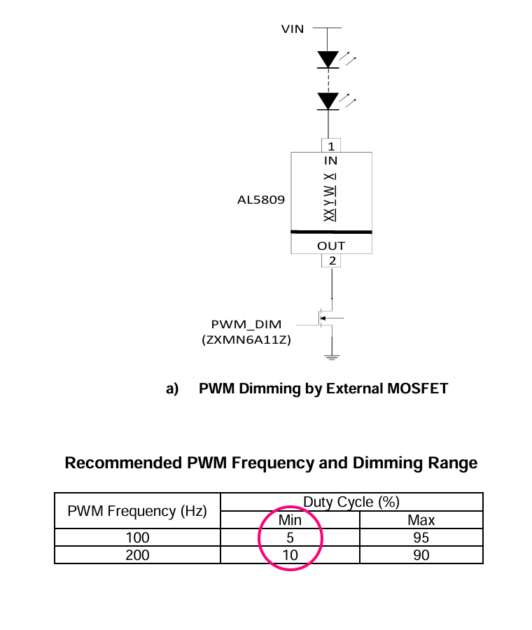
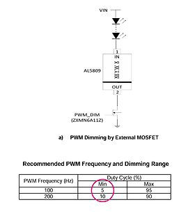
VIN AL5809 IN 1 X Y W X OUT 2 PWM _DIM (ZXMN6A11Z) a) PWM Dimming by External MOSFET Recommended PWM Frequency and Dimming Range PWM Frequency (Hz) Duty Cycle (%) Min Max 100 5 95 200 10 90
in
„ATtiny85, energiesparende Schaltung mit PIR und LED FadeIn/FadeOut (Newbie)“
·
Mikrocontroller und Digitale Elektronik
·
16.02.2026 07:47
·
Screenshots
Bild
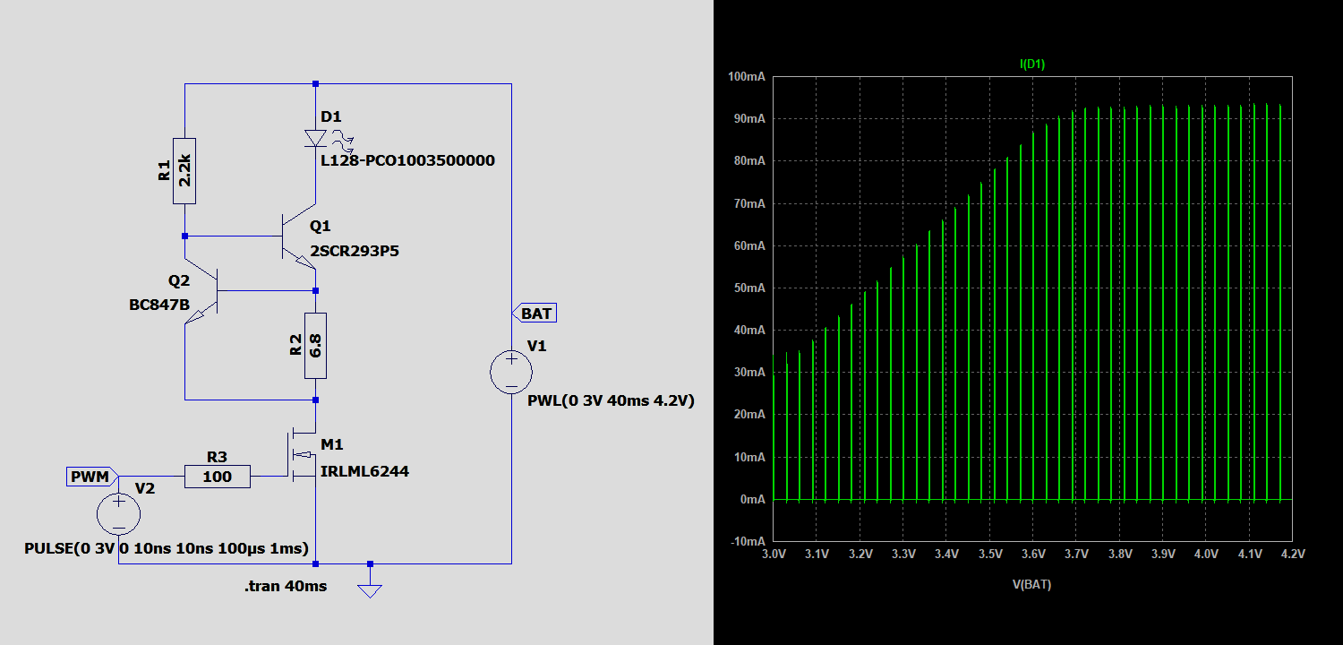
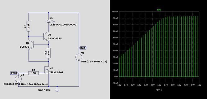
R1 2.2k D1 L128-PCO1003500000 Q1 2SCR293P5 Q2 BC847B R2 6.8 M1 IRLML6244 PWM V2 100 R3 BAT V1 PWL(0 3V 40ms 4.2V) .tran 40ms I(D1) 100mA 90mA 80mA 70mA 60mA 50mA 40mA 30mA 20mA 10mA 0mA -10mA V(BAT) 3.0V 3.1V 3.2V 3.3V 3.4V 3.5V 3.6V 3.7V 3.8V 3.9V 4.0V 4.1V 4.2V
in
„ATtiny85, energiesparende Schaltung mit PIR und LED FadeIn/FadeOut (Newbie)“
·
Mikrocontroller und Digitale Elektronik
·
16.02.2026 18:49
·
Screenshots
< targetADC - 8) { if (pwm 1Value < 255 - pwm Step) pwm 1Value += pwm Step; } else if (adc2 > targetADC + 8) { if (pwm 1Value > pwm Step) pwm 1Value -= pwm Step; } OCR0 = pwm 1Value; // PD7 (Timer2) regelt ADC3 int adc3 = analogRead(A3); if (adc3 < targetADC - 8) { if (pwm 2Value < 255 - pwm Step) pwm 2Value += pwm Step; } else if (adc3 > targetADC + 8) { if (pwm 2Value > pwm Step) pwm 2Value -= pwm Step; } OCR2 = pwm 2Value; } // ----------------------------------------------
in
„Zeigt her eure Kunstwerke (ab 2023)“
·
Projekte & Code
·
20.04.2026 15:33
< targetADC - 8) { if (pwm 1Value < 255 - pwm Step) pwm 1Value += pwm Step; } else if (adc2 > targetADC + 8) { if (pwm 1Value > pwm Step) pwm 1Value -= pwm Step; } OCR0 = pwm 1Value; // PD7 (Timer2) regelt ADC3 int adc3 = analogRead(A3); if (adc3 < targetADC - 8) { if (pwm 2Value < 255 - pwm Step) pwm 2Value += pwm Step; } else if (adc3 > targetADC + 8) { if (pwm 2Value > pwm Step) pwm 2Value -= pwm Step; } OCR2 = pwm 2Value; } // ----------------------------------------------
in
„AUDIOCONTROLLER MSP3400C einfach mit ATMEGA32 ansteuern“
·
Projekte & Code
·
21.04.2026 09:01
. // Clear Timer on Compare Match (CTC) mode is not exactly what we want for PWM // typically. We want Pulse Width Modulator A Enable (PWM 1A). // TCCR1: // CTC1 = 0 // PWM 1A = 1 (Enable PWM A) // COM1A1:0 = 10 (Clear OC1A on Compare Match, Set on 0x00) -> Non-Inverted PWM // CS13:10 = 0010 (Prescaler = 2) TCCR1 = 0; TCCR1 |= (1 << PWM 1A) | (1 << COM1A1) | (1 << CS11); // OCR1C sets the TOP value (Frequency) OCR1C = PWM _TOP; // Initial Duty Cycle 0 OCR1A = 0; // Set PB1 as Output pinMode(PIN_PWM , OUTPUT); } void setup() { setupPWM
in
„Suche Lüfter PWM IC mit Temp. Regelung“
·
Mikrocontroller und Digitale Elektronik
·
05.02.2026 14:51
1 0 1 0 1 0 0 1 FORWARD Full Bridge y 1 M W P 1 1 1 1 1 0 0 1 1 0 BACK Full Bridge e d M 1 1 0 1 1 pwm 1 pwm 1 pwm 2 pwm 2 PWM 1 ->left Two Half 2 PWM 2->right Bridges M W / M 1 1 1 1 1 pwm 1 pwm 1 pwm 2 pwm 2 PWM 1 ->left Two Half W PWM 2 ->right Bridges P Note: The DIR signal is internally synchronized with the
in
„ST L9805-E Motortreiber mit H Brücke und ST7UD05 Kern“
·
Mikrocontroller und Digitale Elektronik
·
26.06.2026 11:02
PWM 0 PWM 0 PWM 0 PWM 0 PWM 0 PWM 0 PWM 0 PWM 0 [7] [6] [5] [4] [3] [2] [1] [0] Default 1 0 0 0 0 0 0 0 6.3.5 PCS1 - Frequency Prescaler 1 PSC1 is used to program the period of the PWM output. The period of BLINK1
in
„[V] 10St. SMD 16-bit LED I2C Treiber NXP_PCA9532PW.112 (TSSOP24) (10€)“
·
Markt
·
16.11.2025 20:48
Weight 143 g Speed 230–1350 rpm, 0 rpm <5% PWM SKU ACFAN00203A rpm Control Pulsweitenmodulation – PWM EAN 4895213702959 Static Pressure 1.0 mmH 2O UPC 840033400756 Airflow 53 cfm | 90.1 m³/h Box Content F12 PWM x 1 Bearing Fluid Dynamic Bearing
in
„2pol-/3pol-Lüfter mit PWM-Betriebsspannung“
·
Analoge Elektronik und Schaltungstechnik
·
24.11.2025 21:09
UHeater=9.7V PWM =205 UR_ADC=865 (Ziel=203) UA_ADC=331 UB_V=12.04 Ramp-Up UHeater=10.1V PWM =213 UR_ADC=867 (Ziel=203) UA_ADC=326 UB_V=12.04 Ramp-Up UHeater=10.5V PWM =224 UR_ADC=862 (Ziel=203) UA_ADC=424 UB_V=11.94 Ramp-Up UHeater=10.9V PWM =229 UR_ADC=865 (Ziel=203) UA_ADC=405 UB_V=12.10 Ramp-Up UHeater=11.3V PWM =239 UR_ADC=864 (Ziel=203) UA_ADC=388 UB_V=12.04 Ramp-Up UHeater=11.7V PWM =246 UR_ADC=864 (Ziel=203) UA_ADC=380 UB_V=12.10 Ramp-Up
in
„Bosch CJ125 mit AVR AT90CAN64“
·
Mikrocontroller und Digitale Elektronik
·
25.07.2026 17:59
1:1 Vorteiler TCCR0A = BIT(COM0A1) + BIT(WGM01) + BIT(WGM00); // Fast PWM einschalten } else { // sonst PWM abschalten TCCR0B = 0x00; // Timer0 abschalten TCCR0A &= ~(BIT(COM0A1) + BIT(WGM01) + BIT(WGM00)); // Fast PWM abschalten PORTB &= ~BIT(PWM _AUSGANG); // Ausgang auf
in
„Ich möchte aus einer Spannung einen binärcode erzeugen“
·
Analoge Elektronik und Schaltungstechnik
·
18.10.2026 12:48
wird ;PORTA, 1 ;Lade Speicherbereich 0 aus EEPROM ;PORTA, 2 ;Lade Speicherbereich 1 aus EEPROM von PWM 1 , PWM 2 ;PORTA, 3 ;Lade Speicherbereich 2 aus EEPROM und PWM 3 , PWM 4 angesteuert ;PORTA, 4 ;Lade Speicherbereich 3 aus EEPROM ;PORTA, 5 ;Lade Speicherbereich 4 aus EEPROM PWM 5 wird nur für 5-Phasen
in
„Spielerei mit einem 2- und 5-Phasen-Schrittmotor“
·
Projekte & Code
·
11.02.2026 14:54
wird ;PORTA, 1 ;Lade Speicherbereich 0 aus EEPROM ;PORTA, 2 ;Lade Speicherbereich 1 aus EEPROM von PWM 1 , PWM 2 ;PORTA, 3 ;Lade Speicherbereich 2 aus EEPROM und PWM 3 , PWM 4 angesteuert ;PORTA, 4 ;Lade Speicherbereich 3 aus EEPROM ;PORTA, 5 ;Lade Speicherbereich 4 aus EEPROM PWM 5 wird nur für 5-Phasen
in
„Spielerei mit einem 2- und 5-Phasen-Schrittmotor“
·
Projekte & Code
·
20.05.2026 22:55
nachgedacht Ich würde das nicht mit zwei GPIOs und Transistoren improvisieren, sondern den µC nur das 1-kHz-PWM erzeugen lassen und damit einen analogen Umschalter zwischen +12 V und −12 V ansteuern. Empfohlene Schaltung +12 V │ ┌─────┴─────┐ µC PWM , 1 kHz ──────►│ SEL │ │ TMUX6219 ├───── 1 kΩ / 1 % ───── CP
in
„saubere Rechtecksignalpegelwandlung 0/5V auf +12/-12V“
·
Mikrocontroller und Digitale Elektronik
·
29.07.2026 22:17
Bild
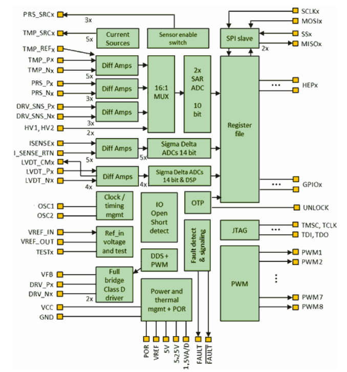
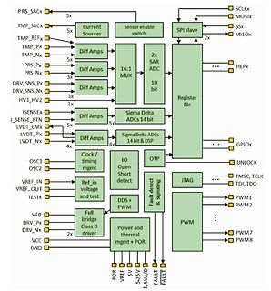
UNLOCK, VREF_IN, VREF_OUT, TESTx, Sigma Delta ADCs 14 bit & DSP, JTAG, TMSC, TCLK, TDI, TDO, DDS + PWM , Fault detect & signaling, PWM 1, PWM 2, PWM 3, PWM 4, PWM 5, PWM 6, PWM 7, PWM 8, VFB, DRV_Nx, DRV_Nx, 2x, Full bridge Class D driver, Power and thermal mgmt + POR, VCC, GND, POR, VREF, 5V, 1.5VA/D, 25V, FAULT
in
„Low End-Mikrocontroller von Renesas und ST, Funkmodule, Amazon Sidewalk uvam“
·
Mikrocontroller und Digitale Elektronik
·
07.03.2026 23:34
·
Diagramme
Bild
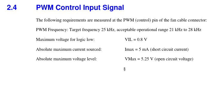
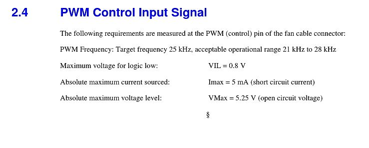
2.4 PWM Control Input Signal
The following requirements are measured at the PWM (control) pin of the fan cable connector:
PWM Frequency: Target frequency 25 kHz, acceptable operational range 21 kHz to 28 kHz
in
„4Pin luefter Spezifikation“
·
Mikrocontroller und Digitale Elektronik
·
27.12.2025 16:55
·
Screenshots
Bild
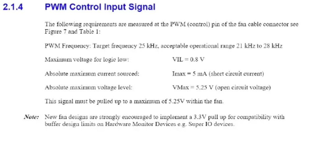
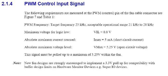
2.1.4 PWM Control Input Signal
The following requirements are measured at the PWM (control) pin of the fan cable connector see Figure 7 and Table 1:
PWM Frequency: Target frequency 25 kHz, acceptable operational
in
„4Pin luefter Spezifikation“
·
Mikrocontroller und Digitale Elektronik
·
27.12.2025 16:56
·
Screenshots
ADSC)) // Warte, bis Konvertierung abgeschlossen ist ; return ADC; // Gib den ADC-Wert zurück } void PWM _Init() { TCCR0A = (1 << COM0A1) | (1 << WGM01) | (1 << WGM00); // Fast PWM -Modus konfigurieren TCCR0B = (1 << CS01); // Prescaler auf 8 setzen DDRD |= (1 << PD6); // PD6 (Pin 6) als PWM -Ausgang setzen } void SetPWM (uint8_t dutyCycle) { OCR0A = dutyCycle; // PWM Duty Cycle setzen } int main(void) { ADC_Init(); // ADC initialisieren PWM _Init(); // PWM initialisieren DDRH |= (1 << PH6) | (1 << PH5); // PH6 und PH5
in
„ADC-gesteuerte PWM mit LED-Anzeige“
·
Projekte & Code
·
23.02.2026 15:01
voltage V IN 38 V L Inductor 4.7 10 µH C I Input capacitor 1 µF C O Output capacitor 1 10 µF FPWM PWM dimming signal frequency 5 100 kHz D PWM PWM dimming signal duty cycle 1% 100% T Operating junction temperature –40 125 °C J 6.4 Thermal Information TPS92360 THERMAL METRIC (1) DCK (SC70) UNIT 5 PINS
in
„VIN am Konstantstromtreiber?“
·
Analoge Elektronik und Schaltungstechnik
·
21.12.2025 18:39
) / 1023.0) * ADC_REF_VOLT * UBAT_DIV_FACTOR; // Kondensationsphase: 2V eff für 5s int CondensationPWM = (int)((2.0 / UBatt_V) * 255.0); if (CondensationPWM > 255) CondensationPWM = 255; if (CondensationPWM < 0) CondensationPWM = 0; analogWrite(HEATER_OUTPUT_PIN, CondensationPWM ); HeaterOutput = CondensationPWM
in
„Bosch CJ125 mit AVR AT90CAN64“
·
Mikrocontroller und Digitale Elektronik
·
25.07.2026 17:44
) / 1023.0) * ADC_REF_VOLT * UBAT_DIV_FACTOR; // Kondensationsphase: 2V eff für 5s int CondensationPWM = (int)((2.0 / UBatt_V) * 255.0); if (CondensationPWM > 255) CondensationPWM = 255; if (CondensationPWM < 0) CondensationPWM = 0; analogWrite(HEATER_OUTPUT_PIN, CondensationPWM ); HeaterOutput = CondensationPWM
in
„Bosch CJ125 mit AVR AT90CAN64“
·
Mikrocontroller und Digitale Elektronik
·
25.07.2026 17:45
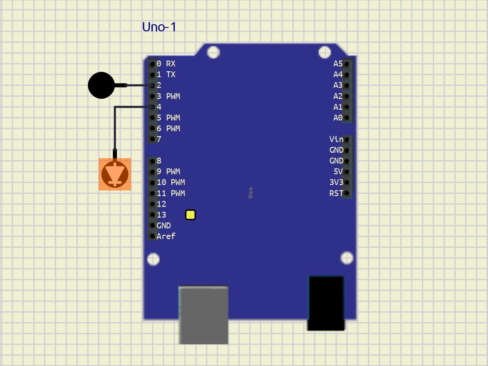
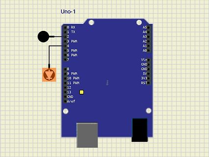
Bild
Uno-1
0 RX
1 TX
2
3 PWM
4
5 PWM
6 PWM
7
8
9 PWM
10 PWM
11 PWM
12
13
GND
Aref
A5
A4
A3
A2
A1
A0
Vin
GND
5V
3V3
RST
Uno
in
„Simulation Arduino Uno-9 in SimulIDE 1.1.0-SR2 at Rev 260312“
·
Mikrocontroller und Digitale Elektronik
·
18.05.2026 00:58
·
Screenshots
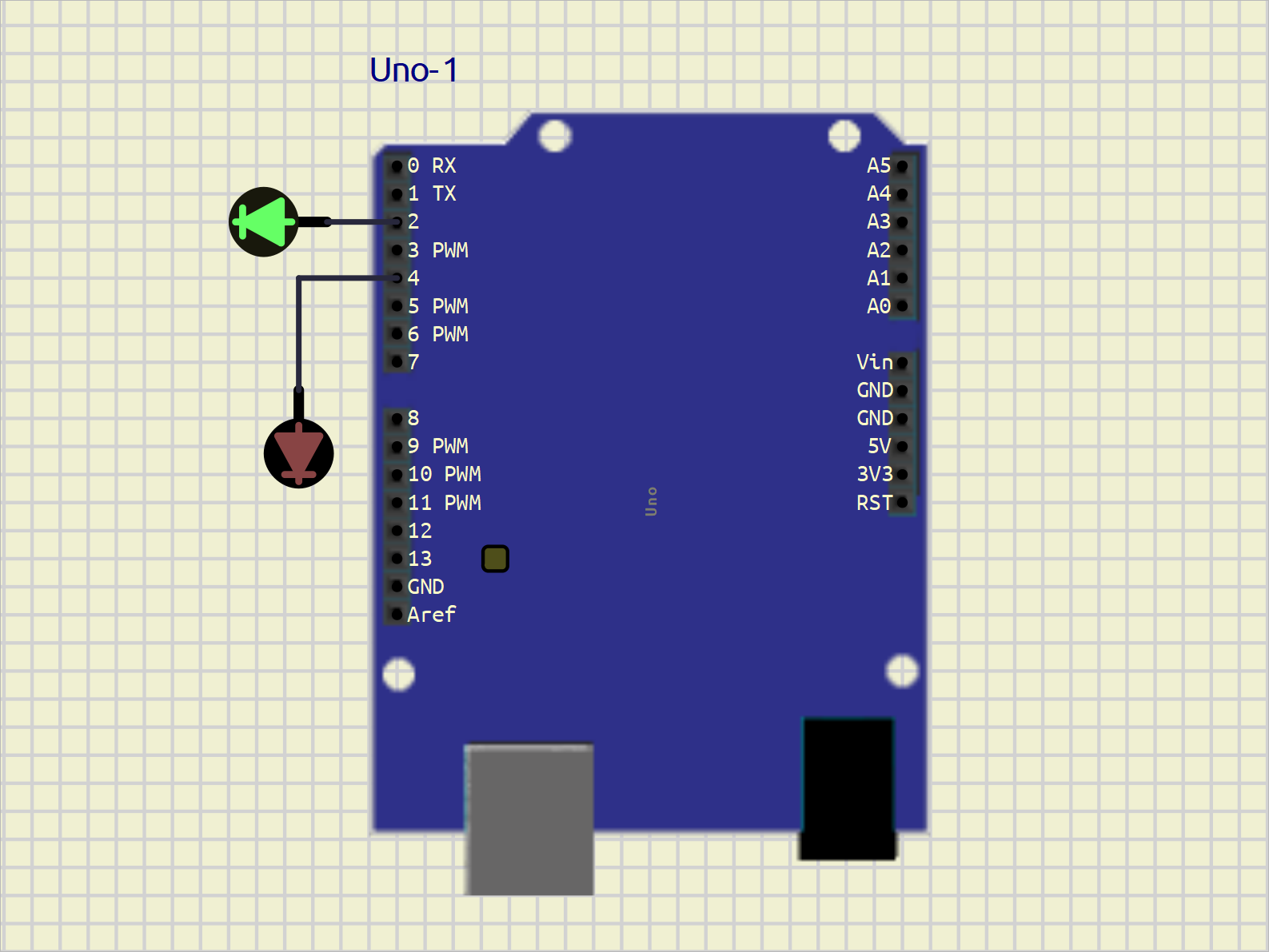
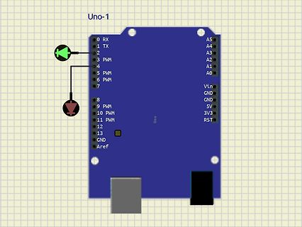
Bild
Uno-1
0 RX
1 TX
2
3 PWM
4
5 PWM
6 PWM
7
8
9 PWM
10 PWM
11 PWM
12
13
GND
Aref
A5
A4
A3
A2
A1
A0
Vin
GND
5V
3V3
RST
Uno
in
„Simulation Arduino Uno-9 in SimulIDE 1.1.0-SR2 at Rev 260312“
·
Mikrocontroller und Digitale Elektronik
·
18.05.2026 01:00
·
Screenshots
alternates per long press. * * Everything runs off the 32.768 kHz ULP oscillator (20 MHz osc stays off). * PWM : TCA0 with PER = 127 -> 256 Hz, 128 levels. While the LED is off the CPU * sits in POWER-DOWN (~0.1 uA, wake on PA1 edge), while on in IDLE so the PWM * keeps running. The PIT (7.8 ms tick, CYC256 of
in
„Lampe Timer deaktivieren“
·
Analoge Elektronik und Schaltungstechnik
·
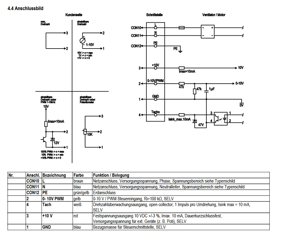
28.07.2026 08:29
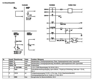
Bild
Drehzahl
1-10V
2
1
10V -> n = max
1V -> n = min
<1V -> n = 0
CON10 L
CON11 N
CON12 PE
3 +10V
2 0-10V/PWM
4 Tach
1 GND
Imax=10mA
47k
1uF
0V
0-10V
Isink_max.10mA
47
15V
12V
100% PWM -> n = max
10% PWM -> n = min
<10% PWM -> n = 0
Nr. Anschl. Bezeichnung Farbe Funktion / Belegung
CON10 L braun Netzanschluss
in
„Sind nicht-isolierte 10V gefährlich?“
·
Analoge Elektronik und Schaltungstechnik
·
04.06.2026 19:04
·
Schaltpläne
Bild
LED Current vs. Duty Cycle
35
30
25
20
15
10
5
0
4V
5V
3V
2V
2V peak PWM
PWM = 20kHz
RSENSE = 10Ω
DUTY CYCLE (%)
100
80
60
40
20
0
in
„ATtiny85, energiesparende Schaltung mit PIR und LED FadeIn/FadeOut (Newbie)“
·
Mikrocontroller und Digitale Elektronik
·
06.02.2026 11:49
·
Diagramme
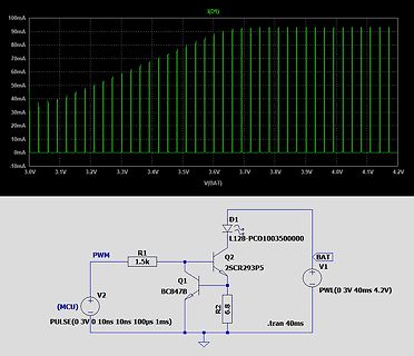
Bild
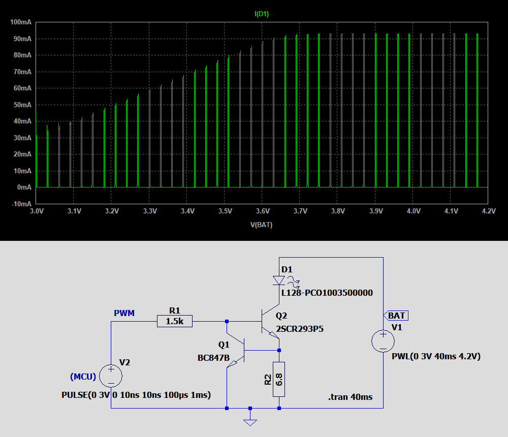
3.1V 3.2V 3.3V 3.4V 3.5V 3.6V 3.7V 3.8V 3.9V 4.0V 4.1V 4.2V V(BAT) D1 L128-PCO1003500000 BAT V1 + PWM R1 1.5k Q2 2SCR293P5 Q1 BC847B R2 6.8 V2 (MCU) PULSE(0 3V 0 10ns 100µs 1ms) .tran 40ms
in
„ATtiny85, energiesparende Schaltung mit PIR und LED FadeIn/FadeOut (Newbie)“
·
Mikrocontroller und Digitale Elektronik
·
17.02.2026 15:08
·
Screenshots
Bild
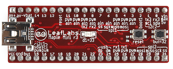
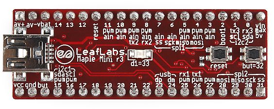
LeafLabs Maple Mini r3
av+ av-vbat 14 13 12 reset pwm ain tx2 rx2 ss sck miso mosi boot1 tx3 rx3 vin max 5v sda i2c d1=33 but=32 reset usb dp dm pwm pwm pwm mosi miso sck ss 23 24 25 26 27 28 29 30 31 22 21 20 19 18 17 16 15 vcc gnd but i2c1 sdasc1 pwm
in
„[S] Maple Mini STM32 Bords“
·
Markt
·
23.12.2025 18:10
·
Platinenfotos
Bild
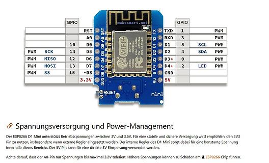
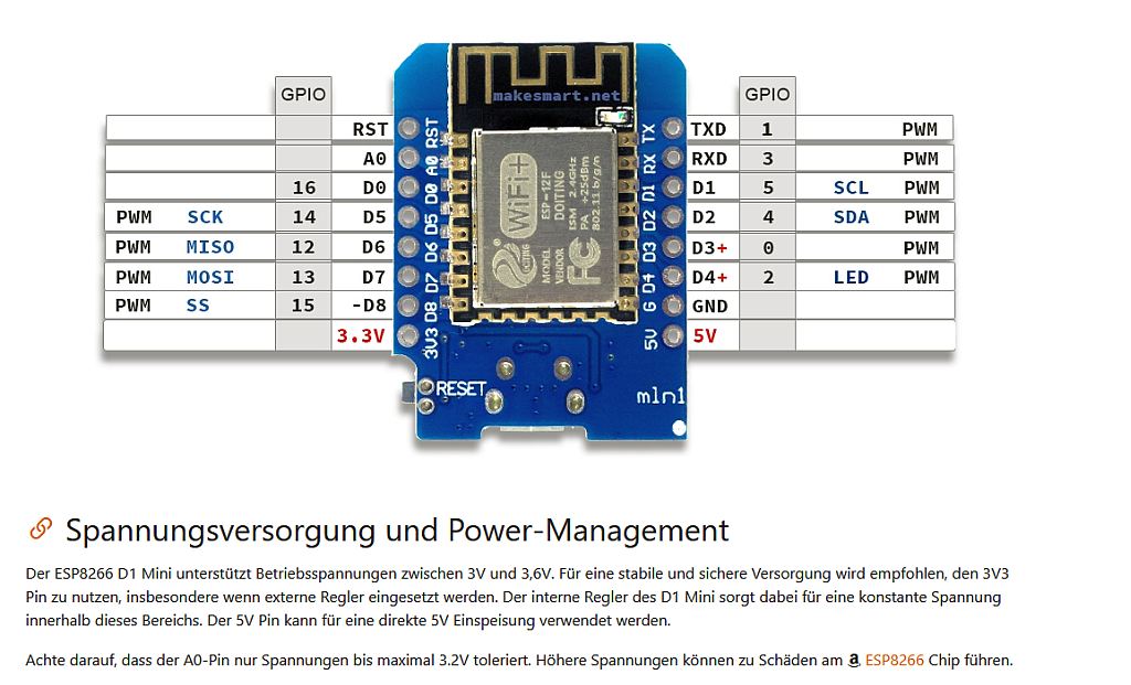
GPIO RST TXD PWM A0 D0 PWM 16 SCK D5 PWM 14 MISO D6 PWM PWM MOSI D7 D2 4 SDA D7 D4 2 LED SS -D8 6 D3 GND 3V3 5V RESET mlnl Spannungsversorgung und Power-Management Der ESP8266 D1 Mini unterstützt Betriebsspannungen
in
„ESP8266 D1 Mini + Relaismodul: Relais bleibt bei D1 dauerhaft eingeschaltet“
·
Mikrocontroller und Digitale Elektronik
·
26.07.2026 10:34
·
Screenshots
Number Symbol Bit Description 0 BACW Blank Alternate Code Word 1 BSEL Baud Rate Selection TABLE 3-1: PWM OPTIONS 2 TXWAK PWM mode: 1/6, 2/6 or 1/3, MOD TXWAK BSEL TE Duty Cycle 2/3 select VPWM mode: Wake-up 0 0 0 400us 1/3-2/3 enable 0 0 1 200us 1/3-2/3 3 SPM Sync Pulse Modulation 0 1 0 200us 1/6-2/6 4
in
„Fehlersuche Funksender Zentralverriegelung Toyota Yaris“
·
Fahrzeugelektronik
·
03.02.2026 14:22
SOT23-5 PT1203 2A, 24V, 350KHz Synchron-Bock DC/DC-Wandler SOP-8 Die PT1101 Hohe Leistungsfähigkeit PWM /PFM Buck DC/DC Konverter-Controller PWM /PFM Step-Down DC/DC Controller SOT23-5 PT1102 Buck DC/DC-Wandler (Eingebauter MOSFET) SOP-8 PT1109 1.5A, 24V, 380Khz Buck DC/DC-Wandler SOP-8 Linearer Regulierungsregler
in
„Was ist das?“
·
Analoge Elektronik und Schaltungstechnik
·
11.04.2026 14:57
================================= // PWM -Ausgang deaktivieren // ============================================================ inline void pwm OutputDisable() { TCCR2A &= ~(1 << COM2B1); TCCR2A &= ~(1 << COM2B0); PORTD &= ~(1 << PD3); } // =
in
„Velux WLC 100 durch Kleinsteuerung ersetzen“
·
Haus & Smart Home
·
08.09.2026 22:31

 Bild

 Bild

 Bild
 Bild
 Bild
 Bild
 Bild
 Bild
 Bild
 Bild
 Bild
 Bild
 Bild
 Bild
 Bild

 Bild
 Bild
 Bild