-
 Bild
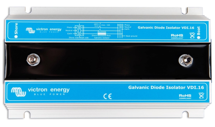
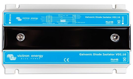
Victron Energy Galvanic Diode Isolator VDI.16
victron energy BLUE POWER Phase Neutral Earth Shore-side Shore Galvanic Isolator max. 16A 30mA Boat Galvanic Isolator Boat ground Phase Neutral Earth Boat Galvanic Diode Isolator VDI.16 RoHS COMPLIANT CE
-
Thread
Historische Bauteile?
in Korea gefertigt wurden. s4008-9.jpeg Bauform: Es sind hochwertige 24-Pin-Keramikgehäuse (Side-brazed CDIP) mit vergoldeten Anschlussbeinchen und einem goldenen Deckel. Diese Bauweise war in den 1970er-Jahren üblich für frühe Mikroprozessor- und Speicherbausteine sowie für Industrieelektronik
-
 Bild
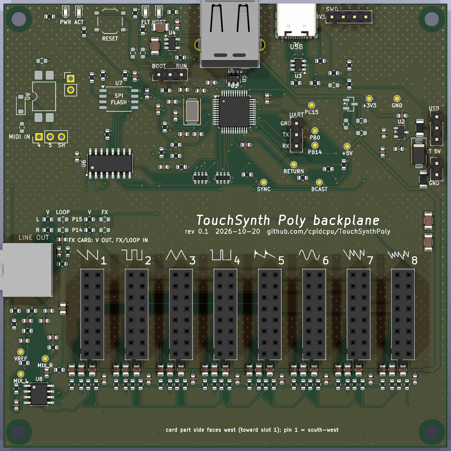
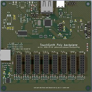
PCB-Layout der TouchSynth Poly Backplane
MIDI IN 4 5 SH USB SWD EV3 +3V3 GND U2 +5V T 5V GND 1 2 3 4 5 6 7 8 V REF MIX_R MIX_L U8 card part side faces west (toward slot 1): pin 1 = south-west TouchSynth Poly backplane rev 0.1 2026-10-20 github.com/cpldcpu/TouchSynthPoly
-
 Bild
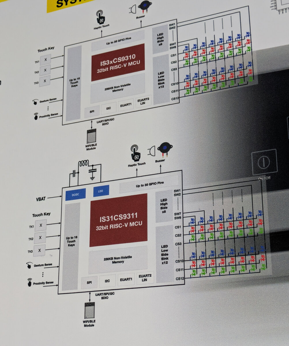
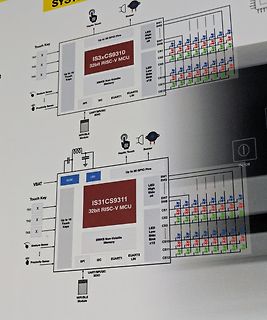
Blockschaltbild eines RISC-V Mikrocontrollers
EUART2 LIN, WIF/BLE Module, LDO, VBAT, Buzzer, Haptic Touch, Up to 35 GPIO Pins, SW1 bis SW8, LED High Side x8, LED Low Side Sink x12, CS1 bis CS12, IS31CS9311 32bit RISC-V MCU
-
 Bild
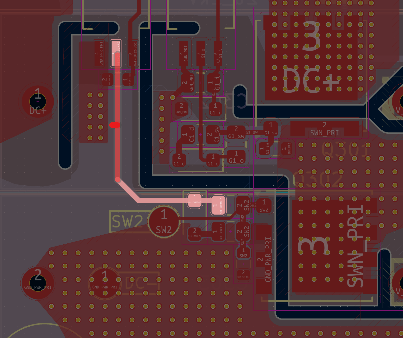
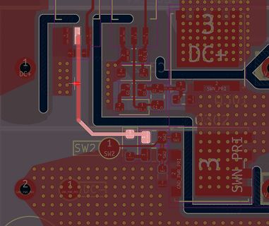
Ausschnitt eines PCB-Layouts
DC+, GND_PWR_PRI, SWN_PRI, G1_t, G1_d, G1_o, G1_sw, SW2, SWN_PRI
-
Thread
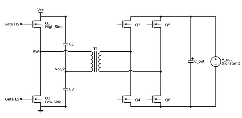
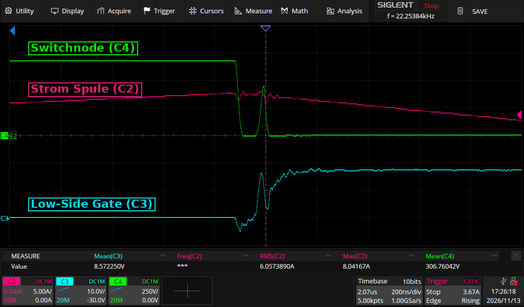
SiC Mosfet bei Dual Active Half Bridge: unerklärliches verhalten bei Halbbrücke / Low Side.
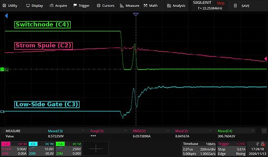
das Low-Side-Gate kurz auf ca. -5 V gezogen (vermutlich Miller über Cgd). 3. Die Switchnode bleibt ca. 60 ns bei 0 V. Genau in dem Moment, in dem das Low-Side-Gate einschaltet, steigt die Switchnode aber nochmal
High-Side ein), tritt das Problem nicht auf. Es betrifft nur die Flanke High-Side aus → Low-Side ein. Was wir schon probiert haben: - Trafo getauscht → keine Änderung - Gatewiderstände erhöht → keine Besserung
-
 Bild
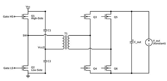
Schaltplan eines Full-Bridge-Wandlers mit Transformator
Vcc, Gate HS, Q1 High-Side, SW, C1, T1, Q3, Q5, V_out (konstant), C_out, Vcc/2, C2, Q2 Low-Side, Gate LS, Q4, Q6
-
 Bild
Oszilloskop-Messung von Schaltknoten, Spulenstrom und Gate-Signal
Cursors Measure Math Analysis SIGLENT Stop SAVE f = 22.25384kHz Switchnode (C4) Strom Spule (C2) Low-Side Gate (C3) MEASURE Value Mean(C3) 8.572250V Freq(C2) *** RMS(C2) 6.0573890A Max(C2) 8.04167A Mean(C4) 306.76042V C2 0.1V/A C3 5.00A C4 0.00A DC1M 10.0V 250V 0.00V Timebase 2.07us 10bits 200ns/div Trigger
-
 Bild
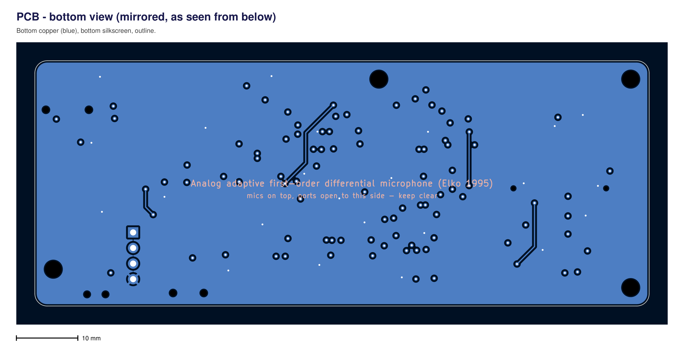
PCB-Layout der Unterseite eines analogen Mikrofon-Adapters
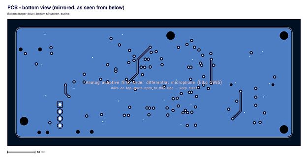
Analog adaptive first order differential microphone (Elko 1995) mics on top, ports open, to this side - keep clear 10 mm
-
 Bild
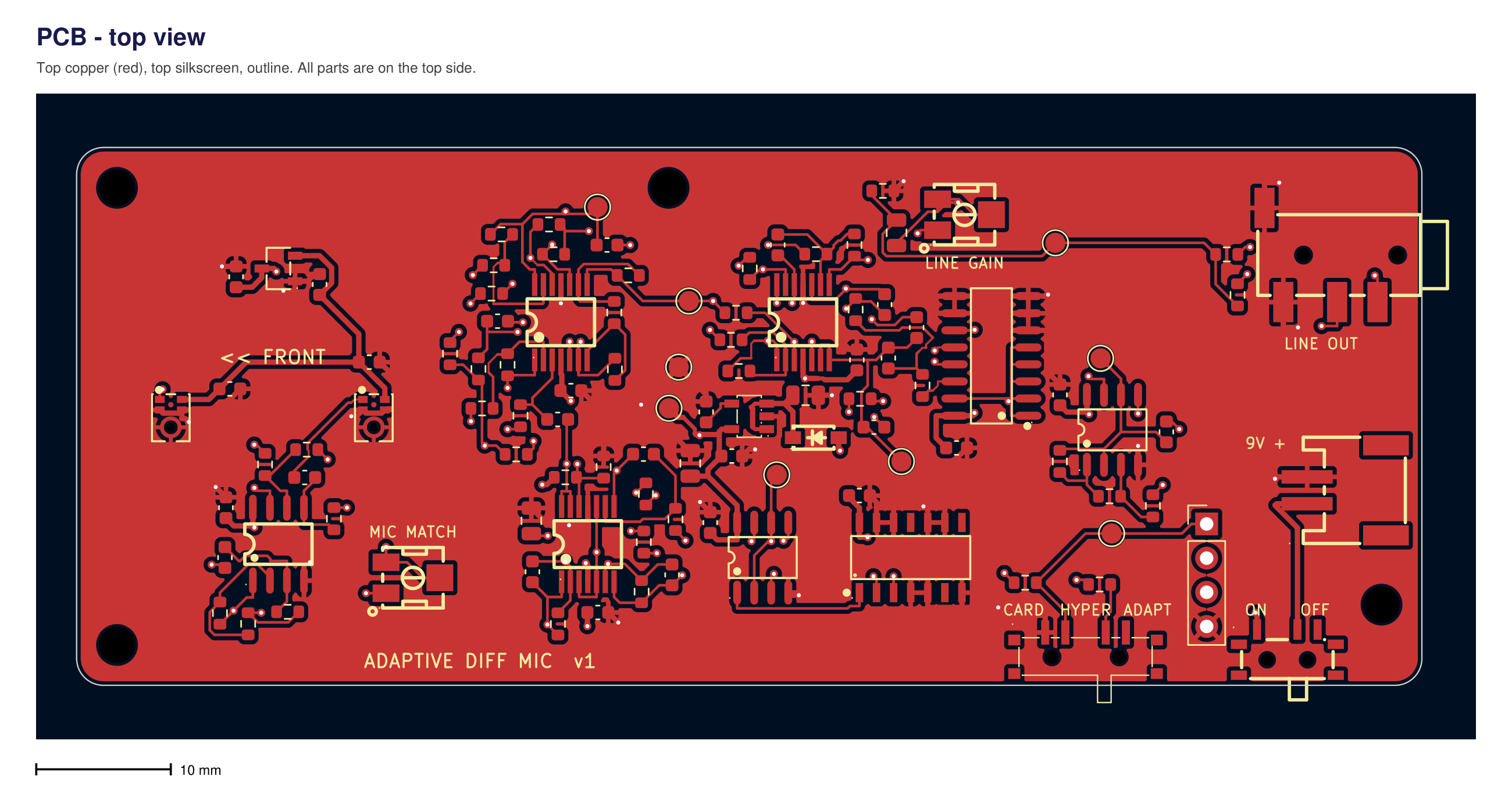
PCB-Layout einer Mikrofon-Schaltung
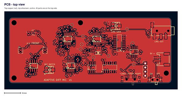
PCB - top view Top copper (red), top silkscreen, outline. All parts are on the top side. FRONT MIC MATCH ADAPTIVE DIFF MIC v1 LINE GAIN LINE OUT 9V + CARD HYPER ADAPT ON OFF 10 mm
-
 Bild
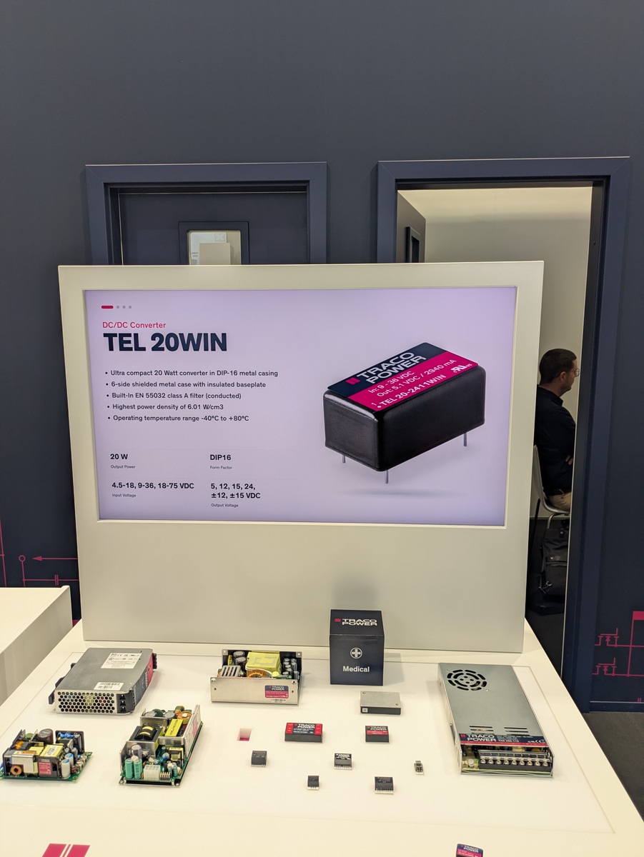
Ausstellung von DC/DC-Konvertern und Netzteilen
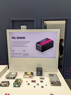
DC/DC Converter TEL 20WIN TRACE POWER Ultra compact 20 Watt converter in DIP-16 metal casing 6-side shielded metal case with insulated baseplate Built-In EN 55032 class A filter Highest power density of 6.01 W/cm3 Operating temperature range -40C to +80C 20 W DIP16 From Factory Output Voltage 4.5-
-
Thread
current transformer - was mißt dieser? SCT010T-D
-10-20-30-50-80a-rated-output-0-333v?_pos=1&_sid=66b146ed5&_ss=r). Diese funktionieren dann wirklich von 0A-Maximalstromstärke. Was meinst Du wohl warum der TO erst ab 0,5A was am Ausgang misst?
https://www.poweruc.pl/products/split-core-current-transformer-sct010t-d-rated-input-5a-50a?_pos=1&_sid=39495f6c2&_ss=r an.
-
 Bild
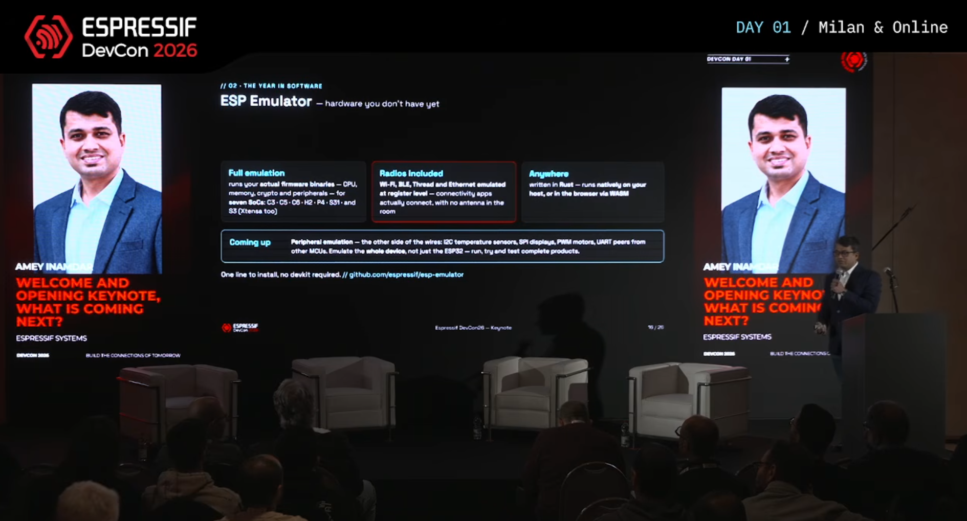
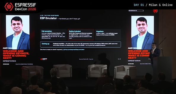
Präsentation von Espressif DevCon 2026
in Rust - runs natively on your host, or in the browser via WASM Peripherals emulation - the other side of wires: I2C temperature sensors, SPI displays, PWM motors, UART peers from other MCUs. Emulate the whole device, not just the ESP32 - run, try and test complete products. One line to install, nodevkit
-
Thread
Bietet hier jemand Chip-Level-Reparaturen als Dienstleistung an?
gun to direct hot air on the pins around the package until package is loose, then push it to the side (this could take a minute or two) > > 4) Remember to also direct air gun to the center of the package where the PowerPad is soldered to the board. Im Bereich Karlsruhe hatte ich mal mit der Firma
-
Thread
ABE Desktop: kostenloses EDA unter Windows, öffnet Eagle-Projekte – Tester für Zusammenarbeit gesuch
– the launcher falls back to X11 (XWayland) as intended. "Zu viele Weiterleitungen": a server-side issue on my side (partner list and marketplace catalogue not published yet), not your system. Nothing to do on your end. radv warning: comes from the Mesa driver for your RX 9060, not from ABE –
-
Thread
I'm looking for a specific and rare HDMI adapter for completing my DIY project
Mario F. schrieb im Beitrag #8106689: > HDMI type A male…and the other side is the micro HDMI FEMALE port https://www.reichelt.de/de/de/shop/produkt/adapter_hdmi_micro_d_buchse_auf_hdmi_a_stecker-145228
already using two HDMI adapters...the same adapters that you suggested...HDMI type A male and the other side micro HDMI FEMALE.
-
 Bild
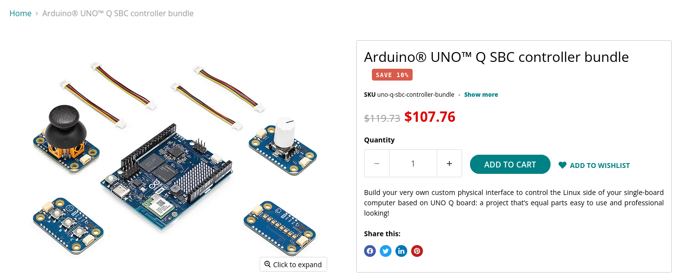
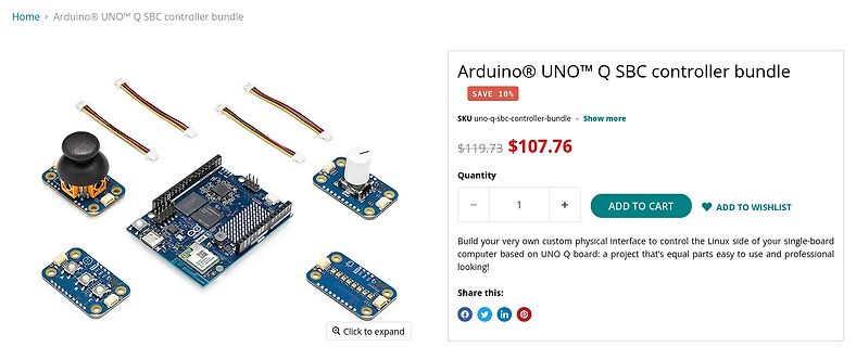
Arduino UNO Q SBC Controller Bundle Set
Quantity ADD TO CART ADD TO WISHLIST Build your very own custom physical interface to control the Linux side of your single-board computer based on UNO Q board: a project that's equal easy to use and professional looking! Share this:
-
Thread
Can two Arduino Unos talk over a 2-wire M-Bus style bus (9V/7V + current reply) across 50 Meters
few questions: 1. Are there simple discrete circuits for this, for both the master and the slave side? 2. Is a 2V swing enough to read reliably with the Uno's ADC, or should I go bigger? 3. Is a series sense resistor the best way to read the slave's current pulses? 4. Could this work over 50
-
Thread
Schaltplan prüfen: Stromversorgung aus Akku mit Spannungsmessung und Taster
vernachlässigbar. Willst du die trotzdem loswerden, schaltest du den Teiler mit einem P-Kanal-FET als High-Side ab statt als Sourcefolger. Das Taster-Latching über EN und die MCU klingt soweit stimmig. Und zu deinem 'nichts Fertiges gefunden': die Kombi Lader plus Buck-Boost für 3,3 V gibt es durchaus als
: > Willst du die trotzdem loswerden, schaltest du den Teiler mit einem > P-Kanal-FET als High-Side ab statt als Sourcefolger. Meinst du wie im Anhang? Wie wird dann das Gate beschaltet? Das müsste ja dann gegen VBAT gehen (im Anhang über R3), damit der Spannungsteiler im Ruhezustand abgeschaltet
-
 Bild
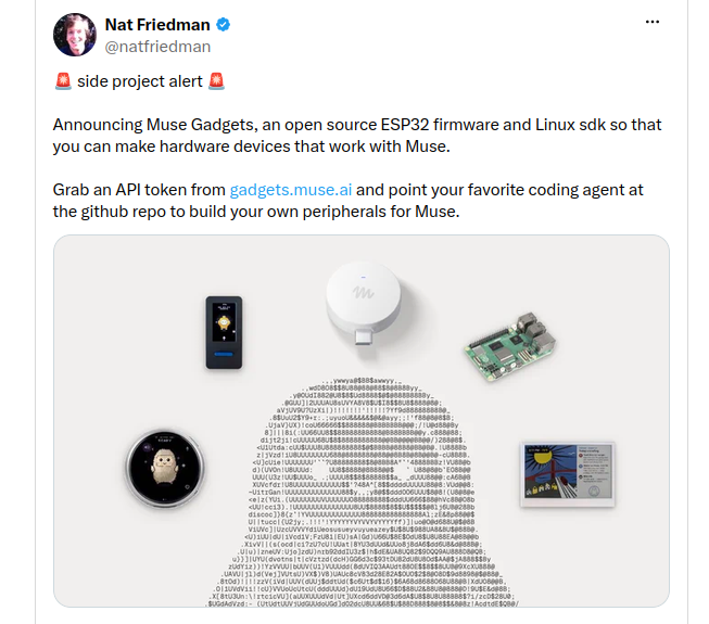
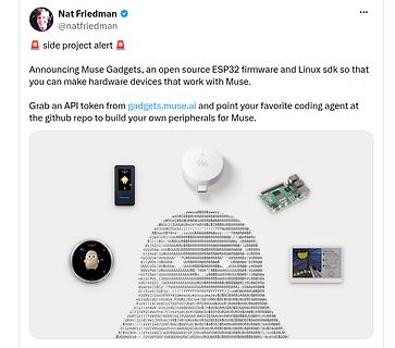
Twitter-Post über Muse Gadgets ESP32 Firmware und SDK
Nat Friedman @natfriedman side project alert Announcing Muse Gadgets, an open source ESP32 firmware and Linux sdk so that you can make hardware devices that work with Muse. Grab an API token from gadgets.muse.ai and point your favorite
-
 Bild
Nahaufnahme einer Leiterplatte mit elektronischen Bauteilen
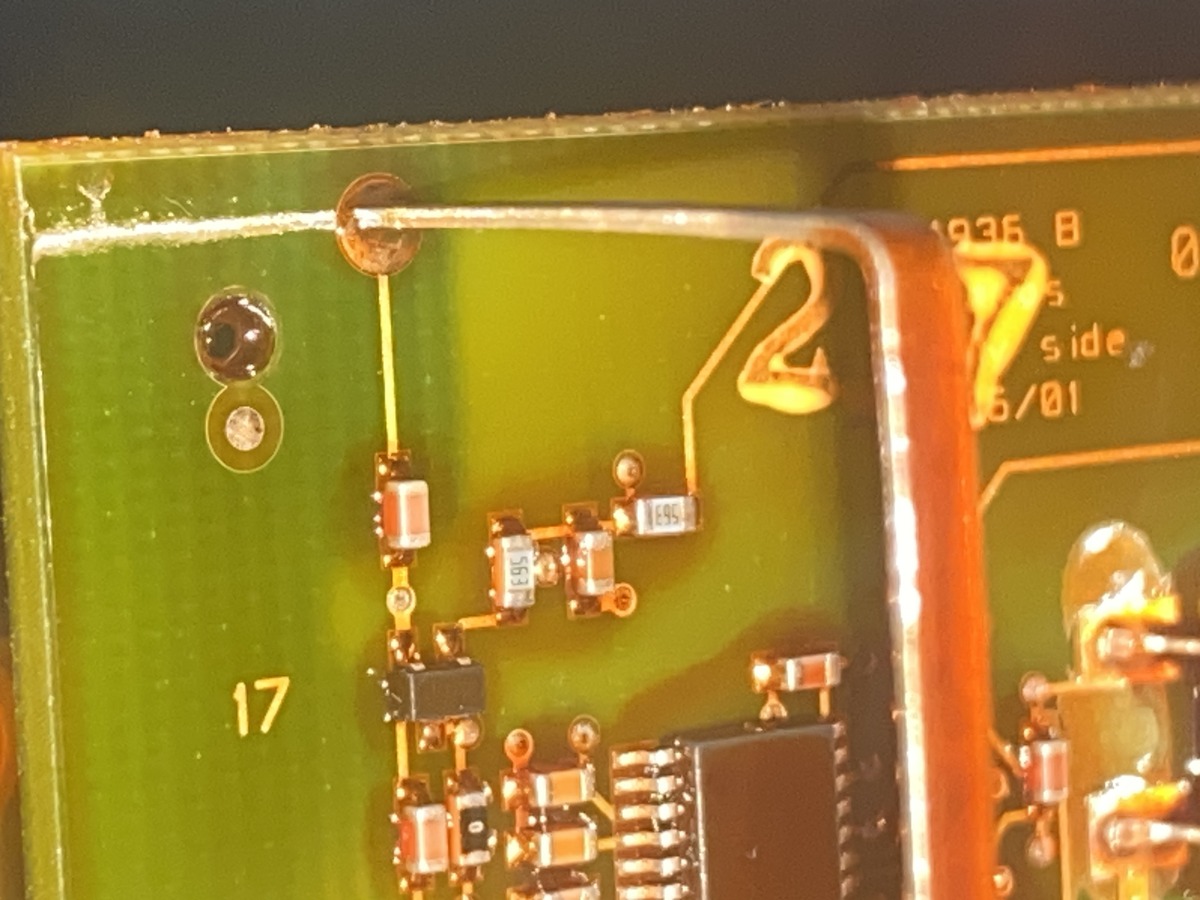
1936 B 27 side 6/01 17 563

-
Thread
Frage zu einer kleinen Transistorschaltung
...ist ja auch unüblich einen P-Channel auf die Low-Side zu setzen...
-
Thread
X86, Sparc, Arm und RISC-V in einem Schwung
immer viel davon) meistens kaum gut getroffen ist. Also meines Wissens hat Paula im Vergleich zum SID kaum/keine Analog-Anteile. Aber Analoges wie ein (abschaltbares) TP-Filter aus OPA war auf dem AMIGA-motherboard, das muss man halt so analog nachbauen. Wobei man sich da nicht an CDTV orientieren sollte
-
 Bild
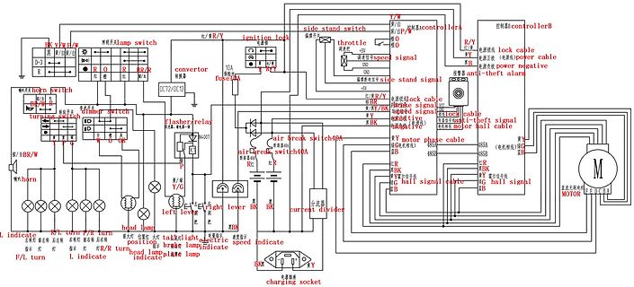
Schaltplan eines Elektrofahrzeugs mit Motor und Steuerung
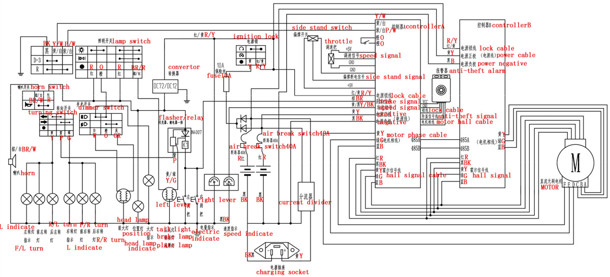
BK Y/W W/W ignition lock side stand switch controllerA controllerB Y/W 控制器B throttle speed signal R/Y 控制器B lock cable R/Y power cable Y/W 控制器B power negative Y/W anti-theft alarm 10A fuse DC72/DC12 air break switch 40A air brake
-
Thread
MachineLogMonitor – Textlogs von RS232, CAN und CAN-Trace-Dateien mehrere gefilterte Ansichten
Signaldekodierung. Nur Textlogs mitlesen, mehrere Sichten gleichzeitig. Technik: Python >= 3.10, PySide6, python-can, pyserial. MIT-Lizenz. Entwickelt und getestet unter Windows. Linux sollte über pyserial/SocketCAN laufen, ist aber ungetestet. **Quellcode und Installation** Das Paket liegt auf
Tippen eines Filters mit vollem Puffer nicht mehr ein. **Wichtig für Python 3.10 und 3.11:** Mit PySide6 6.12.0 kann der Prozess nach einigen tausend Zeilen abstürzen. 0.3.0 bleibt dort deshalb auf PySide6 6.11, ein Update lohnt sich also. ``` pipx upgrade machine-log-monitor ``` bzw. ```
-
Thread
Pi Pico PWM mit Totzeit
nachgestellte PWM startet sauber und läuft auch durch. Nur ab- und zu entsteht entweder auf der High-Side oder der Low-Side ein längerer Puls, der sich natürlich negativ auf das Ausgangssignal auswirkt. Anbei ein Bild was ich meine: - gelb: low side - türkis: high side - lila: (gefiltertes) Ausgangssignal
leerlaufen kann. Sorry, ist mein erster Versuch mit Fifo und PIO. Der PIO-Code [pre] ; GPIO2 = Low-Side, GPIO3 = High-Side ; Systemtakt: 150 MHz .wrap_target ; --- HIGH-SIDE Phase --- pull block ; High-Side-Dauer aus FIFO holen mov x, osr ; Verschiebe in das X-Register
-
Thread
CCD-Sensoren, Analog-FPGAs, Ventuno Q für Profis uvam
area of each pixel, the sensor achieves higher light-collection efficiency than conventional front-side illuminated (FSI) architectures. This results in quantum efficiency (QE) of up to 73% at 550 nm and 15% at 940 nm, improving performance in challenging lighting conditions and near-infrared applications
-
Thread
"Reparatur"-Bericht Samsung TV - RU-Serie - Bootloop wegen CVK-Lines
intensiver werdend (11.jpg); scheinbar haben die 150R da was "rausgebrannt" mit der Linie als side-effect... Fortsetzung folgt...
-
 Bild
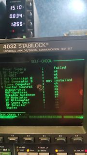
Display eines Stabilock Kommunikations-Testsets mit Fehlermeldung
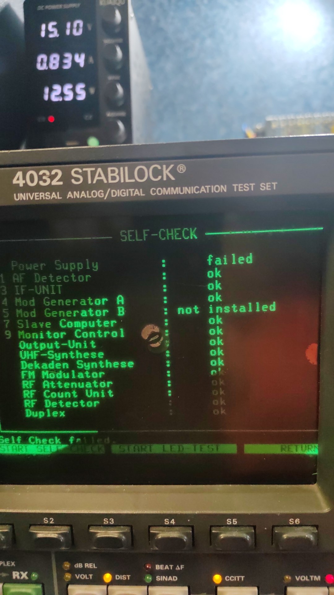
15.10 0.834 12.55 4032 STABILOCK UNIVERSAL ANALOG/DIGITAL COMMUNICATION TEST SET SELF-CHECK Power Supply failed 1 AF Detector ok 3 IF-UNIT ok 4 Mod Generator A ok 5 Mod Generator B not installed 9 Slave Computer ok Monitor Control ok Output-Unit ok UHF-Synthese ok Dekaden Synthese ok FM Modulator ok RF Attenuator ok RF Count Unit ok RF Detector ok Duplex ok Self Check failed. START SELF CHECK START LED-TEST RETURN S2 S3 S4 S5 S6 DUPLEX RX VOLT DIST SINAD CCITT VOLTM
-
Thread
Ordner: Nur-lesbarer Zweitpfad
the "share user folder" in tracking the files. ... The files are not being written to either side(windows or WSA). This seems to be an internal bug with the implementation of "share user folder". The issue, though, is persistent in that it will continue to report incorrect info. ... Again,
-
Thread
Suche Hilfe: Kleines Platinenlayout (12V/20A MOSFET) für JLCPCB gegen Aufwandsentschädigung
den man die ganzen Schutzbausteine herum selbst entwickelt, oder ob man nicht mit einem Smart High-Side-Switch besser bedient ist der das alles schon integriert. Z.B. sowas hier: https://www.infineon.com/part/BTS50015-1TAD https://www.lcsc.com/product-detail/C2150052.html