-
Datei
out.lst
78 00 ' which is 0x. 00000082 <__c.3>: 82: 20 69 6e 20 68 65 78 61 64 65 63 69 6d 61 6c 2e in hexadecimal. ... 00000093 <UART_pszEndOfLine>: 93: 0d 0a 00 ... 00000096 <__init>: 96: 11 24 eor r1, r1 98: 1f be out 0x3f, r1 ; 63 9a: cf e5 ldi r28, 0x5F ; 95 9c: d4 e0 ldi
in „Multiplikation ist zu schnell...“ · Mikrocontroller und Digitale Elektronik ·
-
Datei
Example1_DisplayTest.ino
Wire.setClock(400000); #endif /* USSE_SPI */ // Don't show the logo on boards with small memory #if !defined(__AVR_ATmega328P__) && !defined(__AVR_ATmega168__) showLogo( ); // The showLogo function is a hacky way to get a large bitmap into program space without using <avr/pgspace.h> #endif } void loop() { lineTest
in „Arduino OLED Display Ansteuern & "Hello World" Programme gehen nicht.“ · Softwareentwicklung ·
-
Datei
DCF77_Mega88.c
isr(void) { unsigned int low, high, Timer; /* The register names vary from timer to timer and from AVR to AVR! Have a look at the datasheet of the AVR you're using first. Important note: All 16-bit registers have can only be accessed one byte at a time. To ensure precise timing, a 16-bit temporary register
in „DCF77 Bit0 ermitteln“ · Mikrocontroller und Digitale Elektronik ·
-
Datei
8080int-jmp.asm
... .equ ZFL_S = 7 .equ ZFL_Z = 6 .equ ZFL_H = 4 .equ ZFL_P = 2 .equ ZFL_N = 1 .equ ZFL_C = 0 .equ AVR_T = SREG_T .equ AVR_H = SREG_H .equ AVR_S = SREG_S .equ AVR_V = SREG_V .equ AVR_N = SREG_N .equ AVR_Z = SREG_Z .equ AVR_C = SREG_C ;------------------------------------------------; ; Load table value
in „CP/M auf ATmega88“ · Mikrocontroller und Digitale Elektronik ·
-
Datei
makefile.txt
software. 21. # 22. # make clean = Clean out built project files. 23. # 24. # make coff = Convert ELF to AVR COFF. 25. # 26. # make extcoff = Convert ELF to AVR Extended COFF. 27. # 28. # make program = Download the hex file to the device, using avrdude. 29. # Please customize the avrdude settings below first
in „Problem mit compilen mit headerdatei usw“ · Mikrocontroller und Digitale Elektronik ·
-
Datei
main.c
--------------------------------*/ #include "config.h" #include "usart.h" #include "networkcard/enc28j60.h" #include "stack.h" #include "timer.h" #include "cmd.h" #include <stdint.h> #include <stdlib.h> #include <stdio.h> #include <stdbool.h> #include <avr/io.h> #include <avr/eeprom.h> #include <avr/pgmspace.h> #include <util/delay.h> #include <avr/interrupt.h> #include <string.h> #include "com74hc595.h" #include "R_TRIG.c" #if USE_ADC #include "analog.h" #endif #if USE_HTTPD #include "httpd.h" #include "base64.h" #endif #if USE_WOL #include "
in „Interrupt Variable übergeben“ · Mikrocontroller und Digitale Elektronik ·
-
Datei
main.c
"com74hc595.h" #include "R_TRIG.c" #include "config.h" #include "usart.h" #include "networkcard/enc28j60.h" #include "stack.h" #include "timer.h" #include "cmd.h" #include <stdint.h> #include <stdlib.h> #include <stdio.h> #include <stdbool.h> #include <avr/io.h> #include <avr/eeprom.h> #include <avr/pgmspace.h> #include <util/delay.h> #include <avr/interrupt.h> #include <string.h> #include "main.h" #if USE_ADC #include "analog.h" #endif #if USE_HTTPD #include "httpd.h" #include "base64.h" #endif #if USE_WOL #include "wol.h" #endif #if USE_TELNETD
in „Parsen klappt nur bis zur ersten Stelle.“ · Mikrocontroller und Digitale Elektronik ·
-
 Bild
Bild
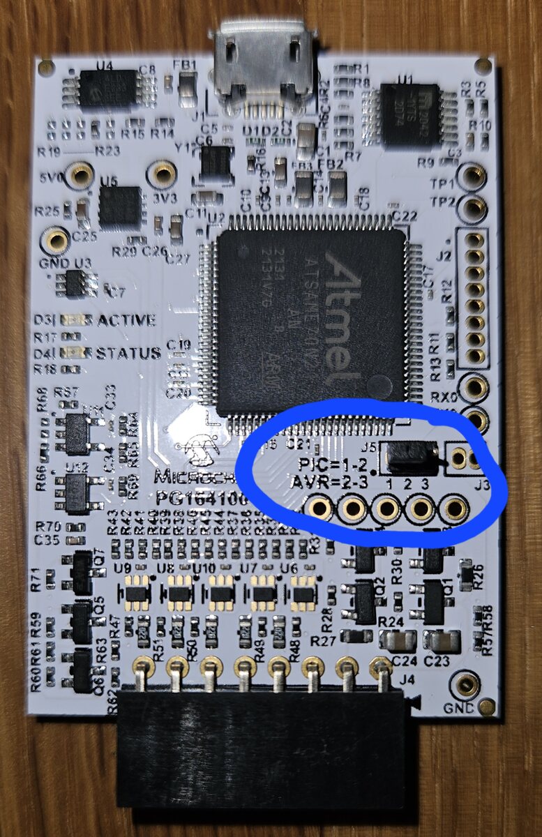
Bestückte Leiterplatte mit Atmel Mikrocontroller
U4 C8 FB1 R1 U1 R15 R14 C5 C6 D1 D2 R9 R10 R5 3V3 U5 C10 C11 C22 J2 R12 R11 R13 RX0 J3 PIC1-2 AVR=2-3 1 2 3 J3 ACTIVE STATUS C19 R18 R17 D31 R25 C25 R29 C26 U3 GND R68 R66 R60 C33 R63 R65 R64 R43 R42 R39 R38 R37 R36 R35 R34 R33 R32 R31 R30 R29 R28 R27 R26 R25 R24 R23 R22 R21 R20 R19 R16 R15 R14
in „[V] Microchip Snap (neue Version) mit Atmel Adapter“ · Markt · · Platinenfotos
-
Datei
swdisplay_nokia.h
noscreen_cache // Schattenspeicher nicht verfuegbar, Display nur im // Directwritemodus verfuegbar #include <avr/io.h> #include <avr/pgmspace.h> #include <util/delay.h> #include <stdlib.h> #include <string.h> #include <stdio.h> //------------------------------------------------------------- // Hardwareanbindung
in „Nokia 5110 LCD defekt ?“ · Mikrocontroller und Digitale Elektronik ·
-
Datei
objdump.txt
mov r3, fp 8006d64: e28d1020 add r1, sp, #32 8006d68: e8910003 ldm r1, {r0, r1} 8006d6c: fa0006c1 blx 8008878 <__aeabi_dsub> 8006d70: e58d0008 str r0, [sp, #8] 8006d74: e58d100c str r1, [sp, #12] 8006d78: e28d3008 add
in „STM32F4 HardFault Interrupt bei stdlib Funktionen“ · Mikrocontroller und Digitale Elektronik ·
-
Datei
avr_oscilloscope_1_.htm
> <TABLE cellSpacing=0 cellPadding=0 width=1000 align=center height=1000 > <TBODY><TR > <TD height=28 vAlign=top width=1277 > <P style="LINE-HEIGHT: 100%; MARGIN-TOP: 0px; MARGIN-BOTTOM: 0px" align=left><IMG border=0 src="images/avr_oscilloscope_htm_avr_osc_html_smartbutton1.gif" namo_npi=":EmbededNPI001
in „AVR-OZZI_fuses_help“ · Mikrocontroller und Digitale Elektronik ·
-
Datei
dragon-fuse.txt
--- ---- ----- ----- ---- ------ ------ ---- ------ ----- ----- --------- flash 65 6 32 0 yes 4096 64 64 4500 4500 0xff 0xff Block Poll Page Polled Memory Type Mode Delay Size Indx Paged Size Size #Pages MinW MaxW ReadBack ----------- ---- ----- ----- ---- ------ ------ ---- ------ ----- ----- ------
in „avrdude fuses aus debugwire schreiben“ · Mikrocontroller und Digitale Elektronik ·
-
Datei
IREIN.ASM
Size :149 words ;* Low Register Usage :5 ;* High Register Usage :11 ;* Interrupt Usage : ;* Based on :avr410 rc5, avr100 EEprom access, RC5Lamp ;* ;* DESCRIPTION ;* This Application switch a lamp on/off with RC5 if ;* system and lamp_nr are correct ;* system and lamp_nr are can be change with the "learn_button
in „ATTiny22 Software ändern“ · Mikrocontroller und Digitale Elektronik ·
-
PDF
MCP79521.pdf
Real-Time Clock/Calendar Device Selection Table Part Number SRAM (Bytes) EEPROM (Kbits) Unique ID MCP79510 64 1 Blank MCP79520 64 2 Blank ™ MCP79511 64 1 EUI-48 MCP79521 64 2 EUI-48™ ™ MCP79512 64 1 EUI-64 MCP79522 64 2 EUI-64™ • 128-Bit Protected EEPROM Area: Timekeeping Features • Real-Time Clock/Calendar
in „RTC -> MCP79521“ · Mikrocontroller und Digitale Elektronik ·
-
Datei
display.bas
As Integer Print #1 , "Wait for Drive" $Include "Config_MMC.bas" If Gbdriveerror = 0 Then ' Include AVR-DOS Configuration and library $Include "Config_AVR-DOS.BAS" Print #1 , "Init File System ... "; Btemp1 = Initfilesystem(1) ' Partition 1 ' use 0 for drive without Master boot record If Btemp1 <> 0 Then
in „Atmega128 + SD Card + 3.5" Display“ · Mikrocontroller und Digitale Elektronik ·
-
Datei
8080int-jmp.asm
... .equ ZFL_S = 7 .equ ZFL_Z = 6 .equ ZFL_H = 4 .equ ZFL_P = 2 .equ ZFL_N = 1 .equ ZFL_C = 0 .equ AVR_T = SREG_T .equ AVR_H = SREG_H .equ AVR_S = SREG_S .equ AVR_V = SREG_V .equ AVR_N = SREG_N .equ AVR_Z = SREG_Z .equ AVR_C = SREG_C ;------------------------------------------------; ; Load table value
in „CP/M auf ATmega88“ · Mikrocontroller und Digitale Elektronik ·
-
Datei
iom644pa.h
_AVR_IOXXX_H_ # define _AVR_IOXXX_H_ "iom644PA.h" #else # error "Attempt to include more than one <avr/ioXXX.h> file." #endif #ifndef _AVR_ATmega644PA_H_ #define _AVR_ATmega644PA_H_ 1 /* Registers and associated
in „ATMega644p USART-Interruptvector?“ · Mikrocontroller und Digitale Elektronik ·
-
Datei
avrasm.txt
ganz von vorn anfangen (bei 0 und 1 sozusagen). Als konkrete Hardware dient dabei der Mikrocontroller AVR AT90S4433 von Atmel. Für Beispiel-Schaltungen und weiterführende Texte und Beispiele wird das Tutorial auf http://www.mikrocontroller.net und das Tutorial auf http://www.avr-asm-tutorial.net empfohlen
-
Datei
enc28j60.c
#include <avr/io.h> #include "enc28j60.h" #include "spi.h" /******************************************************************************/ /** \file enc28j60.c * \brief Driver code for enc28j60. * \author Iain Derrington
in „Problem mit ENC28J60“ · Mikrocontroller und Digitale Elektronik ·
-
Datei
pegasus_5x7_font.bas
'############################################################### ' Bascom AVR Test for the Powertip PH9867C CSTN Color Display ' This demo displays a text screen with 15 x 7 characters using ' 5x7 Font. ' Display Controller Type: ST7626 ' Tested on ATMega8, 70% Flash used. Internal
in „Mini-Farbdisplay (+mehr) für 1 Euro“ · Mikrocontroller und Digitale Elektronik ·
-
Datei
8080int-jmp.asm
... .equ ZFL_S = 7 .equ ZFL_Z = 6 .equ ZFL_H = 4 .equ ZFL_P = 2 .equ ZFL_N = 1 .equ ZFL_C = 0 .equ AVR_T = SREG_T .equ AVR_H = SREG_H .equ AVR_S = SREG_S .equ AVR_V = SREG_V .equ AVR_N = SREG_N .equ AVR_Z = SREG_Z .equ AVR_C = SREG_C ;------------------------------------------------; ; Load table value
in „CP/M auf ATmega88“ · Mikrocontroller und Digitale Elektronik ·
-
Datei
8080int-jmp.asm
... .equ ZFL_S = 7 .equ ZFL_Z = 6 .equ ZFL_H = 4 .equ ZFL_P = 2 .equ ZFL_N = 1 .equ ZFL_C = 0 .equ AVR_T = SREG_T .equ AVR_H = SREG_H .equ AVR_S = SREG_S .equ AVR_V = SREG_V .equ AVR_N = SREG_N .equ AVR_Z = SREG_Z .equ AVR_C = SREG_C ;------------------------------------------------; ; Load table value
in „CP/M auf ATmega88“ · Mikrocontroller und Digitale Elektronik ·
-
Datei
Sinus.c
#include <avr/io.h> #include <avr/interrupt.h> #include <avr/pgmspace.h> #include <inttypes.h> #include <stdlib.h> #define WERTE 512 #define F_PWM 3906.25 typedef struct{ uint8_t anzahl; uint8_t teiler; uint8_t sinwerte
in „Verbesserungsideen zu PWM Sinus“ · Mikrocontroller und Digitale Elektronik ·
-
PDF
TempSensorKTY81-120.pdf
RPTC ADC Aref RPTCR 1 2) Insgesamt sollte durch den PTC nicht mehr als 1 mA fließen.U Aref,ist beim AVR 2,56 V. U R= => Rmin R1 PTC=2560Ohm I Bei -30 Grad Celsius besitzt der KTY81-100 einen minimalen Widerstand von 609 Ohm. R1=2560Ohm−609Ohm=1951Ohm R =2kOhm 1 3) Der Widerstand im Bezug zur Temperatur
in „Wieviel Strom kann ich aus Aref beziehen?“ · Mikrocontroller und Digitale Elektronik ·
-
Datei
stk500_1200.asm
e0 ldi r17, 0x01 ; 1 218: 22 27 eor r18, r18 21a: 51 0f add r21, r17 21c: 62 1f adc r22, r18 21e: 64 c0 rjmp Send_CR ; 0x2e8 ;;; Read eeprom memory byte (address is auto incremented). ;;; The byte read is sent out the serial port. ;; 'd' : Read_Eeprom_Byte: 220: 44 36 cpi r20, 0x64 ; 100 222: 71 f4
in „AVRISP => Hex-Datei vom 1200er“ · Mikrocontroller und Digitale Elektronik ·
-
PDF
ATMEGA8_DATENBLATT.pdf
AIO outputs shown in the port figure and the digital logic of the TWI module. 62 ATmega8(L) 2486X–AVR–06/10 ATmega8(L) Alternate Functions of The Port D pins with alternate functions are shown in Table 28. Port D Table 28. Port D Pins Alternate Functions Port Pin Alternate Function PD7 AIN1 (Analog
in „I2C/TWI TWBR > 10 warum?“ · Mikrocontroller und Digitale Elektronik ·
-
Datei
nano_os_OPTs.txt
delete_message) { 642: ef 92 push r14 644: ff 92 push r15 646: 0f 93 push r16 648: 1f 93 push r17 64a: cf 93 push r28 64c: df 93 push r29 64e: ec 01 movw r28, r24 650: 8b 01 movw r16, r22 652: 94 2f mov r25, r20 654: e2 2e mov r14, r18 sregsys = SREG; 656: 8f b7 in r24, 0x3f ; 63 658: 80 93 0a 01 sts
-
Datei
nano_os_2_OPTs.txt
; 0xca0 <free+0x60> c5e: 40 e0 ldi r20, 0x00 ; 0 c60: 50 e0 ldi r21, 0x00 ; 0 c62: ac 17 cp r26, r28 c64: bd 07 cpc r27, r29 c66: 08 f1 brcs .+66 ; 0xcaa <free+0x6a> c68: bb 83 std Y+3, r27 ; 0x03 c6a: aa 83 std Y+2, r26 ; 0x02 c6c: fe 01 movw r30, r28 c6e: 21 91 ld r18, Z+ c70: 31 91 ld r19, Z+ c72
-
PDF
AVR_tutorial.pdf
L I C A T I O N N O T E F O R T H E A V R F A M I L Y ;* ;* Number :AVR000 ;* File Name :"2313def.inc" ;* Title :Register/Bit Definitions for the AT90S2313 ;* Date :99.01.28 ;* Version :1.30 ;* Support E-Mail :avr@atmel.com ;* Target MCU :AT90S2313 ... Aber jetzt weiter
in „AVR-Tutorial als PDF bzw *.doc“ · Mikrocontroller und Digitale Elektronik ·
-
Datei
libsht.c
direction statement for the SCK line to sht_softreset() - made my modifications public domain */ #include <avr/io.h> //Microcontroller specific library, e.g. port definitions #include <math.h> // #include <stdlib.h> // #include <inttypes.h> // #include <util/delay.h> #include "libsht.h" #include <avr/pgmspace.h
in „SHT11 misst Mist“ · Mikrocontroller und Digitale Elektronik ·
-
Datei
avrdude_out.txt
26: no interesting data avrdude: avr_read(): skipping page 27: no interesting data avrdude: avr_read(): skipping page 28: no interesting data avrdude: avr_read(): skipping page 29: no interesting data avrdude: avr_read(): skipping page
in „avrdude braucht lange zum Beenden (Linux)“ · Mikrocontroller und Digitale Elektronik ·
-
Datei
linux-2.6.27.grasshopper.1.patch
diff -rupN atngw100//arch/avr32/boards/grasshopper/btn.c grasshopper//arch/avr32/boards/grasshopper/btn.c --- atngw100//arch/avr32/boards/grasshopper/btn.c 1970-01-01 01:00:00.000000000 +0100 +++ grasshopper//arch/avr32/boards/grasshopper
in „AVR32 grasshopper patch für ATMEL buildroot 2.2.1“ · Mikrocontroller und Digitale Elektronik ·
-
Datei
avrasm.txt
ganz von vorn anfangen (bei 0 und 1 sozusagen). Als konkrete Hardware dient dabei der Mikrocontroller AVR AT90S4433 von Atmel. Ansonsten wird als Assembler-Programm avrasm.exe von Atmel verwendet, das Teil der AVR-Studio-Software ist, die man sich bei http://www.atmel.com gratis besorgen kann. Für Beispiel-Schaltungen
-
PDF
avrasm.pdf
Hardware dient dabei der Mikrocon- mal-Zahl 255 kann man damit folgendermaßen auseinandernehmen: troller AVR AT90S4433 von Atmel. Ansonsten wird als Assembler-Programm avrasm.exe von Atmel verwendet, 2 5 5 das Teil der AVR-Studio-Software ist, die man sichhttp://www.atmel.com gratis besorgen kann. | | |_ 5
-
Datei
mv_gcctest9.lst
<avr/pgmspace.h> 18:mv_gcctest9.c **** #include <avr/io.h> 19:mv_gcctest9.c **** #include "timer.h" 20:mv_gcctest9.c **** #include "UartPrintF.h" 21:mv_gcctest9.c **** 22:mv_gcctest9.c **** int main(void) 23:mv_gcctest9.c **** { 109 .LM1: 110 /* prologue: frame size=0 */ 111 0000 C0E0 ldi r28,lo8(__stack - 0) 112 0002 D0E0 ldi r29,hi8(__stack - 0) 113 0004 DEBF out __SP_H__,r29 114 0006 CDBF out __SP_L__,r28 115 /* prologue end (size=4) */ 24:mv_gcctest9.c **** double a1=1.234, a2=2.756,
in „Multiplikation ist zu schnell...“ · Mikrocontroller und Digitale Elektronik ·
-
PDF
MyPC_sch.pdf
VS_TX 27 TX 5 AVR_RST 90 /Reset_PDI 95 PA0 CVCC1 7 PDI_DATA 89 PDI_Data ADC0_ADC1_AC1_PA1 96 PA1 33 GPIO0 CVCC2 24 ADC2_AC2_DAC0_PA2 97 PA2 34 GPIO1 CVCC3 31 ADC3_AC3_DAC1_PA3 98 PA3 9 GPIO2 ADC4_AC4_PA4 99 PA4 R26 10
in „Bitte Schaltplan&Layout checken“ · Mikrocontroller und Digitale Elektronik ·
-
PDF
LED_Matrix_Controller_V5.pdf
i.W. aus mehreren langen Schieberegistern, welche jeweils eine LED-Reihe betreibt. Für ein typisches 64x64 LED-Modul werden 6 Schieberegister mit je 64 Bit verwendet. Jeweils 3 für die oberen 32 Reihen und 3 für die unteren 32 Reihen. Jede 3er Gruppe treibt dabei jeweils die roten, grünen und blauen RGB-LEDs
in „Universeller 64x64 LED-Matrix Controller“ · Projekte & Code ·
-
Datei
TMC222_AVR.c
************************************************* Example library for using a TMC222 together with AVR processors that have a hardware TWI interface (e.g. ATmega8, ATmega48, ATmega88, ATmega168, ATmega16, ATmega32, ATmega64, ATmega128, AT90CAN128 and many more). It implements and interrupt driven TWI
in „ELV USB-I2C & Schrittmotorsteuerung iSMT“ · Mikrocontroller und Digitale Elektronik ·
-
PDF
EtherBoardSch.pdf
.9Volt= A12 25 26 A13 PE4 25 26 /NICINT 10u max. 100mA GND GND GND GND GND GND GND GND GND GND A14 27 28 A15 PE6 27 28 PE7 A /RD 29 30 /WR I2CCLK 29 30 I2CDAT A /RESET 31 32 ALE RXD1 31 32 TXD1 GND GND 33 34 PD4 33 34 PD5 PD6 35 36 PD7 GND GND PG3 37 38 PG4 Rev# Datum Rev. Obj. 39 40 E-LAB EtherBoard GND GND AVR + mega103 + RTL8019 E-LAB Copyright by E-LAB 1 E-LAB C O M P U T E R S Tel. 07268/9124-0 Datum: 4-Aug-2001 Blatt 1 von 1 D74906 Bad Rappenau Fax 07268/9124-24 Name: R. Hofmann 1 2 3 4 5 6 7 8
in „Elektronik über ein Ethernet Netzwerk steuern?“ · Mikrocontroller und Digitale Elektronik ·
-
PDF
AVR-ASM-Tutorial_16_05_08_v1.pdf
benutzen, wenn mehr Strom benötigt wird.............................................................28 4 AVR-Tutorial: Logik........................................................................................................................29 4.1Allgemeines.........................................
in „AVR-ASM-Tutorial: PDF 16.5.08“ · www.mikrocontroller.net ·
-
PDF
HausAutoTest.pdf
BLM21AG102SN1D 100nF U10 1 1 GND 18 VDDANA PD30 61 PD30 GND _ L1 17 60 PD29 5V 2 N 100nF 3 GNDANA PD29 59 PD28 N C PD28 C D GND PD27 58 CS_SCH1 GND D 5V 51 VDDIO3 57 CS_Temp1 35 VDDIO2 PD21 4.7uF 1nF 5 PD14 56 CS_RTC VDDIO1 55 CS_EEProm PD13 C4 C7 PD12 54 PD12 P2 P4 PD11 53 PD11 1 1 50 CS_SDKarte 2 2 PD03 PC10
in „AT32UC3C2 Schaltplan“ · Mikrocontroller und Digitale Elektronik ·
-
PDF
HausAutoTest.pdf
BLM21AG102SN1D 100nF U10 1 1 GND 18 VDDANA PD30 61 PD30 GND _ L1 17 60 PD29 5V 2 N 100nF 3 GNDANA PD29 59 PD28 N C PD28 C D GND PD27 58 CS_SCH1 GND D 5V 51 VDDIO3 57 CS_Temp1 35 VDDIO2 PD21 4.7uF 1nF 5 PD14 56 CS_RTC VDDIO1 55 CS_EEProm PD13 C4 C7 PD12 54 PD12 P2 P4 PD11 53 PD11 1 1 50 CS_SDKarte 2 2 PD03 PC10
in „AT32UC3C2 Schaltplan“ · Mikrocontroller und Digitale Elektronik ·
-
Datei
regler_sensor.c
/* * main.c * * Created: 11.03.2013 10:28:50 * Author: */ #include <avr/io.h> #include <util/delay.h> #include <avr/interrupt.h> #include <stdio.h> #include <stdlib.h> #include "UART.h" #include "1wire.h" #include "measure.h" #include "hardware.h
in „LCD Display funktioniert bei Zusammenstellung nicht“ · Mikrocontroller und Digitale Elektronik ·
-
Datei
Kuckuck.c
| \ === | | '---o GND | | | | | === '---------o----------' GND | === GND (created by AACircuit v1.28.6 beta 04/19/05 www.tech-chat.de) */ // Achtung! Darauf achten, dass F_CPU=8000000UL definiert ist und die FUSES entsprechend gesetzt sind. #define F_CPU 8000000UL #include <avr/io.h> #include <avr/sleep.h
in „ATTINY 433MHz Fuchssender mit akustischem Grillen-Sound“ · Projekte & Code ·
-
Datei
avr_test3.c
0x24,0x2a,0x7f,0x2a,0x12, // 24 $ the maximum number of characters per row is only 14. :) 0x23,0x13,0x08,0x64,0x62, // 25 % 0x36,0x49,0x55,0x22,0x50, // 26 & 0x00,0x05,0x03,0x00,0x00, // 27 ' 0x00,0x1c,0x22,0x41,0x00, // 28 ( 0x00,0x41,0x22,0x1c,0x00, // 29 ) 0x14,0x08,0x3e,0x08,0x14, // 2a * 0x08,0x08,0x3e,
in „Problem mit Nokia 3310 Display an ATtiny2313“ · Mikrocontroller und Digitale Elektronik ·
-
Datei
Fastboot.asm
C002 0C22 '....h........$..' rcall avr061C ; 0612 D009 0C24 '..h........$....' set ; 0613 9468 0C26 'h........$......' avr0614: bld r0, 0 ; 0614 F800 0C28 '.......$........' rcall avr0621 ; 0615 D00B 0C2A '.....$........P.' bld r1, 0 ; 0616
in „32 kHz kompatibler Bootloader gesucht“ · Mikrocontroller und Digitale Elektronik ·
-
PDF
Timer_-_AVR-AN130.pdf
0 (Timer Stopped) 0 0 1 P (System Clock) P (System Clock/Asynchronous CK CK2 Clock) 0 1 0 P CK PCK28 0 1 1 P CK4 PCK232 1 0 0 P /256 P /64 C CK2 1 0 1 P /1024 P /128 CK CK2 1 1 0 External Pin Tx falling edgP /256 CK2 1 1 1 External Pin Tx rising edgeP /1024 CK2 fCK (PCKx ⁄ PVal) PCKx TOV CK = MaxVal
in „Timererklärung“ · Mikrocontroller und Digitale Elektronik ·
-
Datei
spiusb.cpp
/* SPIUSB, Programmierer fuer AVR mit FT232R ueber USB * Mayer Bernhard, Rev. 0.2, 26. Mai. 2010 */ #include<stdio.h> #include<windows.h> #include "ftd2xx.h" FT_STATUS ftStatus; FT_HANDLE ftHandle; // bit 0 RESET - bit 1 SCK - bit 2
in „SPIUSB - AVR über GPIOs von FT232R programmieren“ · Projekte & Code ·
-
PDF
techb_myethernet_de_en.pdf
10polige ISP-Schnittstelle. www.myAVR.de © Laser & Co. Solutions GmbH – 06/2010 www.myAVR.com myEthernet Technische Beschreibung / technical description 5/48 1 Produkteigenschaften 1 Product features • 10 MegaBit Ethernet mit ENC28J60 von
in „Ulrich Radigs TCP/IP Stack auf MyAvr, ENC startet immer neu, Soft Spi Problem“ · Mikrocontroller und Digitale Elektronik ·
-
Datei
test.lst
00 jmp 0x8a 00000054 <__ctors_end>: 54: 11 24 eor r1, r1 56: 1f be out 0x3f, r1 ; 63 58: cf e5 ldi r28, 0x5F ; 95 5a: d4 e0 ldi r29, 0x04 ; 4 5c: de bf out 0x3e, r29 ; 62 5e: cd bf out 0x3d, r28 ; 61 00000060 <__do_copy_data>: 60: 10 e0 ldi r17, 0x00 ; 0 62: a0 e6 ldi r26, 0x60 ; 96 64: b0 e0 ldi r27,
in „WINAVR mag keinen Vergleich mit 1“ · Mikrocontroller und Digitale Elektronik ·