-
Datei
sd-reader_20090330_mega328.patch
select_card() PORTB &= ~(1 << PORTB2) + #define unselect_card() PORTB |= (1 << PORTB2) #elif defined(__AVR_ATmega16__) || \ defined(__AVR_ATmega32__) #define configure_pin_mosi() DDRB |= (1 << DDB5) @@ -91,8 +94,8 @@ #define configure_pin_ss() DDRB |= (1 << DDB4) #define configure_pin_miso() DDRB &= ~(1
-
Datei
nec_x.c
us #define wzsih (6000/64) // Startimpuls high 6000 us // 2250 us #define wzrl (1550/64) // Repeatimpuls low 1550 us #define wzrh (3050/64) // Repeatimpuls high 3050 us // 560 us #define wzpl (160/64) // Pause low 160 us #define wzph (960/64) // Pause high 960 us // 560 us #define wzi0l (160/64) // Impuls 0 low 160 us #define wzi0h (960/64) // Impuls 0 high 960 us // 1690 us #define wzi1l (1140/64) // Impuls 1 low 1140 us #define wzi1h (
in „IR NEC Protokoll einlesen“ · Mikrocontroller und Digitale Elektronik ·
-
Datei
avrdude.txt
heinz@pc:~$ avrdude -p m8 -c avr911 -vvvv -P /dev/ttyUSB0 -U flash:w:ledan.hex:i avrdude: Version 6.0.1, compiled on Oct 21 2013 at 15:55:32 Copyright (c) 2000-2005 Brian Dean, http://www.bdmicro.com/ Copyright (c) 2007-2009 Joerg
in „myAVR Board light welcher Programmer ist verbaut? für Linux“ · Mikrocontroller und Digitale Elektronik ·
-
Datei
ws2812test.c
ws2812test.c * * Created: 12.12.2012 00:02:22 * Author: adrock */ #define F_CPU 16000000 #include <avr/io.h> #include <util/delay.h> extern void WS_init(void); extern void WS_put(uint8_t *D, uint16_t Num); #define NUMDATA 15 static uint8_t MyData[NUMDATA] = { 1,1,1, 16,16,16, 32,32,32, 64,64,64, 128,128,128
in „Serielle Ansteuerung / Protokoll WS2812 RGB LED“ · Mikrocontroller und Digitale Elektronik ·
-
Datei
main.c
#elif (PS == 8) #define PSOR 2 #elif (PS == 32) #define PSOR 3 #elif (PS == 64) #define PSOR 4 #elif (PS == 128) #define PSOR 5 #elif (PS == 256) #define PSOR 6 #elif (PS == 1024) #define PSOR 7 #endif #define COMP (EPSILON * CPUFREQ / PS) typedef
in „Mini-Helikopter“ · Mikrocontroller und Digitale Elektronik ·
-
Datei
pal_board.c
CFG_FEATURE1_RESV7 0x80 /** Base address (in EEPROM) of configuration data record */ #define CFG_BASE_ADDRESS 64 /** Maximal length of textual board name */ #define CFG_NAMELEN (32 - sizeof(uint16_t)) /** Total space reserved for binary configuration data */ #define CFG_BINARYLEN 32 #ifdef EXTERN_EEPROM_AVAILABLE
-
Datei
Dump_SD.txt
readBlock() ok readSector(0x00000085) readBlock(17) status = 0xfe readBlock() ok BytsPerSec:512 SecPerClus:32 RsvdSecCnt:6 NumFATs:2 RootEntCnt:512 TotSec16:0 FATSz16:237 HiddSec:133 TotSec32:1939323 FATSz32:1814626432 RootClus:1095639119 RootDirSect:32 FATSz:237 TotSec :1939323 DataSec:1938811 CntOfClust:60587
in „SD Karte lässt sich nicht initialisieren“ · Mikrocontroller und Digitale Elektronik ·
-
Datei
peinpaus.c
// Atmega 8, intern 8 Mhz, Isr Timer 1 1ms #ifndef F_CPU #define F_CPU 8000000UL #endif #include <avr/io.h> #include <avr/interrupt.h> #include <stdbool.h> #include <util/delay.h> ////////////////////////////////////////////////////////////////////////// // Zeitperioden //Wartzeit_R1 abwarten, wenn
in „Pins Schieberegister zeitlich schalten“ · Mikrocontroller und Digitale Elektronik ·
-
Datei
Fading_LED.txt
******************************************* #define F_CPU 8000000L #include <inttypes.h> #include <avr/io.h> #include <util/delay.h> #include <avr/pgmspace.h> // Globale Variablen uint16_t pwmtable_10[64] PROGMEM = {0, 1, 1, 2, 2, 2, 2, 2, 3, 3, 3, 4, 4, 5, 5, 6, 6, 7, 8, 9, 10, 11, 12, 13, 15, 17, 19
in „PWM bei Mega8 und 2313“ · Mikrocontroller und Digitale Elektronik ·
-
Datei
main.c
*******************************************************************/ #include "define.h" #include <avr\io.h> #include <avr\interrupt.h> #include <stdint.h> #include <util\delay.h> #include <avr/pgmspace.h> #include <stdlib.h> #include <string.h> #include <avr\eeprom.h> #include <avr\sleep.h> #include
in „AD-Wandlung und Nutzung JTAG möglich?“ · Mikrocontroller und Digitale Elektronik ·
-
Datei
main.c
#include <avr/io.h> #include <util/delay.h> #include <avr/eeprom.h> #include <avr/interrupt.h> #include <stdint.h> #include <string.h> #include <stdio.h> #include <stdlib.h> #include <adc.h> #include <i2c.h> #include
in „arrays und struct in funktionen“ · Mikrocontroller und Digitale Elektronik ·
-
Datei
avrasm.txt
hoch 3 = 1 * 8 = 8 | | | |_________ 1 * 2 hoch 4 = 1 * 16 = 16 | | |___________ 1 * 2 hoch 5 = 1 * 32 = 32 | |_____________ 1 * 2 hoch 6 = 1 * 64 = 64 |_______________ 1 * 2 hoch 7 = 1 * 128 = 128 ----- 255 Jetzt könnte man natürlich fragen: Und wieso ist das nicht gleich 2 hoch 8, also 256 ? Antwort
-
PDF
avrasm.pdf
binary digit” ableitet. | | | |_________ 1 * 2 hoch 4 = 1 * 16 = 16 | | |___________ 1 * 2 hoch 5 = 1 * 32 = 32 | |_____________ 1 * 2 hoch 6 = 1 * 64 = 64 Die Bits eines Bytes werden von hinten nach vorn gezählt: das letzte Bit (LSB, Least Significant Bit) ist Bit Num- |_______________ 1 * 2 hoch 7 = 1 *
-
PDF
xminilab-manual.pdf
February, 2012 Page | 7 Xminilab User’s Manual 1.3 Specifications General Specifications: - ATXMEGA32A4U 36KB Flash, 4KB SRAM, 1KB EEPROM. - Graphic OLED display 2.42", 128x64 pixels. 40,000 hours minimum life time (to 50% original brightness). - Module size: 3.3" x 1.75". - PDI interface. - 4 tactile
in „USART - xmodem (Xminilab) - Bildübertragung“ · Mikrocontroller und Digitale Elektronik ·
-
PDF
xminilab-manual.pdf
February, 2012 Page | 7 Xminilab User’s Manual 1.3 Specifications General Specifications: - ATXMEGA32A4U 36KB Flash, 4KB SRAM, 1KB EEPROM. - Graphic OLED display 2.42", 128x64 pixels. 40,000 hours minimum life time (to 50% original brightness). - Module size: 3.3" x 1.75". - PDI interface. - 4 tactile
in „ATXmega32 flashen mit ATMEL Flip (Xminilab)“ · Mikrocontroller und Digitale Elektronik ·
-
Datei
ks0108.c
#include <inttypes.h> #include <avr/io.h> #include <avr/pgmspace.h> #include "ks0108.h" struct displayPos pos; void ks0108Enable(void) { volatile uint8_t i; LCD_CMD_PORT |= 0x01 << EN; // EN high level width: min. 450ns asm volatile("
in „KS0108 überlagernde Schrieftzeichen“ · Mikrocontroller und Digitale Elektronik ·
-
Datei
ks0108.c
#include <inttypes.h> #include <avr/io.h> #include <avr/pgmspace.h> #include "ks0108.h" struct displayPos pos; void ks0108Enable(void) { volatile uint8_t i; LCD_CMD_PORT |= 0x01 << EN; // EN high level width: min. 450ns asm volatile("
in „KS0108: Warum immer Anzeige auf beiden LCD-Hälften?“ · Mikrocontroller und Digitale Elektronik ·
-
Datei
ks0108.c
#include <inttypes.h> #include <avr/io.h> #include <avr/pgmspace.h> #include "ks0108.h" struct displayPos pos; void ks0108Enable(void) { volatile uint8_t i; LCD_CMD_PORT |= 0x01 << EN; // EN high level width: min. 450ns asm volatile("
in „Displaytech 64128A an ATMega8“ · Mikrocontroller und Digitale Elektronik ·
-
Datei
ks0108.c
#include <inttypes.h> #include <avr/io.h> #include <avr/pgmspace.h> #include "ks0108.h" struct displayPos pos; void ks0108Enable(void) { volatile uint8_t i; LCD_CMD_PORT |= 0x01 << EN; // EN high level width: min. 450ns asm volatile("
in „KS0108 nur schwarze PIXEL“ · Mikrocontroller und Digitale Elektronik ·
-
PDF
doc7707.pdf
0x1800 0x17FF 0x1FFF 0x0000 - 0x1000 - 0 0 4096 bytes 32 0x0FFF 0x1000 0x0FFF 0x1FFF (Page size = 64 words = 128 bytes) 239 7707F–AVR–11/10 The different BOOTSZ Fuse configurations are shown in Figure 23-2. (1) Table 23-9. Read-While-Write Limit Device Section
in „AVR (AT90USB162) - Sleep Mode und PCINT“ · Mikrocontroller und Digitale Elektronik ·
-
PDF
Atmega128_doc2467.pdf
bytes On-chip In-System Reprogrammable Flash memory for Reprogrammable program storage. Since all AVR instructions are 16 or 32 bits wide, the Flash is organized as 64K x 16. For software security, the Flash Program memory space is divided into two sections, Flash Program Boot Program section and Application
in „ATMEGA128 Timer“ · Mikrocontroller und Digitale Elektronik ·
-
 Bild
Bild
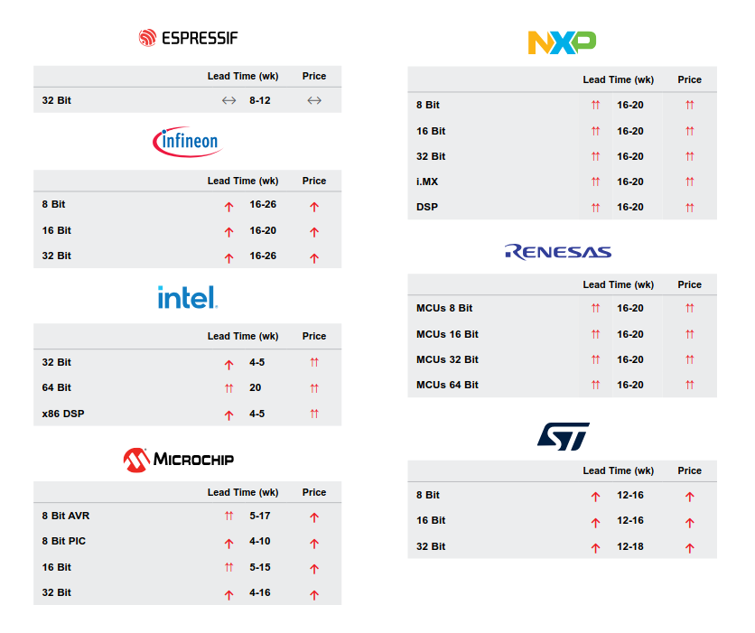
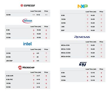
Tabelle mit Lieferzeiten und Preisen verschiedener Mikrocontroller-Hersteller
ESPRESSIF Lead Time (wk) Price 32 Bit <-> 8-12 <-> NXP 8 Bit ↑↑ 16-20 ↑↑ 16 Bit ↑↑ 16-20 ↑↑ 32 Bit ↑↑ 16-20 ↑↑ i.MX ↑↑ 16-20 ↑↑ DSP ↑↑ 16-20 ↑↑ infineon Lead Time (wk) Price 8 Bit ↑ 16-26 ↑ 16 Bit ↑↑ 16-20 ↑↑ 32 Bit ↑ 16-26 ↑ intel. Lead Time (wk) Price 32 Bit ↑ 4-5 ↑↑ 64 Bit ↑↑ 20 ↑↑ x86 DSP ↑↑ 4-5 ↑↑ RENESAS MCUs 8 Bit ↑↑ 16-20 ↑↑ MCUs 16 Bit ↑↑ 16-20 ↑↑ MCUs 32 Bit ↑↑ 16-20 ↑↑ MCUs 64 Bit ↑↑ 16-20 ↑↑ MICROCHIP Lead Time (wk) Price 8 Bit AVR ↑↑ 5-17
in „800 MHz-RP2350, Unterwasser-Sondierdrohnen, Audioforensik und Lieferzeiterhöhungen“ · Mikrocontroller und Digitale Elektronik · · Diagramme
-
Datei
mmc.c
/* * Doku, siehe http://www.mikrocontroller.net/articles/AVR_FAT32 * Neuste Version: http://www.mikrocontroller.net/svnbrowser/avr-fat32/ * Autor: Daniel R. */ #include "mmc_config.h" #include "mmc.h" #include "avr/io.h" #include "config.h" #include "avr/interrupt.h
in „MMC SD library FAT16 FAT32 read write“ · Projekte & Code ·
-
Datei
ausgabe.txt
2007-2014 Joerg Wunsch System wide configuration file is "F:\ATMEL_Daten\AVRDUDE\avrdude-6.2-mingw32\avrdude.conf" Using Port : usb Using Programmer : ehajo-isp Setting bit clk period : 50.0 avrdude: usbdev_open(): Found USBtinyISP, bus:device: bus-0:\\.\libusb0-0001--0x16d0-0x0ba5 AVR Part : ATmega8
in „Keine Verbindung zwischen uISP-Stick und Atmega-8A“ · Mikrocontroller und Digitale Elektronik ·
-
Datei
log.txt
+0x0/0x530 [<9000057c>] kernel_init+0x0/0x1b8 pdc pdc.0: Atmel Peripheral DMA Controller enabled at32_eic at32_eic.0: External Interrupt Controller at 0xfff00100, IRQ 19 at32_eic at32_eic.0: Handling 4 external IRQs, starting with IRQ 64 smc smc.0: Atmel Static Memory Controller at 0xfff03400 cpufreq: AT32AP CPU frequency driver dmac0: DesignWare DMA controller at 0xff200000 irq 2 Time: avr32 clocksource has been installed. NET: Registered protocol family 2 IP route cache hash table entries: 1024 (order
in „Grasshopper Inbetriebnahme“ · Mikrocontroller und Digitale Elektronik ·
-
Datei
VU-Meter.c
alle LEDs AUS" abgleichen * interne ADC Referenz 1.1V * Effektivwertberechnung über 1024 Samples: ca. 32ms = Intervall zum LED update * * Für die Gesamtbearbeitung reicht die Zeit mit 32 µs nicht aus, da aber die Auswertung (log) nur jedes 1024. Mal * interessiert, wird da eine AD Konvertierung verloren
in „ATTiny25: unklare Interaktion PROGMEM <-> ADC“ · Mikrocontroller und Digitale Elektronik ·
-
PDF
LCD_Controller_320x240.pdf
179 0 139 0 255 zeichnet ein 40x40 großes, schwarzes Rechteck, mit einem weißen Rand 19 160 0 120 15 64 128 zeichnet einen Kreis mit dem Mittelpunkt 160,120 und dem Radius 15, gefüllt mit der dunkelsten Graustufe und einem etwas helleren Rand 16 170 2 16 1 8 0 1 2 4 8 16 32 64 128 zeichnet ein 8x8 Pixel großes Bild mit den Daten 1, 2, 4, 8, 16, 32, 64, 128 (=schräge Linie) an die Position 16, 16 16 170 4 16 2 8 1 0 3 0 12 0 48 0 192 zeichnet ein 8x8 Pixel großes Bild (schräge Linie) an die Position 16, 16, also 3 0 12 0 48 0 192 0 genauso wie
in „Grafikfähiger LCD Controller für 320x240 LCD mit D-RAM“ · Projekte & Code ·
-
Datei
tm.patch
PWM_PIN 1 //#define PWM_DDR DDRB //#define PWM_PIN 2 -#elif defined(__AVR_ATmega164__) \ +#elif defined(__AVR_ATmega16__) \ + || defined(__AVR_ATmega32__) \ + || defined(__AVR_ATmega164__) \ || defined(__AVR_ATmega324__) \ || defined(__AVR_ATmega644__) \ || defined(__AVR_ATmega1284
-
Datei
VU-Meter.c
alle LEDs AUS" abgleichen * interne ADC Referenz 1.1V * Effektivwertberechnung über 1024 Samples: ca. 32ms = Intervall zum LED update * * Für die Gesamtbearbeitung reichte die Zeit mit 32 µs nicht aus, da aber die Auswertung (log) nur jedes 1024. Mal * interessiert, wird da eine AD Konvertierung verloren
in „VU-Meter mit Attiny13a statt LM3916“ · Projekte & Code ·
-
Datei
httpd.c
------------------------------------------------------------------*/ #include "config.h" #include <avr/io.h> #include <avr/pgmspace.h> #include <stdio.h> #include <stdlib.h> #include <string.h> #include "stack.h" #include "base64.h" #include "analog.h" #include "wol.h" #include "timer.h" #include "usart.h
in „Analogwert vergleichen“ · Mikrocontroller und Digitale Elektronik ·
-
Datei
avrasm.txt
hoch 3 = 1 * 8 = 8 | | | |_________ 1 * 2 hoch 4 = 1 * 16 = 16 | | |___________ 1 * 2 hoch 5 = 1 * 32 = 32 | |_____________ 1 * 2 hoch 6 = 1 * 64 = 64 |_______________ 1 * 2 hoch 7 = 1 * 128 = 128 ----- 255 Jetzt könnte man natürlich fragen: Und wieso ist das nicht gleich 2 hoch 8, also 256 ? Antwort
-
Datei
AFMotorcpp.txt
(__AVR_ATmega8__) || \ defined(__AVR_ATmega48__) || \ defined(__AVR_ATmega88__) || \ defined(__AVR_ATmega168__) || \ defined(__AVR_ATmega328P__) // use PWM from timer2B (pin 3) TCCR2A |= _BV(COM2B1) | _BV(
in „Arduino 2560 PWM Frequenz ändern auf 100Hz“ · Mikrocontroller und Digitale Elektronik ·
-
Datei
deinterleave2__2_.lst
main.out: file format elf32-avr Sections: Idx Name Size VMA LMA File off Algn 0 .text 0000010e 00000000 00000000 00000054 2**1 CONTENTS, ALLOC, LOAD, READONLY, CODE 1 .debug_aranges 00000020 00000000 00000000 00000162 2**0 CONTENTS
in „AVR/ATmega uint32_t Deinterleaving optimieren“ · Mikrocontroller und Digitale Elektronik ·
-
Datei
Versuch1.c
---------------------------------------------------- //#define F_CPU 3686400 // Taktfrequenz des myAVR-Boards #include <avr\io.h> // AVR Register und Konstantendefinitionen //#include <util\delay.h> // Bibliothek mit Warteroutinen //--------------------------------------------------------------------
in „Elektromotor Steuergerät“ · Mikrocontroller und Digitale Elektronik ·
-
Datei
arbitraryfunctiongenerator.c
82,85,88,91,94,97,101,103,106,109,112,115,119,122,125 }; // triangle int tr[]= { 0,2,4,6,8,10,12,14,16,18,20,22,24,26,28,30, 32,34,36,38,40,42,44,46,48,50,52,54,56,58,60,62, 64,66,68,70,72,74,76,78,80,82,84,86,88,90,92,94, 96,98,100,102,104,106,108,110,112,114,116,118,120,122,124,126, 128,130,132,134,136,138,140,142,144,146,148,150,152,154,156,158
in „Anfängerfehler (?) mit Interrupts“ · Mikrocontroller und Digitale Elektronik ·
-
Datei
Code.txt
25, 25, 25, 25, 26, 26, 26, 26, 27, 27, 27, 28, 28, 28, 28, 29, 29, 29, 30, 30, 30, 30, 31, 31, 31, 32, 32, 32, 33, 33, 33, 34, 34, 34, 35, 35, 35, 36, 36, 36, 37, 37, 38, 38, 38, 39, 39, 39, 40, 40, 41, 41, 41, 42, 42, 43, 43, 44, 44, 44, 45, 45, 46, 46, 47, 47, 48, 48, 49, 49, 50, 50, 51, 51, 52, 52
in „Port als Ausgang gesetzt geht direkt auf High. Wieso?“ · Mikrocontroller und Digitale Elektronik ·
-
Datei
Master.c
#include <avr/io.h> #include <avr/interrupt.h> //Globale Variabeln die überall, in jeder Funktion zu lesen und schreiben sind uint8_t dex =0; uint8_t hilfe=0; uint8_t ort=0; uint8_t hilfe2=0; uint8_t warte=0; uint8
in „TWI - Wie lege ich die Adresse von einem Slave fest?“ · Mikrocontroller und Digitale Elektronik ·
-
Datei
Slave.c
#include <avr/io.h> #include <avr/interrupt.h> //Globale Variabeln die überall, in jeder Funktion zu lesen und schreiben sind uint8_t dex =0; uint8_t hilfe=0; uint8_t ort=0; uint8_t hilfe2=0; uint8_t warte=0; uint8
in „TWI - Wie lege ich die Adresse von einem Slave fest?“ · Mikrocontroller und Digitale Elektronik ·
-
Datei
atue2.c
unsigned int saveb[50]; volatile unsigned int i = 0,y,r; const signed int Temp[255] = {67,67,66,66,65,65,64,64,63,63, 62,62,61,61,60,60,59,59,58,58, 57,56,55,55,54,54,53,53,52,51, 51,51,50,50,49,49,48,48,47,47, 46,46,45,44,43,43,42,42,41,41, 40,39,38,38,37,37,36,36,35,35, 34,34,33,33,32,31,31,30,30,29, 28,28,27,26,26,25,24,23,23,22
in „Array nach Interrupt auslesen“ · Mikrocontroller und Digitale Elektronik ·
-
Datei
atue2.c
unsigned int saveb[50]; volatile unsigned int y,r; const signed int Temp[255] = {67,67,66,66,65,65,64,64,63,63, 62,62,61,61,60,60,59,59,58,58, 57,56,55,55,54,54,53,53,52,51, 51,51,50,50,49,49,48,48,47,47, 46,46,45,44,43,43,42,42,41,41, 40,39,38,38,37,37,36,36,35,35, 34,34,33,33,32,31,31,30,30,29, 28,28,27,26,26,25,24,23,23,22
in „Array nach Interrupt auslesen“ · Mikrocontroller und Digitale Elektronik ·
-
PDF
diamex-avr-isp2.pdf
10-poligen Programmieranschlusses unbeschaltet ist, muss Schalter 2 auf ON ste- hen. Seite 1 DIAMEX AVR-ISP V03/16 USB-Programmieradapter für AVR-Controller LEUCHTDIODEN LED Grün Leuchtet konstant, wenn eine USB-Verbindung zum PC besteht. LED Rot Flackert beim Programmieren von AVR-Controllern. AVR-CONTROLLERVERBINDEN
in „DIAMEX USB ISP-Programmer für Atmel AVR“ · Mikrocontroller und Digitale Elektronik ·
-
PDF
diamex-avr-isp2.pdf
10-poligen Programmieranschlusses unbeschaltet ist, muss Schalter 2 auf ON ste- hen. Seite 1 DIAMEX AVR-ISP V03/16 USB-Programmieradapter für AVR-Controller LEUCHTDIODEN LED Grün Leuchtet konstant, wenn eine USB-Verbindung zum PC besteht. LED Rot Flackert beim Programmieren von AVR-Controllern. AVR-CONTROLLERVERBINDEN
in „AVR Studio 4.19“ · Mikrocontroller und Digitale Elektronik ·
-
PDF
Reflow.pdf
1 8M XTAL/S Q1 1 10k G05R RN1 4 10k R-EU_M1206 R11, R15, R21, R27 1 10k RESEU-10 R1 1 10k TRIM_EU-B64Y R5 1 10uH L-EU0207/10 L1 2 22p C2,5-3 C4, C5 2 47k R-EU_M1206 R20, R32 2 56k R-EU_M1206 R12, R22 2 82k R-EU_M1206 R13, R25 1 100 RESEU-10 R6 8 100n C2,5-3 C2, C3, C6, C7, C8, C9, C11, C13 2 220nF C2,5-3 C10, C12 1 220uF/35V ELC-5L C1 2 470k R-EU_M1206 R16, R28 2 560 RESEU-10 R3, R4 1 ATMEGA32-PU MEGA32-P IC1 1 AVR-ISP-6 AVR-ISP-6 J1 1 AVR-ISP-10 AVR-ISP-10 J2 1 B80C1500 RB1A B1 3 BC557 BC557 T1, T2, T3 1 DTS63N 40-XXDTS63N S1 1 F/TMB F/TMB SG1 3 LED3mm LED3MM LED1, LED2, LED3 1 LM336Z LM336Z
in „Reflow - Pizza Ofen“ · Platinen ·
-
PDF
Reflow.pdf
1 8M XTAL/S Q1 1 10k G05R RN1 4 10k R-EU_M1206 R11, R15, R21, R27 1 10k RESEU-10 R1 1 10k TRIM_EU-B64Y R5 1 10uH L-EU0207/10 L1 2 22p C2,5-3 C4, C5 2 47k R-EU_M1206 R20, R32 2 56k R-EU_M1206 R12, R22 2 82k R-EU_M1206 R13, R25 1 100 RESEU-10 R6 8 100n C2,5-3 C2, C3, C6, C7, C8, C9, C11, C13 2 220nF C2,5-3 C10, C12 1 220uF/35V ELC-5L C1 2 470k R-EU_M1206 R16, R28 2 560 RESEU-10 R3, R4 1 ATMEGA32-PU MEGA32-P IC1 1 AVR-ISP-6 AVR-ISP-6 J1 1 AVR-ISP-10 AVR-ISP-10 J2 1 B80C1500 RB1A B1 3 BC557 BC557 T1, T2, T3 1 DTS63N 40-XXDTS63N S1 1 F/TMB F/TMB SG1 3 LED3mm LED3MM LED1, LED2, LED3 1 LM336Z LM336Z
in „Reflow - Lötofen T962 , T962a und Elektor neu“ · Platinen ·
-
PDF
Reflow.pdf
1 8M XTAL/S Q1 1 10k G05R RN1 4 10k R-EU_M1206 R11, R15, R21, R27 1 10k RESEU-10 R1 1 10k TRIM_EU-B64Y R5 1 10uH L-EU0207/10 L1 2 22p C2,5-3 C4, C5 2 47k R-EU_M1206 R20, R32 2 56k R-EU_M1206 R12, R22 2 82k R-EU_M1206 R13, R25 1 100 RESEU-10 R6 8 100n C2,5-3 C2, C3, C6, C7, C8, C9, C11, C13 2 220nF C2,5-3 C10, C12 1 220uF/35V ELC-5L C1 2 470k R-EU_M1206 R16, R28 2 560 RESEU-10 R3, R4 1 ATMEGA32-PU MEGA32-P IC1 1 AVR-ISP-6 AVR-ISP-6 J1 1 AVR-ISP-10 AVR-ISP-10 J2 1 B80C1500 RB1A B1 3 BC557 BC557 T1, T2, T3 1 DTS63N 40-XXDTS63N S1 1 F/TMB F/TMB SG1 3 LED3mm LED3MM LED1, LED2, LED3 1 LM336Z LM336Z
in „Was haltet ihr hier von diesem Reflow-Ofen?“ · Platinen ·
-
PDF
atmega2560_2561.pdf
All three memory spaces are linear and regular. In-System The ATmega640/1280/1281/2560/2561 contains 64K/128K/256K bytes On-chip In-Sys- Reprogrammable Flash tem Reprogrammable Flash memory for program storage, see Table 3 on page 19. Since all AVR instructions are 16 or 32 bits wide, the Flash is organized
in „Ethernet Buchse“ · Mikrocontroller und Digitale Elektronik ·
-
PDF
AVRUC3_SF_GettingStarted.pdf
AVR32015: AVR32 Studio getting started Features 32-bit • Installing AVR32 Studio • Upgrading from AVR32 Studio 1.0 to 2.x Microcontrollers • Creating a AVR32 standalone application • Using examples from
in „Absturz des Controller!?“ · Mikrocontroller und Digitale Elektronik ·
-
Datei
Funzt_nicht.txt
>>>: avrdude -u -c avr910 -P COM2 -p m8 Detected 1e950f = ATmega328P ampel_neu.hex: 7.808 / 65.536 Bytes (11,91%) >>>: avrdude -u -c avr910 -P COM2 -p m8 Detected 1e950f = ATmega328P ampel_neu.hex: 7.808 / 32.768 Bytes (23,83%) ~ ~ ~ ~ ~ ~ ~ ~ ~ ~ ~ ~ ~ ~ ~ ~ >>>: avrdude -u -c avr910 -p m328p -P COM2 -U flash:w:"D:\cyg_test\GDI_C_CYGWIN\AUFGABEN\aufgabe_4\ampel_neu\default\ampel_neu.hex":a Found programmer: Id = "AVR ISP"; type = S Software Version = 2.5; Hardware Version = 2.0
in „Probleme mit AVRDUDESS 2.13“ · Mikrocontroller und Digitale Elektronik ·
-
Datei
avrdude-fuse-probl.txt
------ ---- ------ ----- ----- --------- eeprom 65 5 4 0 no 64 4 0 4000 4000 0xff 0xff flash 65 6 32 0 yes 1024 32 32 4500 4500 0xff 0xff signature 0 0 0 0 no 3 0 0 0 0 0x00 0x00 lock 0 0 0 0 no 1 0 0 4500 4500 0x00 0x00 calibration 0 0 0 0 no 2 0 0 0 0 0x00 0x00
in „Probleme mit AVRDude“ · Mikrocontroller und Digitale Elektronik ·
-
Datei
8515FZM1.asm
LED (mit R) gegen Vcc, die zwar ;auch bei einem Signal vom Master-Zündpult leuchtet, aber auch vom AVR ;angesteuert wird (multiplex zur Eingangsabfrage) und als blinkende ;Bereitschaftsanzeige für aktiven AVR und gelöschten Schusszähler dient ;(das Blinken beweist den korrekten Programmablauf). ;Der
in „Timer1: Compare-mode spinnt“ · Mikrocontroller und Digitale Elektronik ·