-
 Bild
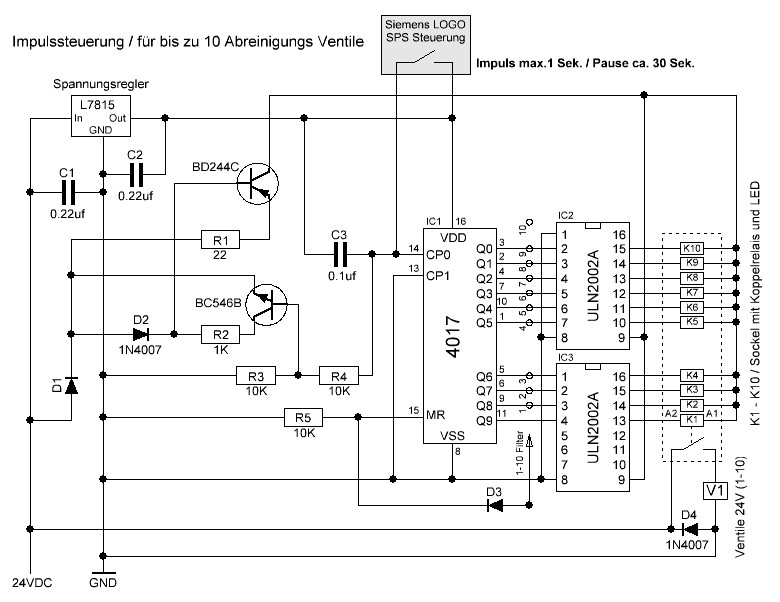
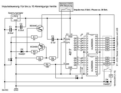
Schaltplan Impulssteuerung für Reinigungsventile
Steuerung Impuls max.1 Sek. / Pause ca. 30 Sek. Spannungsregler L7815 In Out GND C2 0.22uf C1 0.22uf BD244C R1 22 BC546B C3 0.1uf IC1 4017 VDD CP0 Q0 CP1 Q1 Q2 Q3 Q4 Q5 Q6 Q7 Q8 Q9 MR VSS 1-10 Filter IC2 ULN2002A 16 15 14 13 12 11 10 9 K10 K9 K8 K7 K6 K5 Sockel mit Koppelrelais und LED IC3 ULN2002A 16 15 14 13 12 11 10 9 K4 K3 K2 K1 Ventile 24V (1-10) D1 1N4007 D2 R2 1K R3 10K R4 10K R5 10K D3 D4 1N4007 24VDC GND
in „Impuls Steuerung mit dem CD4017B“ · Analoge Elektronik und Schaltungstechnik · · Schaltpläne
-
PDF
20110806094947526.pdf
.................................................................................................. 24 4.3. GPT3.0〞A PPLICATION C IRCUIT .......................................................................................................................................................... 25 INITIALC
in „Handydummy (Attrappe)mit richtigem Display - Sony Ericsson Vivaz“ · Mikrocontroller und Digitale Elektronik ·
-
Datei
18F4550.h
0x000000 #define CCP_SHUTDOWN_AC_H 0x040000 #define CCP_SHUTDOWN_AC_F 0x080000 #define CCP_SHUTDOWN_BD_L 0x000000 #define CCP_SHUTDOWN_BD_H 0x010000 #define CCP_SHUTDOWN_BD_F 0x020000 #define CCP_SHUTDOWN_RESTART 0x80000000 #word CCP_2 = getenv("SFR:CCPR2L") #byte CCP_2_LOW = getenv("SFR:CCPR2L") #byte
in „Unknown keyword in #FUSES "INTRC"“ · Mikrocontroller und Digitale Elektronik ·
-
Datei
Fallzahlen_DE_RKI.txt
478220a4c454480e823b17327b2bf1d4 # https://www.spiegel.de/wissenschaft/coronavirus-wie-belastbar-sind-die-rki-daten-a-13bd06d7-22a1-4b3d-af23-ff43e5e8abd6 1 24.2.2020 16 2 25.2.2020 18 3 26.2.2020 21 4 27.2.2020 26 5 28.2.2020 53 6 29.2.2020 66 7 1.3.2020 117 8 2.3.2020 150 9 3.3.2020 188 10 4.3.2020 240 11 5.3.2020 400
in „Epidemiologischer Verlauf und Analyse von Krankheiten Teil 3“ · Offtopic ·
-
PDF
8019AS.pdf
Defined Registers 16 5.2. Group 2: Plug and Play (PnP) Registers 23 5.2.1. Card Control Registers 24 5.2.2. Logical Device Control Registers 25 5.2.3. Logical Device Configuration Registers 25 6. FUNCTIONAL DESCRIPTIONS 6.1. RTL8019AS Configuration Modes 27 6.2. Plug and Play 29 6.2.1. Initiation Key
in „Webserver mit ISA Netzwerkkarte“ · Mikrocontroller und Digitale Elektronik ·
-
Datei
Fallzahlen_DE_RKI.txt
478220a4c454480e823b17327b2bf1d4 # https://www.spiegel.de/wissenschaft/coronavirus-wie-belastbar-sind-die-rki-daten-a-13bd06d7-22a1-4b3d-af23-ff43e5e8abd6 1 24.2.2020 16 2 25.2.2020 18 3 26.2.2020 21 4 27.2.2020 26 5 28.2.2020 53 6 29.2.2020 66 7 1.3.2020 117 8 2.3.2020 150 9 3.3.2020 188 10 4.3.2020 240 11 5.3.2020 400
in „Epidemiologischer Verlauf und Analyse von Krankheiten Teil 3“ · Offtopic ·
-
Datei
nibble_data.vhd
(reg24_1); -- den 24Bit wert aus reg24 ins Array(adresse) schreiben -- memory(counter1+1) <=unsigned(reg24_2); -- den 24Bit wert aus reg24 ins Array(adresse) schreiben -- memory(counter1+2) <=unsigned(reg24_3);--std_logic_vector(reg24_3(23 downto 0)); -- den 24Bit wert aus reg24 ins Array(adresse) schreiben -- memory(counter1+3) <=unsigned(reg24_4);--std_logic_vector(reg24_4(23 downto 0)); -- den 24Bit wert aus reg24 ins Array(adresse
-
PDF
AN98030.pdf
MHz (22 H) and a leakage reactance of 50 at 30 MHz (265 nH). 3.3 The bias unit The circuit uses a BD433 as the temperature sensor and a BD203 emitter follower. The unit can supply a maximum bias current of 800 mA, dependent on the value of resistor in the collector of the BD203. The bias unit should
in „Stackpole Ferrit Kerne für RF Verstärker“ · HF, Funk und Felder ·
-
PDF
ENG_DS_RT1_Inrush_0312.pdf
3.5 2.8 62 403 Tracking index of relay base PTI 250V A06 6 4.2 3.3 90 400 A12 12 8.4 6.6 360 400 A24 24 16.8 13.2 1440 400 Other Data bistable, 2 coils Material compliance: EU RoHS/ELV, China RoHS, REACH, Halogen content F05 5 3.5 2.8 42 595 refer to the Product Compliance Support Center at F06 6 4.2
in „Ersatz für Relais 5VDC / 230VAC 16A gesucht (Kühlschrankthermostat)“ · Analoge Elektronik und Schaltungstechnik ·
-
Datei
wave.asm
$18,$10,$09,$04,$01,$00 .db $01,$03,$08,$0E,$16,$20,$2B,$37 .db $45,$53,$62,$71,$81,$91,$A0,$AF .db $BD,$CA,$D6,$E1,$EB,$F2,$F8,$FC .db $FF,$FF,$FD,$FA,$F4,$ED,$E5,$DA .db $CF,$C2,$B4,$A5,$96,$87,$77,$67 .db $58,$4A,$3C,$2F,$24,$19,$11,$0A .db $05,$01,$00,$01,$03,$07,$0D,$15 .db $1F,$2A,$36,$43,$52,$60
in „Sprachausgabe mit AVR“ · Mikrocontroller und Digitale Elektronik ·
-
Datei
oe2chl.txt
56 04 75 55 01 b1 d9 e5 6a b4 13 00 40 05 |.uV.uU....j...@.| 00004370 75 6a 00 80 f4 04 75 f0 0d a4 24 2e c5 f0 34 94 |uj....u...$...4.| 00004380 c5 f0 c1 2c 12 5b 32 c2 07 c2 06 75 51 02 d1 1c |...,.[2....uQ...| 00004390 6a 20 31 4b 91 7c 01 03 bd 00 02 81 71 1d 80 08 |j 1K.|......q...| 000043a0 0d bd
in „LED Laufschrift Software“ · Mikrocontroller und Digitale Elektronik ·
-
Datei
boot.asm
lda X0080 sbc X0092 sta X0080 lda X0081 sbc X0093 sta X0081 jmp L6CB1 ; L6BCD: stz X0054 rmb X0002 L6BD1: bbr 5,X0054,L6BD1 lda #$03 sta X0050 L6BD8: bbr 6,X0054,L6BD8 lda X0135 sta X0050 lda X0050 L6BE2: bbr 6,X0054,L6BE2 lda X0134 sta X0050 lda X0050 L6BEC: bbr 6,X0054,L6BEC lda X0133 sta X0050 lda X0050
in „Mini-Farbdisplay (+mehr) für 1 Euro“ · Mikrocontroller und Digitale Elektronik ·
-
Datei
Disassembly.txt
LDI R24,0x02 Load immediate 00000034 OUT 0x24,R24 Out to I/O location 42: TCCR0B |= (1<<CS01); /* Set prescaler to 8 */ 00000035 IN R24,0x25 In from I/O location 00000036 ORI R24,0x02 Logical OR with immediate
in „Atmega88P, Blinklicht in AtmelStudio 7 simulieren“ · Mikrocontroller und Digitale Elektronik ·
-
PDF
tas5630.pdf
M1 CONFIGURATION 0 0 0 Differential 2 × BTL AD mode 0 0 1 — — Reserved 0 1 0 Differential 2 × BTL BD mode Differential Single 0 1 1 Ended 1 × BTL +2 ×SE BD mode, BTL Differential 1 0 0 Single Ended 4 × SE AD mode INPUT_C (1) INPUT_D (1) 1 0 1 Differential 1 × PBTL 0 0 AD mode 1 0 BD mode 1 1 0 Reserved
in „Ringkerntrafo 50V“ · Analoge Elektronik und Schaltungstechnik ·
-
Datei
chac.zel.htm
EC# |21 F3D2 3D/ E/ F3 G/ A/ B3 FD |22 E3C#4 B A3C^4 G A3 F#C |23 G3b^4 F E3b&4 D/ C#/ D3 EDg# |24 F3D4a G E4D3a4 C#/ b^/ C#3 ga@ TR4 [TR1 @@6] |25 ~f8d4g8a4d8g4d8a4f8e4g8a4f8b4@g8a4@ tempo 24=75 TR3 |25 volume=100 nylonStringGuitar TGG12 |25 f2d ~F2EDC#D |26 g2d a b c#2 b2 a2 g2 |27 f2d g a b2@ d2
in „zel, der Midi-Compiler, ist nach 10 Jahren wieder auferstanden“ · Offtopic ·
-
Datei
Q_mul_dissasembly.txt
V0, A1 9D009C0C 00001012 MFLO V0 9D009C10 00001810 MFHI V1 9D009C14 00C31821 ADDU V1, A2, V1 9D009C24 8C860008 LW A2, 8(A0) 9D009C28 00063FC3 SRA A3, A2, 31 9D009C2C 8C820010 LW V0, 16(A0) 9D009C30 00022FC3 SRA A1, V0, 31 9D009C34 00A60018 MULT 0, A1, A2 9D009C38 70E20000 MADD 0, A3, V0 9D009C3C 00002812
in „PIC32MX370 - Multiplikation“ · Mikrocontroller und Digitale Elektronik ·
-
Datei
MountingHole_MW_0.8x7.0mm.kicad_mod.txt
unlocked) (layer "F.Fab") (effects (font (size 1 1) (thickness 0.15))) (tstamp 781210cf-20a8-4ef7-bd94-52f49e67f56b) ) (fp_text user "${REFERENCE}" (at 0 2.5 unlocked) (layer "F.Fab") (effects (font (size 1 1) (thickness 0.15))) (tstamp 4d95b867-cd24-42a8-a2bb-610194b8b1a9) ) (fp_line (start -4.699
in „KiCad - Langloch als PAD für einen Blechstreifen - Akku Befestigung“ · Platinen ·
-
PDF
RIM_VMOS1000-V2_SPlan.pdf
15V R36 R 2 Flammschutz 4k23 LED1 1 470R D4 +15V R64 1N4148 +15V 3 2 C30 10R T1 R 8 1n B 8 C14 R41 BD139 B 2 1 180pF 63V C10 D 4 R37 6 + 680p K 1 K R42 1 D C31 3 R 1k D P K R 1 R43 Z 22u/63V R10 , R11 3 9 96 R44 D D T5 1k 0,4W 2k 0,4W Z C 8 3 W 3 W C8 6 B 7 1 R38 4 5 3 5 R 2 3 0,47 100V 20% 7 T2 T3 D
in „Radio RIM VMOS Turbo 1000B“ · Analoge Elektronik und Schaltungstechnik ·
-
Datei
1_testv24.lst
0001 0000 ; V24 Test 0002 0000 ; Daten von v24 in Buffer ab 9000 legen 0003 0000 ; 0004 0000 ; Stand 15.01.2015 nur 255 Byte empfangen 0005 0000 ; 0006 0000 ;---------------------------------------------------------
in „Suche MOPPEL Projekt in Heft oder .PDF“ · Mikrocontroller und Digitale Elektronik ·
-
PDF
FORMELNHB9.pdf
. . . . . . .31 23 Gerätetechnik 32 23.1 Empfindlichkeit . . . . . . . . . . . . . . . . . .32 . . 24 EMV und Sicherheit 33 24.1 Windlast . . . . . . . . . . . . . . . . . . . . .33 . . 24.2 Biegemoment . . . . . . . . . . . . . . . . . . . 33. 24.3 Sicherheitsabstand . . . . . . . . . . . . . . . .33
-
Datei
main.c
define G0 5 #define G1 6 #define G2 7 #define BIAS 0 #define REFO 1 #define DF 2 #define UB 3 #define BD 4 #define MSB 5 #define SDL 6 #define DRDY 7 #define A0 0 #define A1 1 #define A2 2 #define A3 3 #define MB0 5 #define MB1 6 #define R 1 #define W 0 #define ACTIVE 1 #define IDLE 0 #define DOR2 1 #define
in „Hardware SPI vs. BIT BANGING AD Wandler“ · Mikrocontroller und Digitale Elektronik ·
-
PDF
Bleigel-Akkulader.pdf
Einsatz, weil fast der gesamte Lade- 2 GND strom durch den Basis-Emitter-Über- gang fließen kann (der BD711 ist in 1: INPUT dieser Beziehung bis zu 3 A spezifi- 2: LIMITING ziert). Und wenn ein Strom durch T1 3: GND 5: OUTPUTNCE IC1 2 fließt, so leuchtet auch LED D2. Der 1 3 5 CS (kleine) Strom durch R3
in „Bleigel-Akkulader aus Elektor auf 24 Volt umstellen ?“ · Analoge Elektronik und Schaltungstechnik ·
-
Datei
dcf8.txt
00 00 00 00 00 00 40 88 d0 90 90 10 2f 81 0c 85 42 14 00 44 68 48 48 08 17 c0 86 42 a1 00 01 a2 34 24 24 04 0b e0 43 21 51 20 11 d1 1a 12 12 02 05 f0 21 90 a8 03 00 d1 1a 12 12 02 05 f0 21 90 a8 3f 68 8d 09 09 01 02 f8 10 c8 54 00 00 34 46 84 84 80 81 7c 08 64 2a b8 00 1a 23 42 42 40 40 be 04 32 15 6a
in „Was ist aus dem Thread der MeteoData geworden?“ · Mikrocontroller und Digitale Elektronik ·
-
PDF
IP_Protocol_AVR-Xx100.pdf
Resolution to 720p VSSC72P<CR> <- ○ ○ ○ ○ ○ - SC10P Set Resolution to 1080p VSSC10P<CR> <- ○ ○ ○ ○ ○ - SC10P24 Set Resolution to 1080p:24Hz VSSC10P24<CR> <- ○ ○ ○ ○ ○ - SC4K Set Resolution to 4K VSSC4K<CR> <- ○ ○ ○ ○ ○ - SC4KF Set Resolution to 4K(60/50) VSSC4KF<CR> <- - - ○ ○ ○ ○ ○ ○ ○ ○ ○ - SCAUTO Set Resolution
in „Mit Raspberry über TCP/IP auf AV-Receiver zugreifen und auf Events reagieren“ · Softwareentwicklung ·
-
Datei
schedule.lst
r27, r27 18e: 4a 95 dec r20 190: e1 f7 brne .-8 ; 0x18a <schedule+0x2e> 192: ac 1b sub r26, r28 194: bd 0b sbc r27, r29 196: a0 50 subi r26, 0x00 ; 0 198: bf 4f sbci r27, 0xFF ; 255 19a: 8c 91 ld r24, X 19c: 80 93 d4 01 sts 0x01D4, r24 t_delay = t_ctrl_lst[t_first].delta; // next delay delta 1a0: 90 e0
in „Umgang mit globalen Datenstrukturen“ · Mikrocontroller und Digitale Elektronik ·
-
Datei
bootloader.asm
$0BC8 $37 clr 0,SP ;$0BC9 $69 $80 movb L04AC,L049D ;$0BCB $18 $0C $04 $AC $04 $9D movb L04AD,L049E ;$0BD1 $18 $0C $04 $AD $04 $9E ldd L049D ;$0BD7 $FC $04 $9D cpd #$F191 ;$0BDA $8C $F1 $91 bne L0BEA ;$0BDD $26 $0B ldd L04B7 ;$0BDF $FC $04 $B7 cpd #$001B ;$0BE2 $8C $00 $1B bne L0C27 ;$0BE5 $26 $40 ldd L049D
in „HCS12 CPU Disassembler“ · Mikrocontroller und Digitale Elektronik ·
-
Datei
crc16.c
0x1231, 0x0210, 0x3273, 0x2252, 0x52b5, 0x4294, 0x72f7, 0x62d6, 0x9339, 0x8318, 0xb37b, 0xa35a, 0xd3bd, 0xc39c, 0xf3ff, 0xe3de, 0x2462, 0x3443, 0x0420, 0x1401, 0x64e6, 0x74c7, 0x44a4, 0x5485, 0xa56a, 0xb54b, 0x8528, 0x9509, 0xe5ee, 0xf5cf, 0xc5ac, 0xd58d, 0x3653, 0x2672, 0x1611, 0x0630, 0x76d7, 0x66f6
in „Floppy MFM Decoder selber bauen AVR ATmega Assembler Beispiele FDD Diskette“ · Projekte & Code ·
-
PDF
A700000007782502.pdf
-6 RT33LA12 12VDC 2-1393240-7 RT33LA24 24VDC 3-1415379-1 RT33LF05 Bistable 2 coils5VDC 4-1419136-1 RT33LF12 12VDC 2-1393240-8 RT33LF24 24VDC 2-1393240-9 RTD1L005 16A, 1 form C (CO) Monostable 5VDC 1-1415537-7 RTD1L012 pinning 5mm contact 12VDC 5-1393238-6 RTD1L024 wash tight 24VDC 8-1415398-1 RTD1LA05 Bistable 1 coil5VDC 6-1415544-4 RTD1LA24 24VDC 4-1415541-5 RTD3L012 1 form A (NO) Monostable 12VDC 5-1415393-1 RTD3L024 contact 24VDC 4-1415538-9 4 11-2019, Rev. 1119 Datasheets
in „Kontaktwiderstand der Relaiskontakte bei Minirelais“ · Mechanik, Gehäuse, Werkzeug ·
-
Datei
zeug.c
0x00,0x00,0x03,0x3F,0xF8,0x89,0x4B,0x00,0x84,0x60,0x48,0x8C,0x20,0x86,0x0A,0x88, 0x0C,0x8C,0x8E,0x1E,0xBC,0xA5,0xBD,0x3E,0xAE,0x2C,0x1C,0x1D,0x4D,0xCD,0xDB,0xFB, 0xAA,0xAA,0xAA,0x6D,0x6D,0xD9,0xD8,0xE9,0xF9,0xF9,0xB9,0xBD,0xBD,0xBD,0xBD,0xDC, 0xBC,0xBD,0xBD,0xFD,0xED,0xEF,0xCF,0xFF,0xEF,0xBF,0xFF,0xFF,0xFF,0xDF,0xFF,0xFF, 0xFD,0xEF,0xBE,0xFD,0xFD,0xDE,0xEC,0xE9,0x9F,0xFF,0x97,0x9F,0xFE,0xDF,0x9E,0xFE, 0x9E,0xBD,0xBD,0xFF,0xEF,0xDD,0xDF,0xDF,0xDE,0xFE,0x9F,0xBD,0xBE,0xFF,0xFF,0xFF, 0xBF,0xFF,0xFF,0xFF,0xFF,0xFF,0xFF,0xBD,0xFF,0xFF,0xBE,0xFF,0xFF,0xFF,0xFE,0xFE, 0xFC,0xF8,0xF8,0xF8,0xF8,0xF0,0x70,0x60,0x60,0xC0,0xC0,0x80,0x80,0x80,0x80,0x80
in „Benörige Hilfe bei Grafikdisplay LM240120“ · Mikrocontroller und Digitale Elektronik ·
-
Datei
main.c
0x00,0x00,0x03,0x3F,0xF8,0x89,0x4B,0x00,0x84,0x60,0x48,0x8C,0x20,0x86,0x0A,0x88, 0x0C,0x8C,0x8E,0x1E,0xBC,0xA5,0xBD,0x3E,0xAE,0x2C,0x1C,0x1D,0x4D,0xCD,0xDB,0xFB, 0xAA,0xAA,0xAA,0x6D,0x6D,0xD9,0xD8,0xE9,0xF9,0xF9,0xB9,0xBD,0xBD,0xBD,0xBD,0xDC, 0xBC,0xBD,0xBD,0xFD,0xED,0xEF,0xCF,0xFF,0xEF,0xBF,0xFF,0xFF,0xFF,0xDF,0xFF,0xFF, 0xFD,0xEF,0xBE,0xFD,0xFD,0xDE,0xEC,0xE9,0x9F,0xFF,0x97,0x9F,0xFE,0xDF,0x9E,0xFE, 0x9E,0xBD,0xBD,0xFF,0xEF,0xDD,0xDF,0xDF,0xDE,0xFE,0x9F,0xBD,0xBE,0xFF,0xFF,0xFF, 0xBF,0xFF,0xFF,0xFF,0xFF,0xFF,0xFF,0xBD,0xFF,0xFF,0xBE,0xFF,0xFF,0xFF,0xFE,0xFE, 0xFC,0xF8,0xF8,0xF8,0xF8,0xF0,0x70,0x60,0x60,0xC0,0xC0,0x80,0x80,0x80,0x80,0x80
in „Benörige Hilfe bei Grafikdisplay LM240120“ · Mikrocontroller und Digitale Elektronik ·
-
PDF
ECW1J-64182.pdf
-GC0024 ECW0J-B36-BD0009 ECW0D-B36-CC0006 ECW0J-B32-CE0009 ECW0J-B24-CE0006 ECW1D-C24-CC0024 ECW1D-B16-EC0024 ECL0D-B32-EC0006 ECW0D-C28-EC0006 ECW1D-C24-EC0024 ECW1J-R24-CC0024 ECW0J-B32-BC0006 ECW0D-B24-AE0024 ECW0D-C24-BE0024 ECW0D-B24-BC0006 ECL1D-B24-BC0024 ECW0D-B28-BC0006 ECW1D-B24-BC0024 ECW1J-R24-EC0024 ECW0J-J24-BC0006 ECW1J-R29-EC0024 ECW0J-R24-EC0006 ECW0D-B24-EC0006 ECW0J-B24-AE0024 ECW0J-B24-AE0006 ECT1J-R24-GC0024 ECW1D-B24
-
Datei
webasm27154_lst.txt
MOV 21H,#00H 140: 00E2 75 22 12 MOV 22H,#12H;ÖÃ×ßʱ³õÖµ 141: 00E5 75 23 00 MOV 23H,#00H 142: 00E8 75 24 00 MOV 24H,#00H 143: 00EB 75 25 03 MOV 25H,#03H 144: 00EE 75 3A 06 MOV 3AH,#06H;ÖÃÄÖʱ³õÖµ 145: 00F1 75 3B 01 MOV 3BH,#01H 146: 00F4 75 89 11 MOV TMOD,#11H 147: 00F7 75 8C 3C MOV TH0,#3CH 148: 00FA 75
in „Uhrzenbausatz mit At89C2051 funktioniert nicht“ · Mikrocontroller und Digitale Elektronik ·
-
PDF
TMC262_datasheet.pdf
rating 2.09 2013-JUL-30 SD System clock information updated. 2.09a 2013-OKT-31 BD Updated MOSFET list and blue box, corrected table width for chapter 6.6 2.10 2013-NOV-29 BD Added hint not to leave CLK input floating (blue box), added external clock transition time parameter. 2.11 2014-MAY-12 SD Updated MOSFET list. 2.12 2015-JAN-13 BD Update to MOSFET list, rename some VM to VS, update chapter 16.3 and 16.1. 2.13 2015-OCT-27 BD Update MOSFET list 24 References [TMC260] TMC260/261 Datasheet [TMC261] TMC260/261 Datasheet [TMC2660] TMC2660
in „Wärmeentwicklung Mosfet“ · Mikrocontroller und Digitale Elektronik ·
-
PDF
samsung_bn44-00264c.pdf
5 4 3 2 1 DP801 PFC BLOCK ! BD801S 1N5406 FS801 ~ + BP804 Jumper PFC OUT 2 1 ! ! ! 1KV 220pF(R) CP817 BP805 Jumper T3.15AH 250V A ! C N C 0 4 2 BP801 BAS3550TO . R 8 C 8 0 M 8 1 3 V LP801 BP802 BAS3550TO R 7 RP832 OVP u EER3120 RP802
in „Samsung LE40B579 einschalten nicht möglich“ · Mikrocontroller und Digitale Elektronik ·
-
PDF
samsung_bn44-00264c.pdf
5 4 3 2 1 DP801 PFC BLOCK ! BD801S 1N5406 FS801 ~ + BP804 Jumper PFC OUT 2 1 ! ! ! 1KV 220pF(R) CP817 BP805 Jumper T3.15AH 250V A ! C N C 0 4 2 BP801 BAS3550TO . R 8 C 8 0 M 8 1 3 V LP801 BP802 BAS3550TO R 7 RP832 OVP u EER3120 RP802
in „Samsung Schaltnetzteil Defekt“ · Analoge Elektronik und Schaltungstechnik ·
-
PDF
PN300.pdf
Transition: Remote Control ⇔ Local Control 23 7.3 Messages of the Power Supply Unit on Remote Control 24 7.3.1 Description of the Unit State 24 7.3.1.1 ESR - EVENT STATUS REGISTER 24 7.3.1.2 STB - STATUS BYTE REGISTER 24 7.3.2 Description of Results 25 7.3.3 Description of Errors 26 7.3.3.1 DER - DEVICE
-
Datei
testimg.c
0x3E7C,0x3C74,0xFC63,0xDD6B,0xFE6B,0x9F84,0xBF84,0xFF8C,0x1F8D,0x9E7C,0x1C74,0x5A6C,0xF863,0xB553,0xF24A,0x7042,0x714A,0xB152,0x7052,0x9152,0xF56A,0x1353,0xF152,0xF04A,0x4D32,0xEC29,0xB041,0xB449,0x564A,0xD94A,0xFE9C,0x5FB6,0xBD85,0xFA4B,0x1C7C,0x5EA5,0x1FBE,0x9FBE,0x5FB6,0x1FB6,0xBE95,0x5B8D,0x7774,0xF66B
in „Image Converter - Bild zu c array konvertieren“ · Mikrocontroller und Digitale Elektronik ·
-
Datei
testimg.h
0x3E7C,0x3C74,0xFC63,0xDD6B,0xFE6B,0x9F84,0xBF84,0xFF8C,0x1F8D,0x9E7C,0x1C74,0x5A6C,0xF863,0xB553,0xF24A,0x7042,0x714A,0xB152,0x7052,0x9152,0xF56A,0x1353,0xF152,0xF04A,0x4D32,0xEC29,0xB041,0xB449,0x564A,0xD94A,0xFE9C,0x5FB6,0xBD85,0xFA4B,0x1C7C,0x5EA5,0x1FBE,0x9FBE,0x5FB6,0x1FB6,0xBE95,0x5B8D,0x7774,0xF66B
in „Image Converter - Bild zu c array konvertieren“ · Mikrocontroller und Digitale Elektronik ·
-
Datei
first_contact.txt
00 00 05 00 00 00 00 3e 19 3c Received 27 bytes on pipe 1: 95 74 60 81 45 74 60 81 45 01 00 01 01 24 03 6d 09 fe 01 40 01 ff 06 62 00 00 f2 4: len=27 | 15 74 60 81 45 78 56 34 12 80 0b 00 62 41 7e 06 00 00 00 05 00 00 00 00 ce 0d db 5: len=27 | 15 74 60 81 45 78 56 34 12 80 0b 00 62 41 7e 07 00 00 00
in „Wechselrichter Hoymiles HM-xxxx 2,4 GhZ Nordic Protokoll?“ · Mikrocontroller und Digitale Elektronik ·
-
PDF
fsp204-2f01-sema_2.pdf
RS 2 ! R36 L4:10 C9 Q42N 4401 SP08N80T25 QS16 CN 1 Q3 SPP08N80C 3 R8 R 28 R29 R9 R14 R11 Q S3 LS1 +24V/6A C N2:6 D2 Q1 16N 50C3 C26 R12 C3 Q S4FD P3672 C N2:7 R 3 IC3 NCP 120A R 20 C N2:8 ! C RS 24 + + +CS 19 C N2:9 R 17 8 1 Q13 2N4403 Q7 R5 R 6 CS10 1 1 1 2 6 5 S S C C 5 + C17 RS 25 C C C N2:2 C R 4722K
in „SNT FSP204-2F01(S7) Problem 24V Ausgang“ · Analoge Elektronik und Schaltungstechnik ·
-
Datei
bootload.lst
r22 // working registers 144 #define A0 r22 145 #define a1 r23 146 #define A1 r23 147 #define twl r24 // wait time 148 #define TWL r24 149 #define twh r25 150 #define TWH r25 151 ;------------------------------------------------------------------------- 152 ; Using SRAM 153 ;-------------------------
in „Peter Danneggers Bootloader (fastboot) für AVR-GCC-Toolchain“ · Projekte & Code ·
-
PDF
beko_fsp361-3f01_fsp337-3f01_lcd_power_supply.pdf
:2 C R C R c 1 D D N N D103 R121 Q101 SC101:3 N 34 34 V R 12 Vs Vboot 16 T101:6 LF101:2 ! LF102:2 +24V/12.0A ! ! R123 T102:2 D202 S L202 0 0 + 7 Line HVG 15 1 : +24V D D 0 0 3 0 U101 Q103 R 1 1 C R C 10 14 C107 T C 9 Gnd OUT 2 T102:6 + + + + + 1 1 R126 D104 ! : D203 2 R C 8 11 R124 0 7 7 8 P Disable
in „Netzteil-Schaltung verstehen“ · Analoge Elektronik und Schaltungstechnik ·
-
PDF
fsp361.pdf
:2 C R C R c 1 D D N N D103 R121 Q101 SC101:3 N 34 34 V R 12 Vs Vboot 16 T101:6 LF101:2 ! LF102:2 +24V/12.0A ! ! R123 T102:2 D202 S L202 0 0 + 7 Line HVG 15 1 : +24V D D 0 0 3 0 U101 Q103 R 1 1 C R C 10 14 C107 T C 9 Gnd OUT 2 T102:6 + + + + + 1 1 R126 D104 ! : D203 2 R C 8 11 R124 0 7 7 8 P Disable
in „Netzteil-Schaltung verstehen“ · Analoge Elektronik und Schaltungstechnik ·
-
Datei
nm-ohne-f_mount.txt
0000000c T USBD_FS_USR_BOSDescriptor 08001b94 t $d 08001b98 t $t 08001b99 00000036 t IntToUnicode 08001bd0 t $t 08001bd1 00000034 t Get_SerialNum 08001bfc t $d 08001c04 t $t 08001c05 00000014 T USBD_FS_SerialStrDescriptor 08001c14 t $d 08001c18 t $t 08001c19 00000024 T USBD_FS_ProductStrDescriptor 08001c34
in „stm32 FatFS stranges Problem“ · Mikrocontroller und Digitale Elektronik ·
-
PDF
bts432.pdf
dissipation , 9) E AS -- -- 1.7 J T = 150 °C, single pulse V = 12 V: E 1.3 j Start bb Load12 Vbb = 24 V: E Load24 1.0 Reverse battery (pin 3 to 1) 10) -Vbb -- -- 32 V Integrated resistor in V line R -- 120 -- Ω bb bb Diagnostic Characteristics Open load detection current T=j40 °C : IL (OL) 2 -- 900 mA
in „High Side Switch“ · Mikrocontroller und Digitale Elektronik ·
-
Datei
fft.s
displacement 000003BB STD Z+16,R24 Store indirect with displacement 000003BC RJMP PC+0x0007 Relative jump {fft[i+4].imag = temp.real - fft[i+4].real;} 000003BD LDD R20,Z+16 Load indirect with displacement 000003BE LDD R21,Z+17 Load indirect
in „Übersetzungsfehler in GCC“ · Mikrocontroller und Digitale Elektronik ·
-
Datei
TIR-A.asm
215620 ld hl,2056h 02b5 cbe6 set 4,(hl) 02b7 c9 ret 02b8 21fd20 ld hl,20fdh 02bb cb46 bit 0,(hl) 02bd c0 ret nz 02be 2b dec hl 02bf 7e ld a,(hl) 02c0 3d dec a 02c1 27 daa 02c2 47 ld b,a 02c3 e60f and 0fh 02c5 78 ld a,b 02c6 c24e02 jp nz,024eh 02c9 3d dec a 02ca 27 daa 02cb 3d dec a 02cc fe08 cp 08h 02ce c24e02 jp nz,024eh 02d1 3e48 ld a,48h 02d3 c34e02 jp 024eh 02d6 3c inc a 02d7 3c inc a 02d8 3c inc a 02d9 3c inc a 02da 3c inc a 02db 3c inc a 02dc 3c inc a 02dd 3c inc a 02de 47 ld b,a 02df 3ab220 ld a,
in „Z80/UA880D mit 28C64 startet nicht“ · Mikrocontroller und Digitale Elektronik ·
-
Datei
eforth_328.ino
/* 0BC6 */ 0x0000, /* 0BC8 */ 0x09D6, /* 0BCA */ 0x09CC, /* 0BCC */ 0xFFFF, /* 0BCE */ 0x09D6, /* 0BD0 */ 0x0BBA, /* 0BD2 */ 0x5502, /* 0BD4 */ 0x003C, /* 0BD6 */ 0x0006, /* 0BD8 */ 0x0B28, /* 0BDA */ 0x0A94, /* 0BDC */ 0x0A7C, /* 0BDE */ 0x09EE, /* 0BE0 */ 0x0BEA, /* 0BE2 */ 0x0A6A, /* 0BE4 */ 0x0A58
in „eFORTH as Arduino Sketch“ · Mikrocontroller und Digitale Elektronik ·