-
Thread
Funktion fitting zur Phasenbestimmung – Probleme bei Drift
auf den vom Oszilloskop exportierten Daten arbeitet. Das Skript geht von einem Offset 0 aus, da im AC-Modus gemessen wird. Diese Methode wurde gewählt, um mit möglichst hoher X-Auflösung die Zeitdifferenz der Nulldurchgänge zu bestimmen – per Geradenanpassung an den Sinus (±15° um den Nulldurchgang,
gibt z.B. für seine WaveSurfer folgendes an: ±(1.0% of offset value + 1.5%FS + 1 mV) hier, Seite 14, Offset Accuracy https://cdn.teledynelecroy.com/files/pdf/wavesurfer-3000z-oscilloscope-datasheet.pdf Chantalle schrieb im Beitrag #7889092: > aus der der Nulldurchgangszeitpunkt berechnet wird
-
Thread
Kopfhörerausgang PC als Schaltsignal für Arduino
scheint das einfachste zu sein. Eingang leicht vorspannen und mit einem Koppelkondensator Audio auf den AC Eingang. Damit einen Timer als Monoflop starten und fertig.
alles schon sehr viel besser aus. In den alten Zeiten habe ich mit 5 parallelen Gattern eines 74HC14 und einer 6-stufigen Kaskade die 25-30V Abstimmspannung für PLLs erzeugt. Das 6. Gatter war der Rechteckgenerator.
-
Thread
NXP KW47 mit Channel Sounding, neuer PSoC, ESP32-C3-basierte AI-Kamera uvam
verbreiteten Standards: [c] KW47 is aligned with the latest automotive industry requirements such as AEC-Q100 Grade 2 qualification, compliance with ASPICE and MISRA software quality standards and support for AUTOSAR leveraging controller area network (CAN) communication. [/c] Zu guter Letzt ist
3 layers of ISO/OSI, and a device specific application layer. [/c] 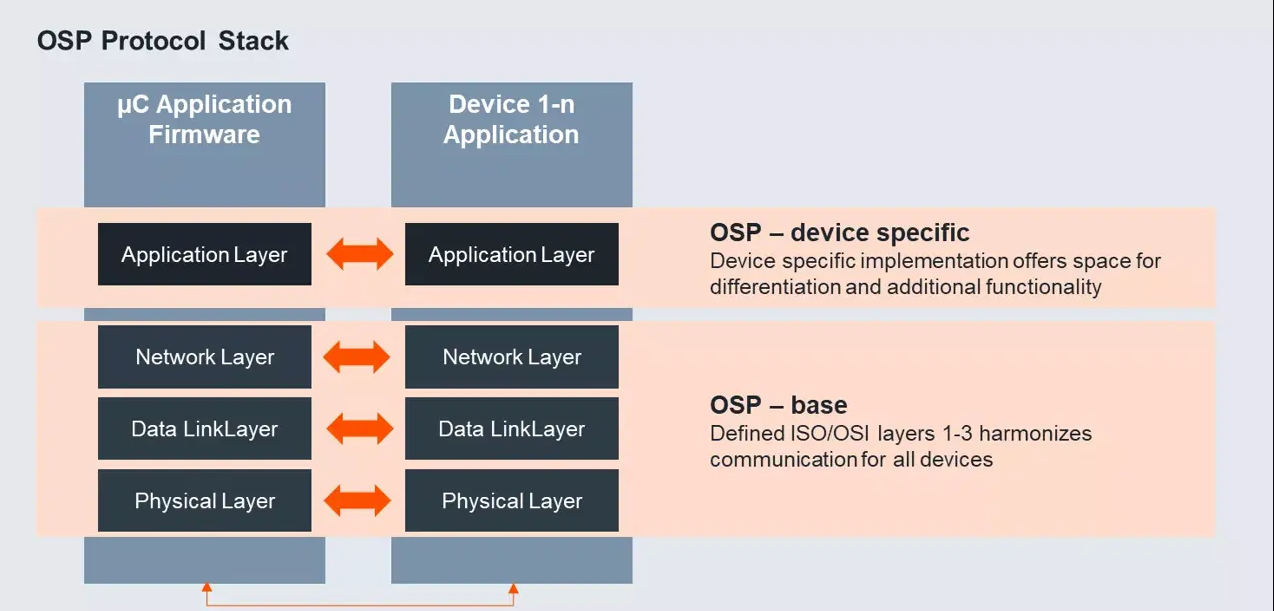 Bildquelle: https://ams-osram.com/de/innovation/technology/open-system-protocol Mit dem AS1163 steht nun ein weiterer LED-Treiber-Baustein am Start, der diesen Standard zu implementieren sucht
-
 Bild
Bild
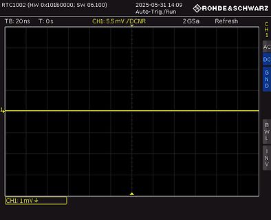
Oszilloskop-Screenshot mit flacher Linie
RTC1002 (HW 0x101b0000; SW 06.100) 2025-05-31 14:09 ROHDE & SCHWARZ Auto-Trig./Run TB: 20ns T: 0s CH1: 5.5mV/DCNR 2 GSa Refresh CH1 AC DC GND 1 CH1: 1mV
-
 Bild
Bild
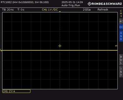
Oszilloskop-Screenshot mit flacher Linie
RTC1002 (HW 0x101b0000; SW 06.100) 2025-05-31 14:09 ROHDE & SCHWARZ Auto-Trig./Run TB: 20ns T: 0s CH1: 1V/DC 2 GSa Refresh CH1 AC DC GND +T CH1: 2V
-
Thread
Sicherheitschraube: Name? Werkzeug?
Sicherheits-Bitsatz/dp/B000K2PEZE/262-2242073-8453855?th=1 https://m.media-amazon.com/images/I/815uebXm0uL._AC_SL1500_.jpg Foto einzeln, der Fotograf war ungeduldig, die hängen schief drin. Jedenfalls ließen sich meine Schrauben herausdrehen, wenn ich irgendwie einen Schlitz in den Kopf bekäme.
' ich nicht. https://produkte.kopp.eu/de/produkt/powerversal-4-fach-erhoehter-beruehrungsschutz-14m-zuleitung-farbe-schwarz-silber-2/ Da steht /wiederanschließbar/. Und auf dem Bild kann man die Schraubenköpfe der einzelnen Doseneinsätze erkennen. "Wiederanschließbar" steht auch bei der hier
-
Thread
Skyteam Skymax Laderegler - Ausgang
ausgegangen, dass der Laderegler aus der Lichtmaschinen-Wechselspannung saubere (halbwegs glatte) 12-14.5 VDC macht. Heute den neuen Regler angesteckt und OHNE Batterie (da momentan nicht vorhanden) aber mit einem 200 Ohm - Lastwiderstand am laufenden Moped betrieben und direkt an dessen Ausgang gemessen
dann nur den Feld-/Erregerstrom so ein Gratuliere zur Rep. Kleine Korrektur: Hier isses eine AC-LiMa, die ein Phasenabschnitt-Regler bändigt (Schema im Bild (Dank an Ewald)).
-
Thread
Querschnittsfläche Ferritkern
Ich habe einen (aufgeschnittenen) Übertrager und brauche für eine Berechnung die Querschnittsfläche AC ("cross-sectional area of the core in cm2") Wie misst man die bzw. welche Fläche ist hier bei so einem Planartransformer relevant?
Teil hat 10,4mm Durchmesser. Das wäre dann eine Gesamtberührfläche von (19mm*2,3mm)*2 + (5,2mm)²*3,14 = 1,72cm² ? Wobei der Querschnitt dann die Hälfte sein sollte, also 0,86cm² ?
-
Thread
Heißdrahtschneider ohne Widerstandsdraht bauen
des Hitzdrahtlaubsägenutzers deutlich weniger beeinträchtigt als mit dem ersten Bier, oder Joint mit 14 hinter der Scheune. Old-Papa
Als Stromquelle verwende ich ein billiges Trafo Schweißgerät - die schweren Dinger. Wird auf der AC Seite mit einem billigen China Dimmer gesteuert. Damit bekomme ich so ziemlich alles zum glühen. Angefangen vom dünnen Widerstandsdraht bis zu den Metallschienen aus Scheibenwischern. Walta
-
Thread
Vermutliches TMS320C6xx-Binary disassemblieren
0x0041008a 5210 0x003300D3 ADDK.S2 26113,B0 5214 0x003600D8 SUB.L1 -16,A13,A0 5218 0x003900D9 SUB.L1 8,A14,A0 521c 0x010500DA SUB.L2 8,B1,B2 5220 0x0105007D STW.D2T1 A2,*+B14[1280] 5224 0x0060007E STW.D2T2 B0,*+B14[24576] 5228 0x0060007E STW.D2T2 B0,*+B14[24576] 522c 0x010B007D STW.D2T1 A2,*+B14[2816
0x01090085 LDHU.D2T1 *-B2[8],A2 525c 0x01070085 LDHU.D2T1 *-B1[24],A2 5260 0x0107013C STB.D2T1 A2,*+B14[1793] 5264 0x01090086 LDHU.D2T2 *-B2[8],B2 5268 0x0109013C STB.D2T1 A2,*+B14[2305] [/code] Aber die .word deuten darauf hin dass da nur Rauschen übersetzt wurde. Ich konnte auch nichts finden was
-
 Bild
Bild
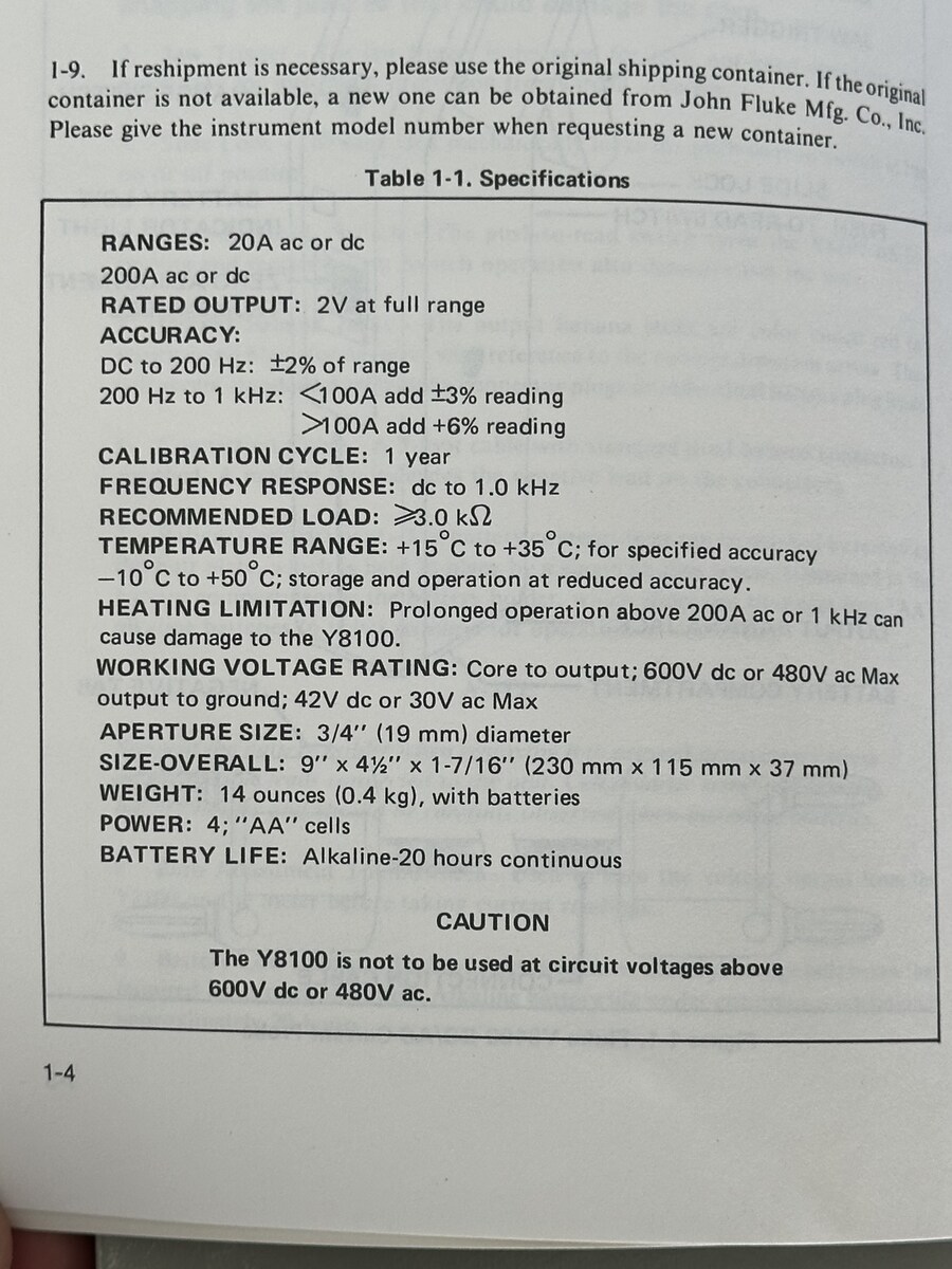
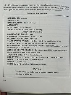
Ausschnitt aus einem Datenblatt eines Messgeräts
50°C; storage and operation at reduced accuracy. HEATING LIMITATION: Prolonged operation above 200A ac or 1 kHz can cause damage to the Y8100. WORKING VOLTAGE RATING: Core to output; 600V dc or 480V ac Max output to ground; 42V dc or 30V ac Max APERTURE SIZE: 3/4" (19 mm) diameter SIZE-OVERALL: 9" x 4 1/2" x 1-7/16" (230 mm x 115 mm x 37 mm) WEIGHT: 14 ounces (0.4 kg), with batteries POWER: 4; "AA" cells BATTERY LIFE: Alkaline-20 hours continuous CAUTION The Y8100 is not to be used at circuit voltages above 600V dc or 480V ac. 1-4
-
Thread
wie definiert sich eine PV-Inselanlage?
Netzbetreiber steuerbar sein. >> >> Wo steht das? Gilt das nicht nur wenn Du die Vergünstigung nach §14 EnWG >> haben möchtest? > > Das steht in §14 EnWG. Du musst den nur richtig lesen. > Details dann bei der BNA. > > Oliver Warum soll der §14 gelten, wenn ich dem Netzbetreiber den Anschluss
Netzbetreiber steuerbar sein. >>> >>> Wo steht das? Gilt das nicht nur wenn Du die Vergünstigung nach §14 EnWG >>> haben möchtest? >> >> Das steht in §14 EnWG. Du musst den nur richtig lesen. >> Details dann bei der BNA. >> >> Oliver > > Warum soll der §14 gelten, wenn ich dem Netzbetreiber den
-
Thread
Bin zu doof Datenblätter zu finden.
Ist der SO14 ein AC/DC LED Buck? Dann suche mal weiter nach Marvell 88EM8187 (passt auch zu MRVL) Am besten auf Baidu.com
-
 Bild
Bild
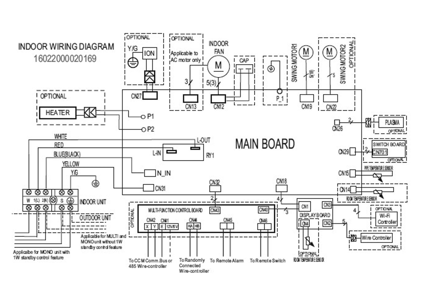
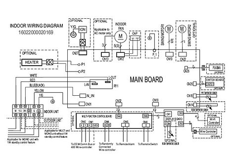
Indoor Wiring Diagram für Klimaanlage
INDOOR WIRING DIAGRAM 16022000020169 Y/G ION OPTIONAL Applicable to AC motor only M CAP SWING MOTOR1 SWING MOTOR2 OPTIONAL P1 CN19 CN22 CN26 PLASMA OPTIONAL SWITCH BOARD CN7011 CN15 OPTIONAL TEMPERATURE SENSOR CN14 CN29 MAIN BOARD P1 P2 HEATER WHITE RED BLUE(BLACK) YELLOW
-
 Bild
Bild
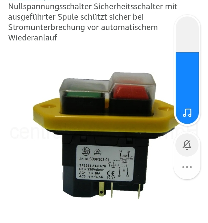
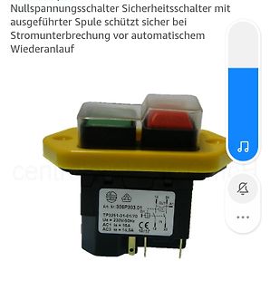
Tripus Sicherheitsschalter Nullspannungsschalter
Stromunterbrechung vor automatischem Wiederanlauf tripus Art. Nr. 306P303.01 TP3251-31-01/70 Ue = 230V/50Hz AC1 Ie = 16A AC3 Ie = 14,5A 14 24 OUT A1 01 IN 13 23 CE 10/17
-
Thread
Reparatur Split-Klima - SNT - Diode SR315
liegt denn der nicht bestückte C3 zu dieser Diode? so ist es tatsächlich - C3 liegt in Reihe mit R14/R15 parallel zur Diode R14 / R15 sind parallel Ich habe noch mal bei Power Integrations im Beispiel-Schaltplan geschaut: Die setzen auch keinen Snubber ein - aber als Diode eine BYV28-200 Die
> so ist es tatsächlich - C3 liegt in Reihe mit > R14/R15 parallel zur Diode R14 / R15 sind parallel Yo, so viel dazu... war wohl zu teuer. Ich würde Dir aber auf jeden Fall zu einer 200V Diode raten, damit das zuverlässig wird. HER303 z.B. könnte man
-
Thread
1600W Paneele an 800W Wechselrichter anschließen
so regeln, dass immer nur der erlaubte > Maximalstrom am Eingang fliesst. Du bekommst Umrichter (AC/AC) und Wechselrichter (DC/AC) nicht sortiert.
regeln, dass immer nur der erlaubte >> Maximalstrom am Eingang fliesst. > Du bekommst Umrichter (AC/AC) und Wechselrichter (DC/AC) nicht sortiert. Jepp - sorry, falschen Begriff verwendet :-)
-
 Bild
Bild
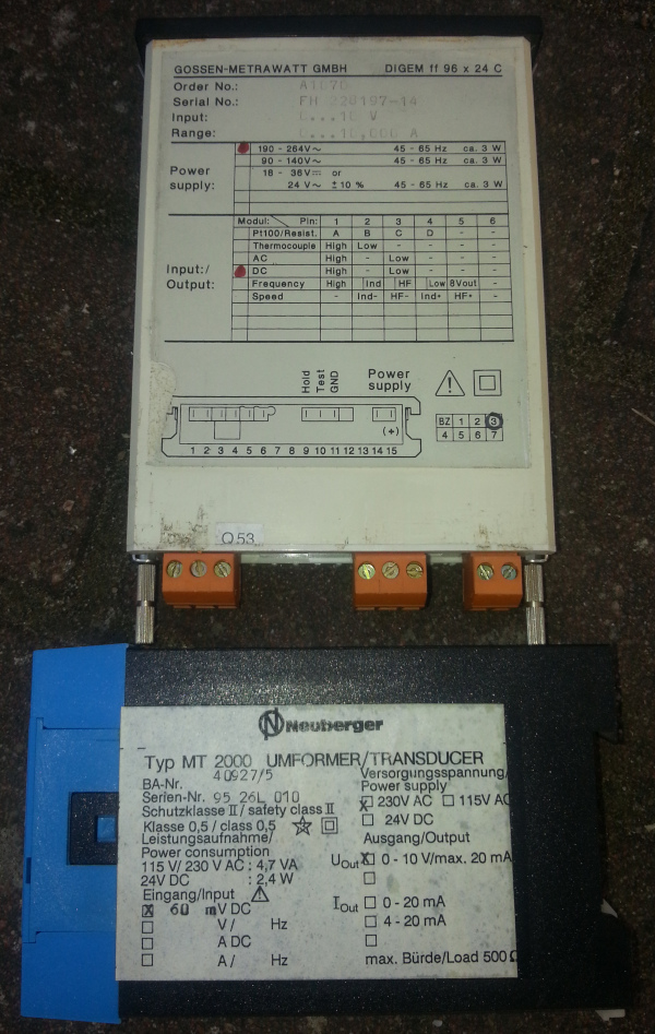
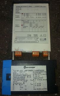
Typenschilder von Gossen-Metrawatt und Neuberger Transducern
GOSSEN-METRAWATT GMBH DIGEM f9 96 x 24 C Order No.: A107C Serial No.: FH 220197-14 Input: 10...110V AC Range: 190-264V~ 45-65Hz ca. 3W 90-140V~ 45-65Hz ca. 3W Power supply: 16-36V~ 45-65Hz ca. 3W 24V+ ca. 3W Module/Pin/1/2/3/4/5/6 Thermocouple A B C D - AC High Low - DC High Low 8Vout
-
Thread
Linearregler sterben
CQAgjOCmC0DsIAYB0AWAHLMYBsBWAnIQEwq4qwDM8uCIuIKFdMWAUAE4hGxEhq0U0KPrVq5WAZ3Bhe-cLGwjEygGYBDADYTIrAO4N0ICrl5Zex3glYBjA2iUpDFhoiQJ378uApIKFfCS4FES4BDwUEKKsGvKKctyyoq4eXtBgSLAIwUREFNgU6NjcKDDwVgBu0uYmVUpJKLRgSaJI4gDmtc5mRtj2UQAmRkIOhvEg-ZDqAK4aAC6sAPZGINjCtA2EXI1IirTmRovKq8ob8KsCSKZcyhSsgssAYpHJHgiRbu5NEGkgAMJqAAc1NYAJazNQAO2sOnuwieymQb3Abm+EAAkhD+lNrOCoTC+iB4Y1wEifgAlSASEESXHQ1gAC3ALluQA
Google mal nach Troubleshooting_Analog_Circuits.pdf und scroll durch nach LDOs. Kapitel 14 ciao gustav
-
Thread
Arduino Nano Störungen und Durchbrennen
. > > Wir wissen nicht wie viel Leistung dein Kompressor zieht, aber das > Relais sollte eine AC3 Rating haben das über dem Kompressorstrom liegt. Es ist ein Kühlschrank-Kompressor mit 80W und er Anlaufstrom beträgt max.2A, wenn er es nicht schafft, anzulaufen. > Deine 12V gehen in einer
strikt trennen, aber da ist irgendwas beim designen gewaltig schief gelaufen, siehe 06.05.2025 20:14
-
Thread
PV Rechner für Bezug und Verbrauch im Jahr
viel wie wir brauchen - sind ja auch die ertragsreichsten Monate. Laut Durschnittsangaben also etwa 14 kWh an Tag im Mai. Ca. Ertrag pro Monat am Gesamtertrag: Jan 2% Feb 4% Mrz 10% Apr 11% Mai 12% Jun 13% Jul 13% Aug 12% Sep 10% Okt 7% Nov 3% Dez 2% Hinzu kommt, in den Wintermonaten
kann ggf. auch aus der Batterie erfolgen. Nicht vergessen bei der Berechnung, die Batterieverluste (AC-Kopplung ca.1/3; DC ca. 1/5..1/6).
-
 Bild
Bild
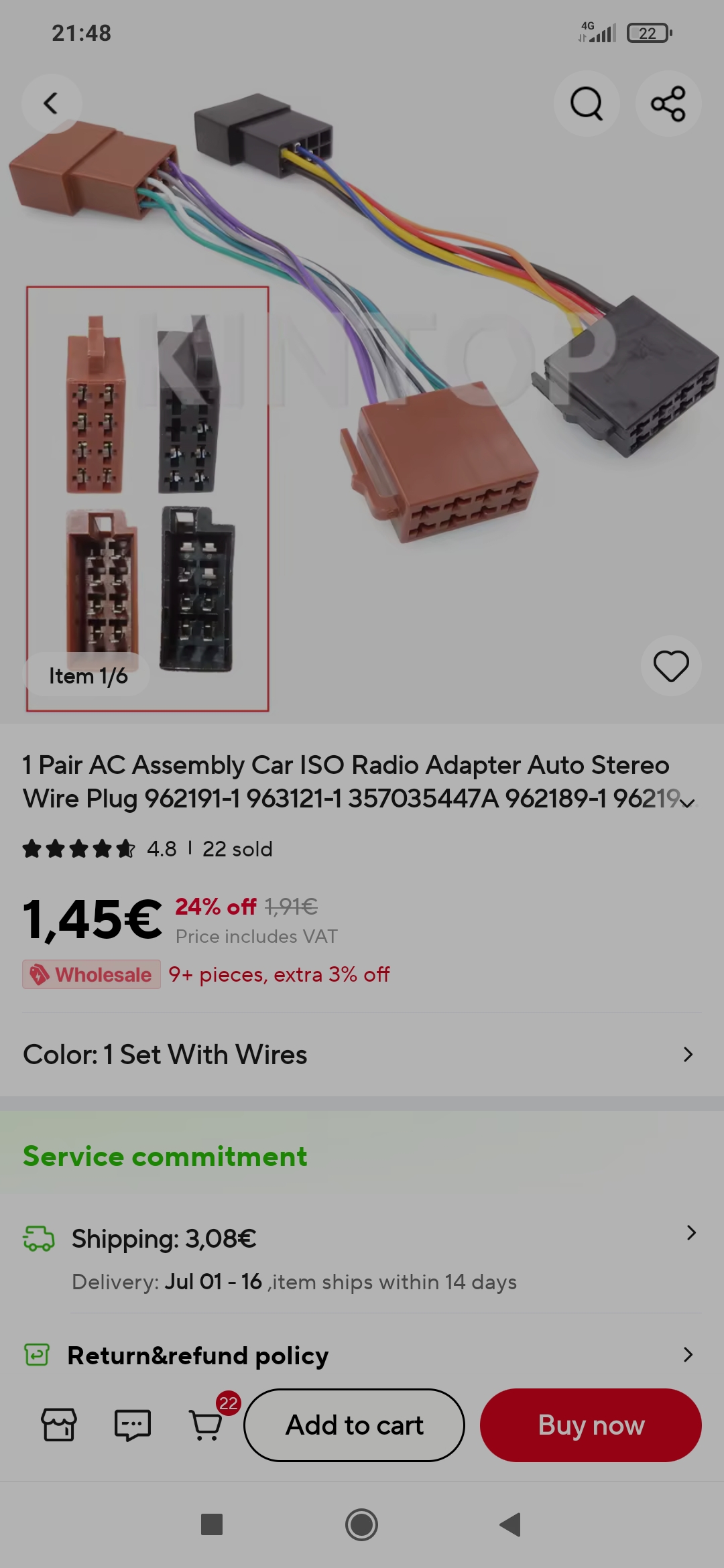
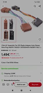
Screenshot eines Online-Shops für Auto-Radio-Adapterkabel
21:48 40 Item 1/6 1 Pair AC Assembly Car ISO Radio Adapter Auto Stereo Wire Plug 962191-1 963121-1 357035447A 962189-1 96219... 4.8 | 22 sold 1,45€ 24% off 1,91€ Price includes VAT Wholesale 9+ pieces, extra 3% off Color: 1 Set With Wires Service commitment Shipping: 3,08€ Delivery: Jul 01 - 16, item ships within 14 days Return&refund policy Add to cart Buy now
-
Thread
innenwiderstand Röhrenmodell mit ltspice ermitteln
schrieb im Beitrag #7869406: > soweit war ich selbst , die frage ist wie mache ich das in ltspice ? AC Analyse, und Stromquelle mit DC=0 und AC=1 anhängen.
Beitrag #7869406: >> soweit war ich selbst , die frage ist wie mache ich das in ltspice ? > > AC Analyse, und Stromquelle mit DC=0 und AC=1 anhängen. Gitterstromquelle DC=0 und zwischen Anode Kathode die Stromquelle mit AC=1 schalten ? oder verstehe ich das nun falsch, aber wo im schaltplan
-
Thread
Strom im mA Bereich mit Oszi messen
auf den ersten Blick vielleicht so aus, aber Das billige Zeug passt einfach nicht.. kann oft nur AC, oder ist vom Messbereich / Auflösung völlig daneben.
> am Oszi schauen was dabei rauskommt? Wäre dann sowas wie eine Rogowski Spule. Kann aber nur AC. Bekommt man da: https://www.pemuk.com/
-
Thread
=== GCC v15 ===
Moin, Bauform B. schrieb im Beitrag #7868596: > Kennt der gcc 13 oder 14 diese Konstruktion schon? Ich glaube nicht. Hier mit einem 14.2.0: [code]gcc -std=c23 bla.c bla.c: In function ‘main’: bla.c:4:19: error: invalid suffix "o123" on integer constant 4 | printf
[c] avr-gcc / Flash / RAM 12.3.0 / 37.468 / 5.078 (Bytes) 13.3.0 / 36.550 / 5.078 (Bytes) 14.3.0 / 36.935 / 3.292 (Bytes) 15.1.0 / 36.769 / 3.292 (Bytes) [/c] Ab 14.x merkt man den Effekt das Konstanten automatisch im Flash landen. µC AVR128DB64.
-
Thread
Treppenlicht Ausschaltvorwarnung LED Strombegrenzer etc.
die Hutschiene. Einfache Zeitwahl, keine ASV. Zuverlässig, weit verbreitet. Finder Serie 14 (z. B. 14.01 oder 14.71) Italienischer Hersteller, robust und einfach. Keine ASV-Funktion. Zeit über Poti einstellbar. Siemens 5TT3062-1 (älteres Modell) Zeitloser Klassiker – hat keine
sogar unter 1 Watt. ASV abschaltbar! Ideal für Neubauten oder Modernisierung. 🔹 Finder Serie 14 (z. B. 14.01, 14.71) LED-kompatibel, auch für kleine Lasten. Geringe Eigenverluste. Auch mit N-Leiter erhältlich. Solide Technik, keine unnötigen Spielereien. 🔹 Theben ELPA 8 / ELPA 9 (