-
Bild
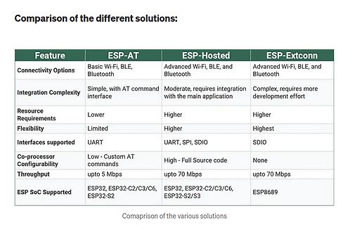
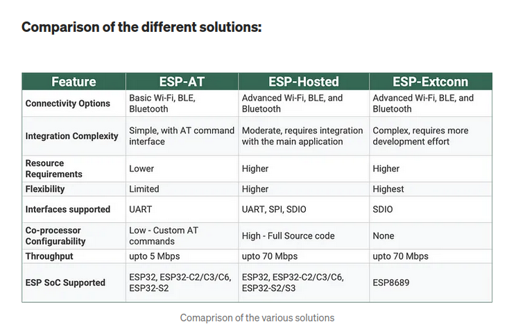
Vergleichstabelle verschiedener ESP-Lösungen
Comparison of the different solutions: Feature ESP-AT ESP-Hosted ESP-Extconn Connectivity Options Basic Wi-Fi, BLE, Bluetooth Advanced Wi-Fi, BLE, and Bluetooth Advanced Wi-Fi, BLE, and Bluetooth Integration Complexity Simple, with AT command interface
in „Raspberry Pi Pico 2, Windows 7 Embedded und mehr“ · Mikrocontroller und Digitale Elektronik · · Screenshots
-
Bild
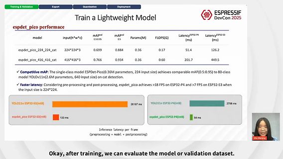
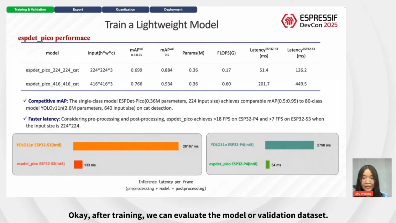
Präsentation von Performance-Daten eines Lightweight-Modells
Lightweight Model espdet_pico performace model input(h*w*c) mAPval mAPval Params(M) FLOPS(G) Latency ESP32-P4 (ms) Latency ESP32-S3 (ms) espdet_pico_224_224_cat 224*224*3 0.699 0.884 0.36 0.17 51.4 126.2 espdet_pico_416_416_cat 416*416*3 0.766 0.934 0.36 0.60 201.7 449.5 Competitive mAP: The single-class
in „Espressif Devcon 2025 - der Sieger läuft samt Beute vom Feld“ · Mikrocontroller und Digitale Elektronik · · Fotos
-
Datei
main.cpp
#include <stdio.h> #include <avr/eeprom.h> extern "C" { #include "time_convert.h" } #define DMA_TX_ESP_CHANNEL DMA.CH2 #define USART_Netzwerk USARTC0 #define F_CPU 32000000UL #define CLK_Prescaler 0x00 #define PLL_Faktor 16 #define BSEL 3325 #define BSCALE 0xFD volatile uint32_t zaehlerstand =202000;
in „Probleme mit dem DMA beim xMega32A4“ · Mikrocontroller und Digitale Elektronik ·
-
Datei
LoRa_Sender.ino
/*** LoRa-Geraffel ***/ #include <TTN_esp32.h> // For Testing/TestApplication, set to your Values!!! const char* devEui = "7788998877665544"; const char* appEui = "7788998877665544"; const char* appKey = "494136c46837032fd41a9cda30d51e33"; TTN_esp32 ttn ; /*** LoRa End ***/ /*** Display ***/ #include "heltec.h" #define __USE_DISPLAY 1 // 0 = Display Off, 1 = Display On, 2 = Display On only on first Boot after Restart or Reset /*** Display End
in „Digitale Stromzähler auslesen und in DB speichern“ · Mikrocontroller und Digitale Elektronik ·
-
PDF
nodemcu-32s_product_specification-2.pdf
℃ Copyright © 2019 Shenzhen Ai-Thinker Technology Co., Ltd All Rights Reserved第 4 页 共 12 页 Nodemcu-32s WIFI MODULE V1 2. Pin Definition The ESP-WROOM-32s module has a total of 38 interfaces, as shown in Figure 1, and Table 2 is the interface definition. Figure 1 ESP-WROOM-32s pin diagram 第 5 页 共 12 页
in „Schaltplan für SBC-NodeMCU-ESP32“ · Mikrocontroller und Digitale Elektronik ·
-
PDF
0b-esp8266_system_description_en.pdf
. 2016.07 V1.6 Section 2.1 updated. 2017.01 V2.0 Changed the minimum working voltage of ESP8266EX from 3.0V to 2.5V. Updated Table 1-1. Changed the chip output impedance from 50Ω to 39+j6 Ω; 2017.04 V2.1 Stated that Flash1 and Flash2 on ESP-LAUNCHER are both 32 Mbit; Updated Section 1.4.5.
in „Wassermelder mit ESP8266 realisieren“ · Mikrocontroller und Digitale Elektronik ·
-
Bild
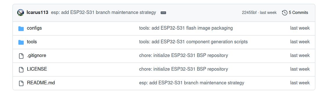
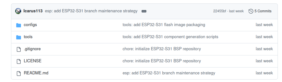
Ausschnitt einer Git-Repository-Dateiliste
Icarus113 esp: add ESP32-S31 branch maintenance strategy 22455bf last week 5 Commits configs tools: add ESP32-S31 flash image packaging last week tools tools: add ESP32-S31 component generation scripts last week .gitignore chore: initialize ESP32-S31 BSP repository last week LICENSE chore: initialize ESP32-S31 BSP repository last week README.md esp: add ESP32-S31 branch maintenance strategy last week
in „Arduino Ventuno Q, Linux für ESP32-S31, OrangePi Zero 4 uvam“ · Mikrocontroller und Digitale Elektronik · · Screenshots
-
Bild
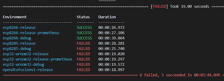
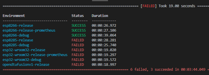
Statusliste eines Build-Prozesses
[FAILED] Took 19.00 seconds Environment Status Duration esp8266-release SUCCESS 00:00:26.972 esp8266-release-prometheus SUCCESS 00:00:27.106 esp8266-debug SUCCESS 00:00:39.064 esp8285-release FAILED 00:00:28.281 esp8285-debug FAILED 00:00:25.740 esp32-wroom32-release FAILED 00:00:19.020 esp32-wroom32-release-prometheus FAILED 00:00:19.297 esp32-wroom32-debug FAILED 00:00:19.572 opendtufusionv1-release FAILED 00:00:18.997 6 failed, 3 succeeded in 00:03:44.049
in „Wechselrichter Hoymiles HM-xxxx 2,4 GhZ Nordic Protokoll?“ · Mikrocontroller und Digitale Elektronik · · Screenshots
-
Bild
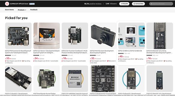
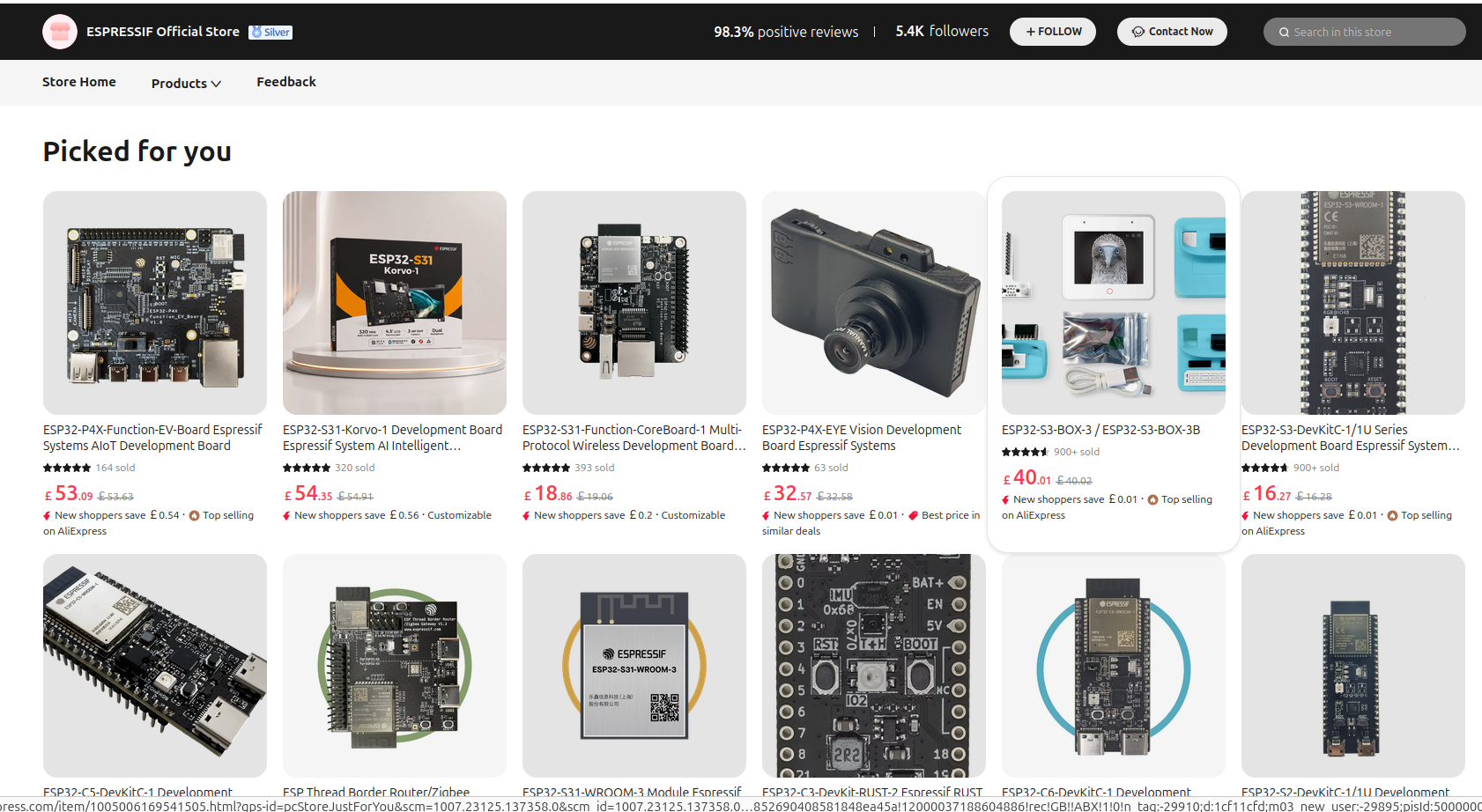
Screenshot eines Online-Shops für ESPRESSIF Elektronik-Komponenten
320 sold £ 54.35 £ 54.91 New shoppers save £ 0.56 Customizable ESP32-S31-Function-CoreBoard-1 Multi-Protocol Wireless Development Board 393 sold £ 18.86 £ 19.06 New shoppers save £ 0.2 Customizable ESP32-P4X-EYE Vision Development Board Espressif Systems 63 sold £ 32.9 £ 32.58 New shoppers save £ 0.01 Best price in similar deals ESP32-S3-BOX-3 / ESP32-S3-BOX-3B 900+ sold £ 40.01 £ 40.02 New shoppers save £ 0.01 Top selling on AliExpress ESP32-S3-DevKitC-1/1U Series
in „ESP32-S31 in Massenproduktion, MERICRON als ESP32-Alternative uvam“ · Mikrocontroller und Digitale Elektronik · · Screenshots
-
PDF
9b-esp8266-low_power_solutions_en_0.pdf
ESP8266 Low Power Solutions Version 1.1 Copyright © 2016 About This Guide This document introduces ESP8266 sleep mode and low-power solutions with the following topics: Chapter Title Subject Chapter 1 Overview
in „2 Grundsatzfragen zu WLAN und ESP8266“ · Mikrocontroller und Digitale Elektronik ·
-
PDF
9b-esp8266-low_power_solutions_en_0.pdf
ESP8266 Low Power Solutions Version 1.1 Copyright © 2016 About This Guide This document introduces ESP8266 sleep mode and low-power solutions with the following topics: Chapter Title Subject Chapter 1 Overview
in „esp8266 sleep mode“ · Mikrocontroller und Digitale Elektronik ·
-
PDF
4a-esp8266_at_instruction_set_en.pdf
default IP address of the ESP8266 of the ESP8266 Station. Station. Espressif 32/62 2019.02 4. Wi-Fi AT Commands +CIPSTA_DEF:<ip> +CIPSTA_DEF:<gateway> Response OK +CIPSTA_DEF:<netmask> OK ⚠ Notice: • <ip>: string parameter, the
in „Eigenartiges Verhalten von Li-Batterien“ · Analoge Elektronik und Schaltungstechnik ·
-
PDF
4a-esp8266_at_instruction_set_en.pdf
default IP address of the ESP8266 of the ESP8266 Station. Station. Espressif 32/62 2019.02 4. Wi-Fi AT Commands +CIPSTA_DEF:<ip> +CIPSTA_DEF:<gateway> Response OK +CIPSTA_DEF:<netmask> OK ⚠ Notice: • <ip>: string parameter, the
in „ESP8266 USB Adapter an zwei Pc benutzen.“ · Mikrocontroller und Digitale Elektronik ·
-
Datei
Error.txt
[c] undefined C:\platformio\packages\toolchain-xtensa-esp32s3\bin\xtensa-esp32s3-elf-gdb.exe: warning: Couldn't determine a path for the index cache directory. Reading symbols from C:\ESP32_S3_Test\.pio\build\esp32-s3-devkitm-1\firmware.elf... PlatformIO Unified Debugger -> https://bit.ly/pio-debug PlatformIO: debug_tool = esp-builtin PlatformIO: Initializing remote target... Open On-Chip Debugger v0.11.0-esp32-20220706 (2022-07-06-15:48) Licensed under GNU GPL v2 For bug reports, read http://openocd.org/doc/doxygen/bugs.html
in „ESP32-S3-ZERO debugging“ · Mikrocontroller und Digitale Elektronik ·
-
Bild
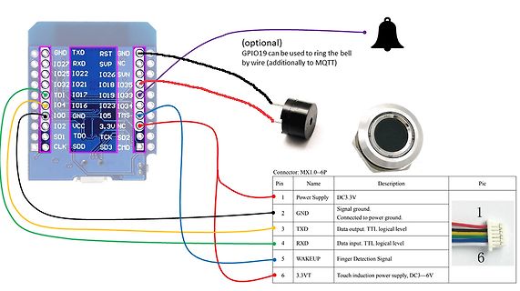
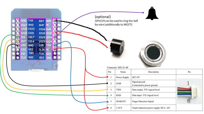
Verdrahtungsplan eines Mikrocontrollers mit Sensor und Glocke
(optional) GPIO19 can be used to ring the bell by wire (additionally to MQTT) GND TXD RST GND IO27 RXD SUP NC IO25 IO32 IO21 IO26 SUN IO17 IO18 IO35 TDI IO4 IO16 IO23 IO33 IO0 IO2 VCC 3.3V NC SDI IO1 TCK SD2 CLK SDD SD3 CMD Connector: MX1.0-6P 1 Power Supply DC3.3V 2 GND Signal ground. Connected to power ground. 3 TXD Data output. TTL logical level 4 RXD Data input. TTL logical level 5 WAKEUP Finger Detection 6 3.3VT Touch induction power supply, DC3-6V
in „Touch-Erkennung Finegrabdrucksensor r503“ · Haus & Smart Home · · Diagramme
-
Bild
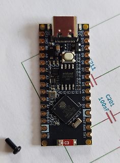
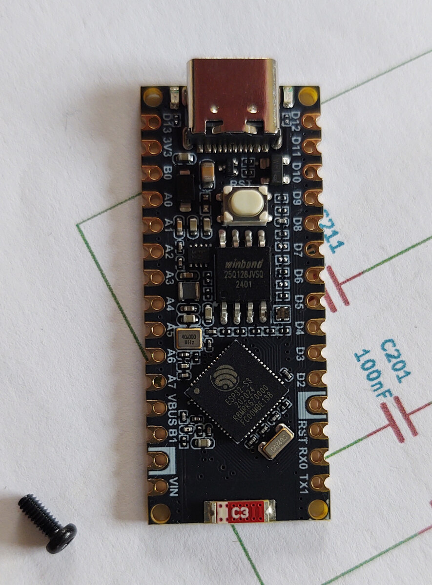
Adafruit Trinket M0 Mikrocontroller Board
A2 A3 A4 A5 A6 A7 VBUS B1 VIN D12 D11 D10 D9 D8 D7 D6 D5 D4 D3 D2 D1 D0 RST winbond 25Q128JV50 2401 ESP32-S3 ESP32-S3 800MHz Xtensa FCH00RE S3 R51 RX0 TX1 C3
in „[V] Bausatz 8 mal Temperaturmessung, 2 mal AC-Strommessung WLAN“ · Markt · · Platinenfotos
-
Bild
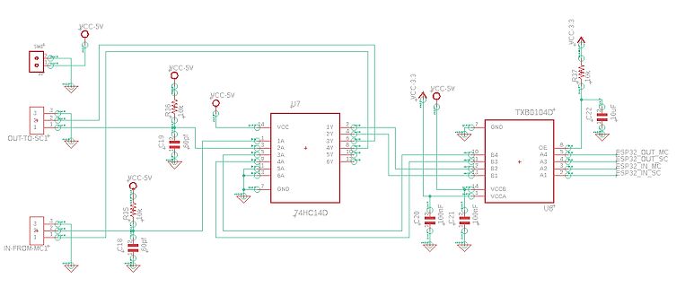
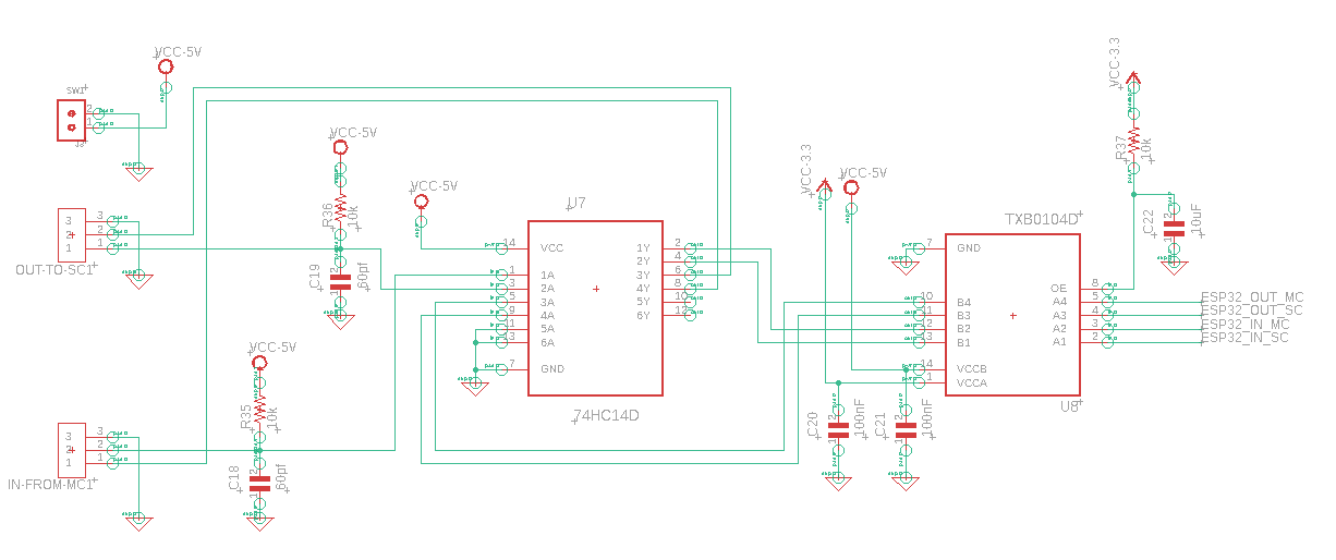
Schaltplan mit Logikgatter und Pegelwandler
, VCC-3.3, R37, 10k, C22, 10uF, TXB0104D, OE, GND, B4, B3, B2, B1, VCCB, VCCA, U8, A1, A2, A3, A4, ESP32_OUT_MC, ESP32_OUT_SC, ESP32_IN_MC, ESP32_IN_SC, C20, 100nF, C21, 100nF, IN-FROM-MC1, R35, 10k, C18, 60pF
in „Schmitt-Trigger 74HC14 mit Level Shifter“ · Mikrocontroller und Digitale Elektronik · · Schaltpläne
-
Bild
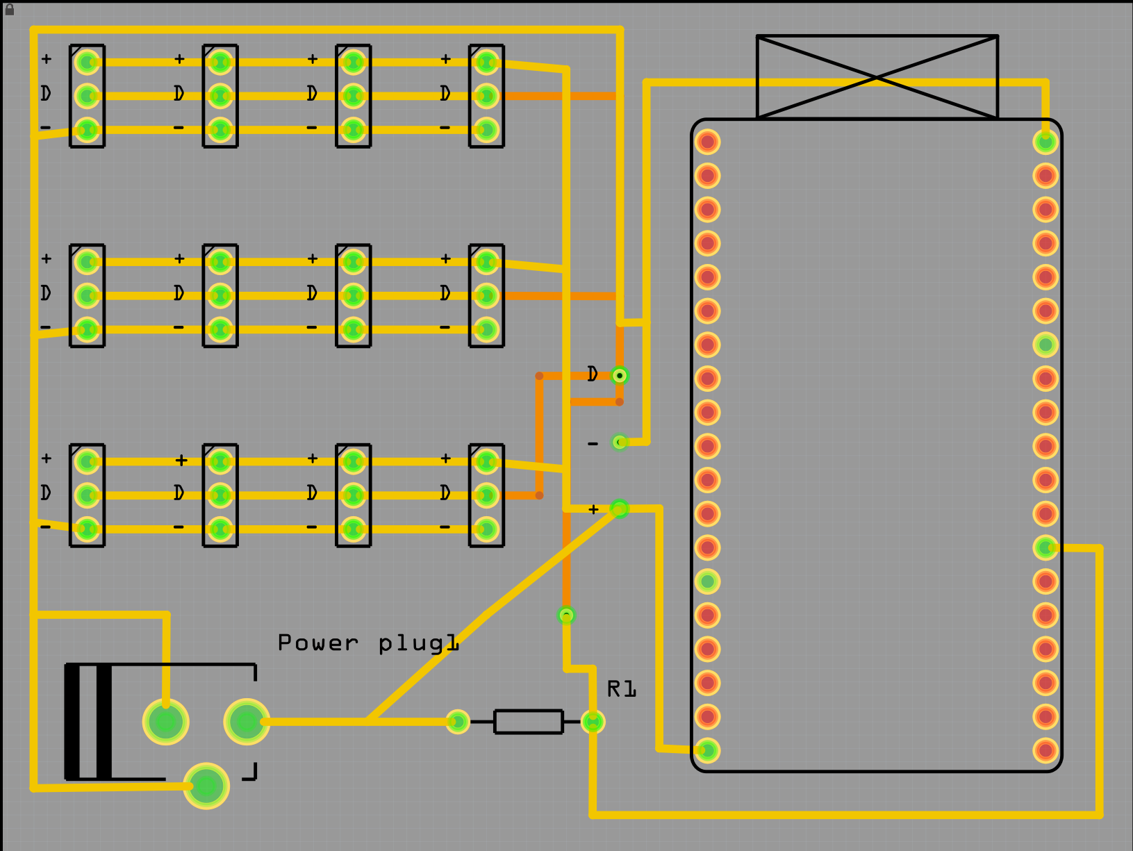
CAD-Ansicht eines Leiterplatten-Layouts
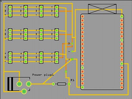
D + D - Power plug1 R1
in „ESP32 kann sich nicht mit dem WLAN verbinden“ · Mikrocontroller und Digitale Elektronik · · Layouts
-
Datei
Sipdial_esp32.ino
char *pSipPassWd; const char *pMyIp; int iMyPort; const char *pDialNr; const char *pDialDesc; uint32_t callid; uint32_t tagid; uint32_t branchid; int iAuthCnt; uint32_t iRingTime; uint32_t iMaxTime; int iDialRetries; int iLastCSeq; void AddSipLine(const char* constFormat , ... ); bool AddCopySipLine
-
Datei
esp32_webserver.ino
;margin-bottom: 10px;}\n"; ptr += "</style>\n"; ptr += "</head>\n"; ptr += "<body>\n"; ptr += "<h1>ESP32 Web Server</h1>\n"; ptr += "<h3>Using Station Mode (STA)</h3>\n"; if (led1stat == S_OFF) {ptr += "<p>LED1 Status: OFF</p><a class=\"button button-blink\" href=\"/led1blink\">BLINK</a>\n";} else if
in „ESP8266 - WebServer mit blinkender LED nach Submit/Form“ · Mikrocontroller und Digitale Elektronik ·
-
Datei
ESP32_SPI.ino
); SPI.setDataMode(SPI_MODE0); SPI.setClockDivider(SPI_CLOCK_DIV8); //divide the clock by 8=2 MHz @ESP32 } void loop (void) { char c; digitalWrite(SS, LOW); // enable Slave Select // send test string for (const char *p = "Hello, world! We are online over SPI\n\r" ; c = *p; p++) { retchr=SPI.transfer
in „ESP32 - SPI funktioniert nicht“ · Mikrocontroller und Digitale Elektronik ·
-
Datei
ESP32_Zirkulation.txt
#include <WiFi.h> const char* ssid = "FRITZ!Box Fon WLAN 7270"; const char* password = "12345678"; WiFiServer server(80); const unsigned long intervall15 = 900000; //15min unsigned long currentMillis15 = 0; // speicher für 15 min boolean minutena = false; boolean minutenb = false; int tasterPinOn = 4; int tasterPinOff = 12; void setup() { Serial.begin(115200); pinMode(5, OUTPUT); // set the LED pin mode pinMode(tasterPinOn,INPUT); pinMode(tasterPinOff,INPUT); delay(10); digitalWrite(5, HIGH); delay(10); // We start by connecting to a WiFi network Serial.println(); Serial.println(); Serial.print
in „ESP32 Ansteuerung einer Pumpe über WLAN“ · Mikrocontroller und Digitale Elektronik ·
-
Datei
ESP32_SPItest.ino
#include <SPI.h> SPIClass SPI1(HSPI); void setup() { pinMode(4,OUTPUT); // Reset MAX3421 digitalWrite(4,0); delay(5000); digitalWrite(4,1); // Pins for clk, miso, mosi, ss SPI1.begin (14, 32, 13, 15); SPI1.setHwCs(true); } void loop() { SPI1.beginTransaction(SPISettings(3000, MSBFIRST, SPI_MODE0)); SPI1.transfer16(0xA200); // Write 00 to R20 SPI1.endTransaction(); delay(1000); SPI1.beginTransaction(SPISettings(3000, MSBFIRST, SPI_MODE0)); SPI1.transfer16(0xA2ff); // Write 00 to R20 SPI1.endTransaction(); delay(1000); }
in „Frage zu SPI.beginTransaction“ · Mikrocontroller und Digitale Elektronik ·
-
Datei
LOG_ESP32.txt
22:04:48.839 -> rst:0x1 (POWERON_RESET),boot:0x13 (SPI_FAST_FLASH_BOOT) 22:04:48.839 -> configsip: 0, SPIWP:0xee 22:04:48.839 -> clk_drv:0x00,q_drv:0x00,d_drv:0x00,cs0_drv:0x00,hd_drv:0x00,wp_drv:0x00 22:04:48.839 -> mode:DIO, clock div:1 22:04:48.839 -> load:0x3fff0018,len:4 22:04:48.839 -> load:0x3fff001c,len:1044 22:04:48.886 -> load:0x40078000,len:10124 22:04:48.886 -> load:0x40080400,len:5856 22:04:48.886 -> entry 0x400806a8 22:04:48.980 -> Configure ACAN2515 22:04:49.964 -> Bit Rate prescaler: 32 22:04:49.964 -> Propagation Segment: 8 22:04:49.964 -> Phase segment 1: 8 22:04:49.964 -> Phase segment
-
Datei
ESP32_main.cpp
#include <Arduino.h> #include <esp32_can.h> void printFrame(CAN_FRAME *message) { Serial.print(message->id, HEX); if (message->extended) Serial.print(" X "); else Serial.print(" S "); Serial.print(message->length, DEC); for (int i =
in „CAN und MCP2515 - Kein Senden möglich“ · Mikrocontroller und Digitale Elektronik ·
-
PDF
Schema_ESP32.pdf
Power 5V ESP32 GND 9 +3V3 3 1 D 38 GND 2 GND N GND 37 GND +5V_EXT VCC_12V 3 3V3 G IO23 36 U6 EN 4 EN IO22 35 LM2596S-5.0 5 SENSOR_VP TXD0 34 RXD C3 C4 SENSOR_VN RXD0 TXD L1 1 100nF 22uF 6 IO34 IO21 33 IO21 47uH
in „ESP32 USB - C Schema“ · Mikrocontroller und Digitale Elektronik ·
-
PDF
ESP32Radio.pdf
1 2 3 4 5 6 7 8 +3.3V R16 A1 +3.3V VCC PWR_FLAG ESP32-WROVER-I +9V þÿ2,2µ C57 V 10k 8 AVDD LineOUT_R 5 2 1 2 VDD3V3 CPVDD 8 R43 TL082 1 2 1 1 1 C C15 20 DVDD R38 k 47k 3 + C þ R 2 2 C 5 C20 C26 C27 C28 C29 C31 18 V 1 1 A J6 V IO39 IO39_SENSOR_VN þÿ22µ
in „TDA7439DS Störgeräusche und ein kochender TDA7377“ · Mikrocontroller und Digitale Elektronik ·
-
Bild
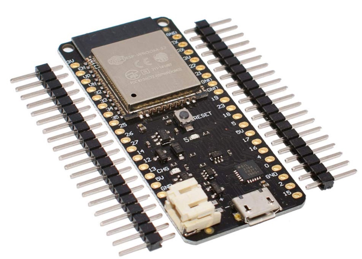
ESP-WROOM-32 Mikrocontroller-Board mit Pin-Leisten
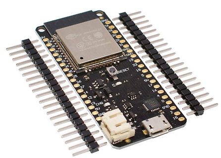
ESP-WROOM-32, CE, 211-161007, FCC ID: 2ACTZ-ESPWROOM32, 3V, UP, UN, 32, 33, 34, 25, 26, 27, 14, 13, CHG, 5V, GND, GND, 3U, 22, 21, GND, QNT, 19, 23, 18, 5V, 17, 16, 0, GND, 2, 15, RESET, SIL, 2154, 2025
in „nodemcu mit akku betreiben und per Laderegler wieder laden“ · Mikrocontroller und Digitale Elektronik · · Platinenfotos
-
PDF
Airframe-Esp32.pdf
2.2nH 0402 P PPII PP IPC2PP4 PP4 4PP0 0PP 4 P COC1 P P IC1 CC OC GND D 2 1 P N 6 5 D D S I U O K 8 ESP32-S3FN8 P 3.3pF P 3.3pF N A A L _ O O X X M T P D C O 2 2 G D D A A P P 0 0T T M _ T T P D D T T G G U U M P MM G GND GND V V X X 3 C D C V VDD 3V3 CL2 PIIC01 LNA_IN GPIO37 PIC142 ADC Ctrl PI0 PI02
in „CP2102 ESP32-S3 USB Verbindung“ · Mikrocontroller und Digitale Elektronik ·
-
Bild
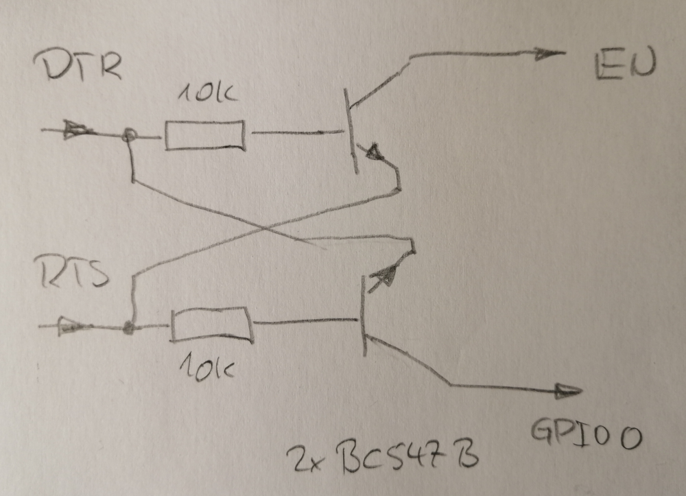
Handgezeichneter Schaltplan mit Transistoren
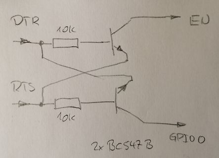
DTR 10k EN RTS 10k GPIO0 2x BC547 B
in „flashing ESP32 via FT232RL“ · Mikrocontroller und Digitale Elektronik · · Diagramme
-
PDF
ESP8266-01S_Modul_Datenblatt.pdf
circuitry, and the entire solution, including front-end module. It is designed to occupy minimal PCB area. ESP8266EX also integrates an enhanced version of Tensilica’s L106 Diamond series 32-bit processor, with on-chip SRAM, besides the Wi-Fi functionalities. ESP8266EX is often integrated with external sensors

-
PDF
T-Internet-POE.pdf
V 3 M3V3 1 38 1 1 1 1 . 6 2 GND GND 37 EMAC_MDC GND 0 . % % % % F n F F 3V3 IO23 2 . . . . 0 0 . 0 ESP32_EN 3 EN IO22 36 EMAC_TXD1 4 4 4 4 GND 1 1 2 1 25 GND IO36 4 SENSOR_VP TXD0 35 ESP32_UARX RXER/PHYAD0 10 IO39 5 SENSOR_VN RXD0 34 ESP32_UATX C13 30pF(NC) IO34 6 33 EMAC_TX_EN GND IO35 7 IO34 IO21 32
in „T-Internet PoE“ · Mikrocontroller und Digitale Elektronik ·
-
Datei
ESP32_BMP280_espNowDeepSleep3.ino
/* ESP32 BMP280 sender with DEEP SLEEP (3 seconds) BMP280 and BME280 sensor can be used: Enable it with the #define in the code You have also to adapt the receiver MAC in the code. external libraries: Temperature
-
Datei
main.asm
beenden cbr jobs,1<<wait_sb ;Warten auf Stand By beenden sei ret ;Sleep shutdown: .db "Shutdown",13,0 ; ESP einschalten ;Timeout sub_ena_timeout: sendtxt esptimotxt sbr jobs,1<<wait_sb ret sub_ena_esp: #if debug sendtxt esp_ein #endif cbr jobs,1<<esp ;Job löschen sbi ddrd,2 ;RS232-Pfad vom ESP einschalten
in „ATMega328 + Si7021 + I2C (Assembler)“ · Mikrocontroller und Digitale Elektronik ·
-
Bild
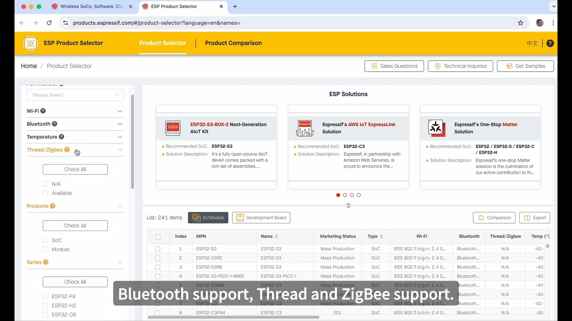
Screenshot des Espressif Product Selectors
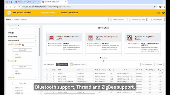
ESP Product Selector Wi-Fi Bluetooth Temperature Thread/Zigbee ESP32-S3-BOX-3 Next-Generation AIoT Kit ESP32-S3 ESP32-S3R2 ESP32-S3R8 ESP32-S3-PICO-1N8R2 ESP32-S3-WROOM-1-N4 Bluetooth Thread/Zigbee support
in „Tag 3 der Espressif DevCon 2024 – von Drohne und Co“ · Mikrocontroller und Digitale Elektronik · · Screenshots
-
Bild
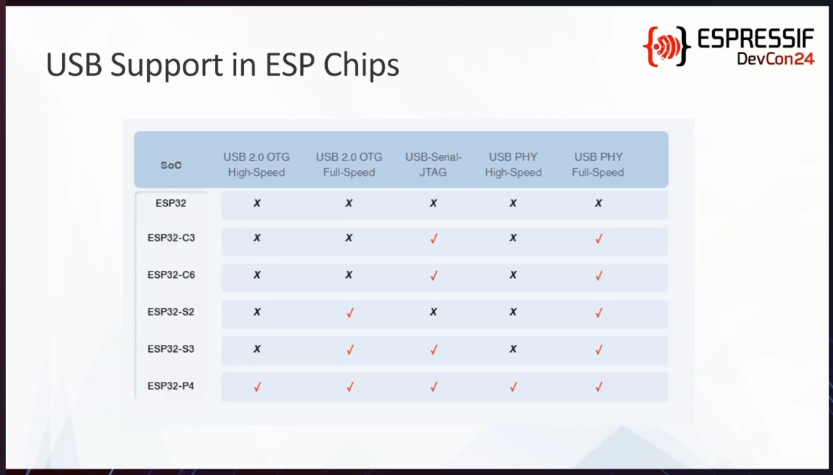
Tabelle zum USB-Support in ESP-Chips
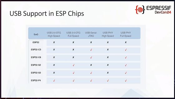
USB Support in ESP Chips ESPRESSIF DevCon24 SoC USB 2.0 OTG High-Speed USB 2.0 OTG Full-Speed USB-Serial-JTAG USB PHY High-Speed USB PHY Full-Speed ESP32 X X X ESP32-C3 X X ✓ X ✓ ESP32-C6 X X ✓ X ✓ ESP32-S2 X ✓ X X ✓ ESP32-S3 X ✓ ✓ X ✓ ESP32-P4 ✓ ✓ ✓
in „Made by Developers, Made For Developers – ESP32 DevCon, Tag 1“ · Mikrocontroller und Digitale Elektronik · · Diagramme
-
Datei
Raumklima_SCD41_V3.py
''' Raumklima Create a webpage access point to show sensor data Hardware: ESP32 (sensor chip temperature) DS18B20 temperature sensor Sensirion SCD41 CO2 sensor MicroPython v1.26.1 on 2025-09-11; Generic ESP32 module with ESP32 External libraries: https://microdot.readthedocs.io
-
Datei
DTZ_Logger_WLAN.ino
/** * DTZ 541 Logger * Version 0.9 * 10.12.2020 P. Rebesky **/ #include <ESP8266WiFi.h> //ESP8266 Core WiFi Library #include <ESP8266WiFiMulti.h> //ESP8266 Core WiFi Library #include <DNSServer.h> #include <ESP8266WebServer.h> //Local WebServer #include <NTPClient.h> #include
in „DTZ541 mMe Datenlogger mit ESP (WEB-Sicht)“ · Mikrocontroller und Digitale Elektronik ·
-
PDF
SCH_ESP32-Ethernet-Kit_A_V1.2_20200528.pdf
5 4 3 2 1 D D System Block: P5V ESP32-ETHERNET-KIT_B PSE GND ESP32-ETHERNET-KIT_A ESP32-ETHERNET-KIT_B RXCM RXCM TXCM TXCM RJ45 1P78 1P78 1P45 1P45 C C Flyback POE PD P5V Transformer TPS23753 Bridge Transformer 5V output DCDC rectifier
in „Arduino Library für Netzwerkchip W5500?“ · Mikrocontroller und Digitale Elektronik ·
-
Bild
Text über CircuitPython Port-Status und Implementierungen
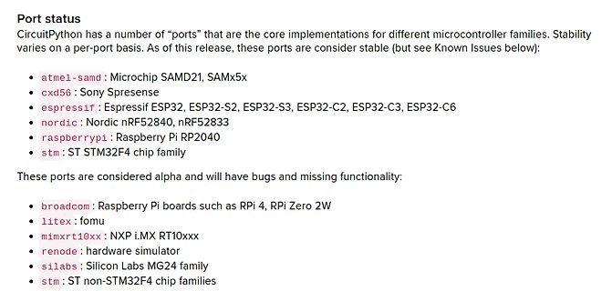
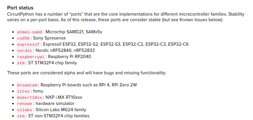
Issues below): atmel-samd : Microchip SAMD21, SAMx5x cxd56 : Sony Spresense esspressif : Espressif ESP32, ESP32-S2, ESP32-S3, ESP32-C2, ESP32-C3, ESP32-C6 nordic : Nordic nRF52840, nRF52833 raspberrypi : Raspberry Pi RP2040 stm : ST STM32F4 chip family These ports are considered alpha and will have
in „Neue Chips, Ubuntu Server für RISC-V, Nachrichten im Hause CircuitPython uvam“ · Mikrocontroller und Digitale Elektronik · · Screenshots
-
Datei
index.html
div> <div class="time-format">Time: <span id="time">--</span></div> <br> <div class="reading temp1">ESP32: <span id="esp32">--</span> <span class="temp1">°C</span></div> <div class="reading temp3">SCD41 T: <span id="scd_t">--</span> <span class="temp3">°C</span></div> <div class="reading temp2
-
Datei
softap_example_main.c
(void* arg, esp_event_base_t event_base, int32_t event_id, void* event_data) { if (event_id == WIFI_EVENT_AP_STACONNECTED) { wifi_event_ap_staconnected_t* event = (wifi_event_ap_staconnected_t*) event_data; ESP_LOGI
in „Falsche Typumwandlung? Einsteigerfrage“ · Mikrocontroller und Digitale Elektronik ·
-
PDF
howto_-tasmota-sml.pdf
Grundlage zu diesem Dokument ist. Viel Erfolg! 3 Hardware Geeignete Hardware für Tasmota: Alle auf dem ESP8266 Chip basierenden Entwicklerboards z.B.: - Wemos D1 mini - NodeMCU - ESP01 Sonoff Hardware Relays sind auch kompatibel. Die verschiedenen Boards unterscheiden sich in Ihrer Anzahl an GPIOs und der
in „Wärmezähler über optische M-Bus-Schnittstelle auslesen“ · Haus & Smart Home ·
-
Datei
http.cpp
------------------------------------------------------------------------------------- */ #include <ESP8266WiFi.h> #include <ESP8266httpUpdate.h> #include <WString.h> #include "base.h" #include "vars.h" #include "wifi.h" #include "version.h" #include "http.h" #include "httpclient.h" #include "stm32flash.h
-
Datei
Makefile.txt
# where to flash blank.bin to erase wireless settings else # Winbond 25Q32 4MB flash, typ for esp-12 # Here we're using two partitions of approx 0.5MB because that's what's easily available in terms # of linker scripts in the SDK. Ideally we'd use two partitions of approx 1MB
-
PDF
ONJU_Schematic.pdf
IJ20 5 D5DOC ESD5V0D5B-TP PI GND P Shield S S02JIP ESD5V0D5B-TP P5 1051330001 GND GND GND LDO GND 3V3_ESP32 3V3_ESP32 USB P P 3V3 3V3_ESP32 R12 R8 R5 10 kOhms 10 kOhms IP0 PI52 P CHIP_PU P GPIO0 0 Ohms P 3V3_ESP32 3V3_ESP32 3V3_ESP32 3V3_ESP32 C3O GND 1 µF P4 P P7 P2 P2 P P J3 CO P C14 C16 C17 C19 C21 C22
in „Bitte um Review meiner erweiterten ONYU-Schaltpläne (Bluetooth-Erweiterung mit CSR8635)“ · Mikrocontroller und Digitale Elektronik ·
-
Datei
dimmer.c
about one event - are we connected to the AP with an IP? */ const int CONNECTED_BIT = BIT0; const u32_t DUTY_CYCLE_MAX = 1024; u32_t dutyCycle = 0; static esp_err_t event_handler(void *ctx, system_event_t *event) { switch(event->event_id) { case SYSTEM_EVENT_STA_START: esp_wifi_connect(); break; case
in „Neues SDK für ESP32“ · Mikrocontroller und Digitale Elektronik ·
-
PDF
2023-04-06_Schematic_ESP32-CAN_draft.pdf
UNFINISHED, UNPRODUCED, UNTESTED ! see https://www.espressif.com/sites/default/files/documentation/esp32-c3-wroom-02_datasheet_en.pdf ESP32 C3 as Fig 7 Peripheral Schematics B limiting LED current to 1mA, B LED we do not want them too bright :) System on Module 3V3 TXD serial R499 ? https://www.espressif.com/sites/default/files/documentation/esp32-c3_hardware_design_guidelinesCAN Controller 3V3 2.6 UART You need to connect a 499 !& resistor to the U0TXD line to suppress the 80 MHz harmonics. red for power yellow for RX, TX and ESP alive indicator
in „ESP32 C3 Wroom - USB Verschaltung“ · Mikrocontroller und Digitale Elektronik ·
-
Bild
Tabelle zum Support-Status von Espressif Chips
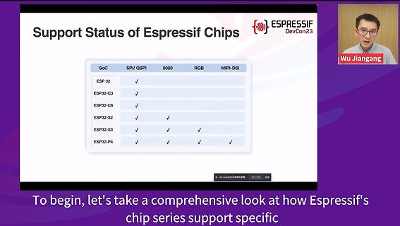
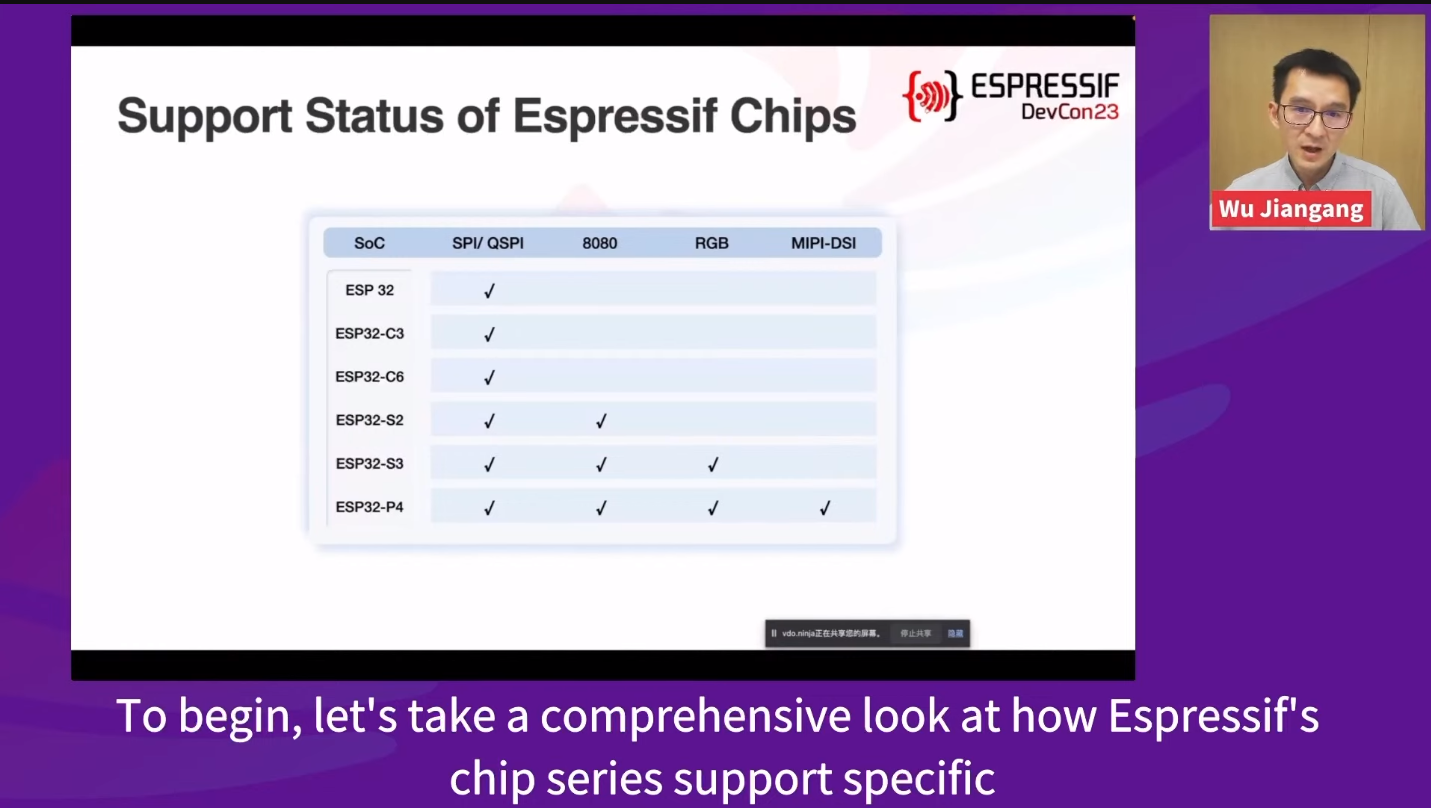
Support Status of Espressif Chips ESPRESSIF DevCon23 Wu Jiangang SoC SPI/ QSPI 8080 RGB MIPI-DSI ESP 32 ESP32-C3 ESP32-C6 ESP32-S2 ESP32-S3 ESP32-P4
in „Espressif DevCon 2023, Tag 2 – Das Ökosystem spricht“ · Mikrocontroller und Digitale Elektronik · · Fotos
-
PDF
0A-ESP8266_Specifications_v4.pdf
circuitry, and the entire solution, including front-end module, is designed to occupy minimal PCB area. ESP8266EX also integrates an enhanced version of Tensilica’s L106 Diamond series 32-bit processor, with on-chip SRAM, besides the Wi-Fi functionalities. ESP8266EX is often integrated with external sensors
in „Wlan2Serial Modul für 5 euro“ · Mikrocontroller und Digitale Elektronik ·