-
PDF
FAN7621-36163.pdf
operation is enabled. When the voltage of this pin drops below 0.4V, gate drive signals for both MOSFETs are disabled. When the voltage of this pin increases above 5V, protection is triggered. 7 NC No connection. This pin programs the switching frequency. Typically, an opto-coupler is connected to 8
in „Verbindung einer Leuchtdiode mit einem Fototransistor erzeugen“ · Analoge Elektronik und Schaltungstechnik ·
-
PDF
MAX749.pdf
Input Voltage to power the MAX749 and external circuitry. When using an external 1 V+ P-channel MOSFET, V+ must exceed the MOSFET’s gate threshold voltage. Logic Input. When CTRL is high, a rising edge on ADJ increments an internal counter. When CTRL is 2 ADJ low, the counter is reset to mid-scale when
in „Suche Spannungs Konverter“ · Analoge Elektronik und Schaltungstechnik ·
-
PDF
MAX749.pdf
Input Voltage to power the MAX749 and external circuitry. When using an external 1 V+ P-channel MOSFET, V+ must exceed the MOSFET’s gate threshold voltage. Logic Input. When CTRL is high, a rising edge on ADJ increments an internal counter. When CTRL is 2 ADJ low, the counter is reset to mid-scale when
in „Transistor für MAX749“ · Analoge Elektronik und Schaltungstechnik ·
-
PDF
MPT2P50E.pdf
MTP2P50E Preferred Device Power MOSFET 2 Amps, 500 Volts P–Channel TO–220 This high voltage MOSFET uses an advanced termination scheme to provide enhanced voltage–blocking capability without degrading http://onsemi.com performance over
in „Ersatztypen für Diode“ · Mikrocontroller und Digitale Elektronik ·
-
PDF
LM2621.pdf
The output volt-oad Current t age can be adjusted between 1.24V and 14V. It has an.17 Ω Internal MOSFET g internal 0.17Ω N-Channel MOSFET power switch. Efficien-o 90% Regulator Efficiency e cies up to 90% are achievable using the LM2621. n 80 µA Typical Operating Current , The high switching frequency
-
PDF
BM_SLNTM_1.pdf
spricht dagegen das Relais durch einen Transistor zu ersetzen? Für diese Aufgabe habe ich den P- Mosfet Transistor SUD10P06 ausgesucht, einfach weil ich davon noch viele herumliegen habe. Seine Beschreibung lautet P-Channel 60-V (D-S), 175°C MOSFET, da es in einem Netzteil auch mal wärmer sein kann wähle
in „Gleichrichter mit Glättung“ · Analoge Elektronik und Schaltungstechnik ·
-
PDF
vortrag_pfc.pdf
www.fuld.de Optimierung durch aktuelle Entwicklungen: Leistungshalbleiter - Schalter: Low-Gate-Charge MOSFETs und Ultrafast IGBTs, SiC-MOSFETs, GaN-FETs - Diode: Optimierte Si-Dioden, GaAs, SiC-Schottky Drossel - Reduzierte Verluste durch verlustarme Kerne; kleinere Bauform durch höhere Schaltfrequenz Steuerung
in „Aus für große Trafonetzteile in Endstufen durch PFC? EN61000-3-2“ · Analoge Elektronik und Schaltungstechnik ·
-
PDF
LD7536R.pdf
this pin float to disable the latch protection. 4 4 CS Current sense pin, connect it to sense the MOSFET current 5 2 VCC Supply voltage pin 6 1 OUT Gate drive output to drive the external MOSFET 2 Leadtrend Technology Corporation www.leadtrend.com.tw LD7536R-DS-01a December 2011 LD7536R Block Diagram
in „DENON DN-508MX Netzteil defekt“ · Analoge Elektronik und Schaltungstechnik ·
-
PDF
mic3202.pdf
DIM= 12V 20 35 DIM Bias Current V = 0V 0.1 1 µA DIM fDIM Maximum Dimming Frequency 20 kHz Internal MOSFET R MOSFET R DS(ON) ILX= 200mA 275 625 mΩ DS(ON) LX Leakage Current V EN= 0V; V INV =LX7V 5 50 µA Thermal Protection T LIM Over-Temperature Shutdown T Jising 160 °C T LIMHYS Over-Temperature Shutdown
in „MIC3202 : welche empfohlene Schaltung ist geeignet?“ · Mikrocontroller und Digitale Elektronik ·
-
PDF
Inrush_Current.pdf
to implement, but the MOSFET has very high dissipation for the first few half-cycles. Switching mode causes much lower dissipation in the soft-start MOSFET, but requires more circuitry. As power supply design becomes more sophisticated
in „Was ist ein Entlötwiderstand (10Ω, 10W) ?“ · Analoge Elektronik und Schaltungstechnik ·
-
PDF
webench_design_1688335_26_232377900.pdf
power dissipation 30. L Pd 387.956 mW Power Inductor power dissipation 31. M1 Pd 391.017 mW Power M1 MOSFET total power dissipation 32. M1 PdCond 25.857 mW Power M1 MOSFET conduction losses 33. M1 PdSw 365.16 mW Power M1 MOSFET switching losses 34. M2 Pd 375.273 mW Power M2 MOSFET total power dissipation 35. M2 PdCond 262.413 mW Power M2 MOSFET conduction losses 36. M2 PdSw 112.859 mW Power M2 MOSFET switching losses 37. Rsns Pd 109.261 mW Power Current Limit Sense Resistor Power Dissipation 38. Total Pd 2.101 W Power Total Power Dissipation
-
PDF
3004rg.pdf
Avalanche Rated Devices 55 Volt, 10 Amp Full H-Bridge DESCRIPTION: The MSK 3004 consists of P-Channel MOSFETs for the top transistors and N-Channel MOSFETs for the bottomIP package. transistors. The MSK 3004 uses M.S.Kennedy's proven power hybrid technology to bring a cost effective high performance circuit
in „Motorbrücke 24V/10A“ · Analoge Elektronik und Schaltungstechnik ·
-
PDF
d041048.pdf
nen LEDs muss nur eine ausreichend hohe leerlauf- als auch kurzschlussfest - Gate-Kapazität des MOSFETs aus- Versorgungsspannung zur Verfügung stehen, bezogen auf den LED-Anschluss, reichend schnell umzuladen, was da wir es mit einem Stepdown-Wandler zu nicht gegenüber Masse! Als Freilauf- natürlich
in „Cree LED an 230V“ · Mikrocontroller und Digitale Elektronik ·
-
PDF
AN-968.pdf
switching gives a good indication of the stability of 0 the circuit. Figure5.CurrentSinkUsingIRF640MOSFET,1000mA Adding an amplifier at the feedback loop decreases the sensi- This circuit in Figure 5 uses a control loop to set the gate voltage of a MOSFET (IRF640 N-channel). The circuit in Figure 5 uses
in „Regelbare Stromqulle verstehen“ · Analoge Elektronik und Schaltungstechnik ·
-
PDF
Zigbee_Lightstrip-Controller.pdf
Tradfri-Leuchtmitteln. Neben dem Stepdown-Konverter und dem Zigbee-Modul bedarf es daher nur noch eines geeigneten MosFETs je Farbkanal, der sich mit den 3,3V ansteuern lässt. Solche MosFETs nennen sich "LogicLevel n-Type MosFET" und sind für viele Spannungen und Leistungen in unterschiedlichen Bauformen erhältlich. Sehr
in „Dimmbare 12V~ LED-Strahler mit PWM dimmen - welche Gleichspannung?“ · Analoge Elektronik und Schaltungstechnik ·
-
PDF
ob2354ap.pdf
At light load or zero load condition, most of the voltage. supply is from switching loss on the mosfet, the The internal power MOSFET in OB2354 is driven core loss of the transformer and the loss on the Too weak the gate drive strength results in higherl. proportion to the switching frequency. Lower is in conduction and switch loss of MOSFET while too poæer loss and thus conserves the energy.n on the strong gate drive results the compromise of EMI ©On-Bright Electronics - 7 - OB_DOC_DS_5401tial m Current Mode PWM Power Sw itch Freq Suffling
in „Klackerndes Relais im CD-Player - obwohl vom Netz getrennt.“ · Analoge Elektronik und Schaltungstechnik ·
-
PDF
Li-Ion_Charger_TP4054.pdf
termination and the presence of an input voltage. FEATURES · Programmable Charge Current Up to 800mA ·No MOSFET, Sense Resistor or Blocking Diode Required ·Complete Linear Charger in SOT23-5 Package for Single Cell Lithium-Ion Batteries ·Constant-Current/Constant-Voltage Operation with Thermal Regulation to
in „ESP32-H2 will nicht schlafen“ · Mikrocontroller und Digitale Elektronik ·
-
PDF
DIY_Induction_Heater_Guide.pdf
powered on for short periods of time. I have never had a 5a button burn out, even when using no MOSFET and a 6a power supply. ■ If you are super serious and concerned about going for 100% electrical safety and soundness, stick to a power supply <= 5 amps or use a MOSFET. Building ● Coil Bending ○ Take
in „Hilfe für Unwissenden! Wie steuer ich das?“ · Mikrocontroller und Digitale Elektronik ·
-
Datei
main.c
LFXT1/8 = 1MHz setBit(BCSCTL2,SELM0 OR SELM1); //MCLK benutzt LFXT1 = 8MHz // setBit(P1DIR,BIT3); //MOSFET // setBit(P1OUT,BIT3); //MOSFET // setBit(P2DIR,BIT2); //LED // clearBit(P2OUT,BIT2); //LED // Comperator setBit(P2SEL,BIT2 OR BIT3); setBit(P2DIR,BIT2); // LED setBit(CACTL1,CAREF0|CAON|CARSEL); setBit(CACTL2,P2CA0|CAF); setBit(CAPD,CAPD3|CAPD4); //MOSFET-Timer TACTL = TASSEL0 + TACLR; // ACLK, Clear Tar CCR0 = PWMFRQ - 1; // PWM Period CCTL2 = OUTMOD_7; // CCR2 reset/set CCR2 = 0; // CCR2 PWM duty cycle P1DIR |= BIT3; // P1.3 output MOSFET P1SEL |=
in „MSP430 Timer_A Overflow und PWM“ · Mikrocontroller und Digitale Elektronik ·
-
PDF
UCC25600_AppNote.pdf
noise generated by the circuit compared to a more rapid collapse of the MOSFET drain voltage with normal switching. The ½-bridge power stage operates at 50% duty and varying frequency. The upper and lower MOSFETs of the bridge are controlled by the UCC25600 IC via an isolated
in „Resonanzkoverter: Tank dimensionieren“ · Analoge Elektronik und Schaltungstechnik ·
-
PDF
MAX1703_1_.pdf
inductor current is limited to 25% of that allowed in PWM mode. 10, 12 PGND Source of N-Channel Power MOSFET Switch 11 LXN Drain of N-Channel Power Switch. Connect LXP to LXN. Source of P-Channel Synchronous Rectifier MOSFET Switch. Connect an external Schottky diode from LXN 13, 15 POUT and LXP to POUT.
in „Verständnisproblem des Max1703 Datenblatt“ · Mikrocontroller und Digitale Elektronik ·
-
PDF
P0603BDL.pdf
P0603BDL N-Channel Enhancement Mode MOSFET PRODUCT SUMMARY V (BR)DSS RDS(ON) ID 25V 6.8mΩ @V = 10V 68A GS TO-252 ABSOLUTE MAXIMUM RATINGS (T = 25 ° C Unless Otherwise Noted) A PARAMETERS/TEST CONDITIONS SYMBOL LIMITS UNITS Drain-Source Voltage
in „Am3 Mainboard Vcore instabil wenn kalt“ · PC Hard- und Software ·
-
PDF
MPQ4210_r1.1_MPS.pdf
≥2.2μF ceramic capacitor as close to this pin as possible. 22 LG1 Buck low-side MOSFET gate driver pin. Connect directly to the gate of the SWB. Bootstrap power pin for buck high-side MOSFET gate driver. Supplied by VCC or 23 BST1 BST2. Connect one capacitor between BST1 and SW1. 24
in „Controlling DC DC converter with STM32“ · Analoge Elektronik und Schaltungstechnik ·
-
PDF
TD340.pdf
TD340 H-BRIDGE QUAD POWER MOSFET DRIVER FOR DC MOTOR CONTROL ■ QUAD N-CHANNEL MOSFET DRIVE ■ INTEGRATED CHARGE PUMP FOR HIGH SIDE MOSFET DRIVING ■ VERY LOW GROUND EMI NOISE ■ MOTOR SPEED AND DIRECTION CONTROL (LOW SIDE PWM) ■ INTERNAL
in „Suche Vollbrücken Gatetreiber“ · Analoge Elektronik und Schaltungstechnik ·
-
PDF
MAX1776.pdf
supply voltages as high as 24V. An internal current-limit- 4.5V to 24V Input Voltage Range ed 0.4Ω MOSFET delivers load currents up to 600mA. 1 Up to 600mA Output Current 7 Operation to 100% duty cycle minimizes dropout volt- Internal 0.4Ω P-Channel MOSFET 7 age (240mV at 600mA). The MAX1776 has a low
in „Suche Lösung für mein Spannungsregler Problem(Strom sparen“ · Analoge Elektronik und Schaltungstechnik ·
-
PDF
DE102017203801B3_all_pages.pdf
einsetzen, insbesondere spannungsge- bei typischerweise eine Strahlungsleitung von 0.1 W steuerte MOSFET Transistoren (Metalloxidschicht- bis 1 W; LEDs mit höheren Strahlungsleistungen wer- Feldeffekt-Transistoren; MOSFETs von engl. metal den üblicherweise als „high-power LEDS” bezeich- oxide semiconductor
in „Effiziente LED Beleuchtung modular, wie am besten.“ · Haus & Smart Home ·
-
 Bild
Transistor-Kurven-Tracer mit Display und Kennlinien
Bat 5.5 Curve Tracer SETUP PNP NPN MOSFET JFET PNP Gain=123 n-JFET Voff=3.8 n-MOSFET Thresh=1.8 Curves for PNP Gain=150 Curves for MOSFET Curves for JFET Main Menu Bat 6.2 PNP NPN MOSFET JFET
in „[S] Kennlinienschreiber für Oszilloskop“ · Markt · · Fotos

-
PDF
Netzfilter-Die_Letzte_Huerde_im_Schaltnetzteil.pdf
des Trenntransformators, über den MOSFET und über den Neutralleiter „N“ zurück zum Netz. Der MOSFET wird zur Kühlung auf einem Kühlkörper montiert. Der ist wiederum an den Schutzleiter „PE“ angeschlossen. An dieser Stelle kommt es zur kapazitiven
-
PDF
HV9910.pdf
sources ranging from 8VDC up to 450VDC. ► Constant-current LED driver The HV9910 controls an external MOSFET at fixed switching ► Applications from a few mA to more than 1A frequency up to 300kHz. The frequency can be programmed Output ► LED string from one to hundreds of diodes using a single resistor. The
-
PDF
Reference_Design_Dimming_Ballast_Control.pdf
2.0Apk Coilcraft Z9264B 22 1 LRES Inductor, 2.0mH, 2.0Apk Coilcraft Z9265B 23 2 MHS,MLS Transistor, MOSFET International Rectifier IRF720 24 1 MPFC Transistor, MOSFET International Rectifier IRF730 25 1 R15 Resistor, 1K Ohm, SMT 1206 Panasonic ERJ-8GEYJ102V 26 1 RFMIN Resistor, 36K Ohm, SMT 1206 Panasonic
in „Leuchstoff Röhre Dimmer Neon“ · Mikrocontroller und Digitale Elektronik ·
-
PDF
si3459bdv.pdf
New Product Si3459BDV Vishay Siliconix P-Channel 60-V (D-S) MOSFET PRODUCT SUMMARY FEATURES • Halogen-free According to IEC 61249-2-21 VDS (V) R DS(on)(Ω) D (A)d Q gTyp.) Definition 0.216 at GS = - 10 V - 2.9 TrenchFET Power MOSFET - 60 4.4 nC 0.288 at GS = - 4.5
in „SMD Bauteil identifizieren "*"“ · Analoge Elektronik und Schaltungstechnik ·
-
PDF
APW7080.pdf
Error Amplifier DC Gain COMP = Open 60 80 - dB Current-Sense Resistance - 0.12 - Ω P-channel Power MOSFET Between VIN and Exposed Pad, o - 80 100 mΩ Resistance TJ=25 C PROTECTIONS P-channel Power MOSFET LIM Peak Current 5.0 6.5 8.0 A Current-limit V FB Under-Voltage Threshold V falling 66 70 74 % UV FB
-
PDF
an-978.pdf
ns or so. 2.2 Low-Side Channel The driver’s output stage is implemented either with two n-channel MOSFETs in the totem pole configuration (source follower as a current source and common source for current sinking), or with an n-channel and a p-channel CMOS inverter stage. Each MOSFET can sink or source
in „Treiber-IC Peripherie berechnen“ · Mikrocontroller und Digitale Elektronik ·
-
PDF
an-978.pdf
ns or so. 2.2 Low-Side Channel The driver’s output stage is implemented either with two n-channel MOSFETs in the totem pole configuration (source follower as a current source and common source for current sinking), or with an n-channel and a p-channel CMOS inverter stage. Each MOSFET can sink or source
in „Isolierter High-Side Mosfet Treiber“ · Analoge Elektronik und Schaltungstechnik ·
-
PDF
ir2110-app-note.pdf
ns or so. 2.2 Low-Side Channel The driver’s output stage is implemented either with two n-channel MOSFETs in the totem pole configuration (source follower as a current source and common source for current sinking), or with an n-channel and a p-channel CMOS inverter stage. Each MOSFET can sink or source
in „[Transistor Ansteuerung] Ausgang kein Rechteck?“ · Analoge Elektronik und Schaltungstechnik ·
-
PDF
an-978.pdf
ns or so. 2.2 Low-Side Channel The driver’s output stage is implemented either with two n-channel MOSFETs in the totem pole configuration (source follower as a current source and common source for current sinking), or with an n-channel and a p-channel CMOS inverter stage. Each MOSFET can sink or source
in „high-side gate driver mit LT-Spice simulieren“ · Analoge Elektronik und Schaltungstechnik ·
-
PDF
an-978.pdf
ns or so. 2.2 Low-Side Channel The driver’s output stage is implemented either with two n-channel MOSFETs in the totem pole configuration (source follower as a current source and common source for current sinking), or with an n-channel and a p-channel CMOS inverter stage. Each MOSFET can sink or source
in „Halbbrücke Gate-Treiber Erklärung“ · Analoge Elektronik und Schaltungstechnik ·
-
PDF
an-978.pdf
ns or so. 2.2 Low-Side Channel The driver’s output stage is implemented either with two n-channel MOSFETs in the totem pole configuration (source follower as a current source and common source for current sinking), or with an n-channel and a p-channel CMOS inverter stage. Each MOSFET can sink or source
in „H-Brücke mit 100% Duty-Cycle“ · Analoge Elektronik und Schaltungstechnik ·
-
 Bild
Mehrere Beutel mit Transistoren auf Holztisch
10 Stück 2SK44AE MOSFET-Transistoren HF-Kanal Ein-Gate KW-VHF SUPER RARITÄT 4 Stück KP303E MOSFET-Transistoren HF-Kanal Dual-Gate KW-VHF Metal Gehäuse RARITÄT 3 Stück MFE203 HF-Kanal Dual-Gate MOSFET-Transistoren KW-VHF RARITÄT
in „[V] Raritäre HF Transistoren“ · Markt · · Fotos

-
 Bild
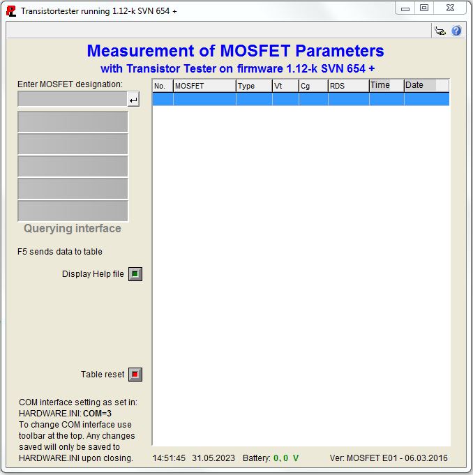
Softwareoberfläche zur Messung von MOSFET-Parametern
Transistortester running 1.12-k SVN 654 + Measurement of MOSFET Parameters with Transistor Tester on firmware 1.12-k SVN 654 + Enter MOSFET designation: No. MOSFET Type Vt Cg RDS Time Date Querying interface F5 sends data to table Display Help file Table reset
in „Transistortester AVR“ · Projekte & Code · · Screenshots
-
PDF
GL10N10B4S.pdf
R ○ GL10N10B4S 无锡光磊电子科技有限公司 GL Silicon N-Channel Power MOSFET General Description: VDSS 100 V The GL10N10B4S uses advanced trench technology and ID 10 A design to provide excellDS(ON)ith low gate charge. It PD 40 W R 110 mΩ can be used in a wide variety of applications
in „LED-Strip flackert, trotz 1.5kHz dimmfrequenz.“ · Mikrocontroller und Digitale Elektronik ·
-
PDF
2108182030_GL-GL10N10B4S_C2886410.pdf
R ○ GL10N10B4S 无锡光磊电子科技有限公司 GL Silicon N-Channel Power MOSFET General Description: VDSS 100 V The GL10N10B4S uses advanced trench technology and ID 10 A design to provide excellDS(ON)ith low gate charge. It PD 40 W R 110 mΩ can be used in a wide variety of applications
in „Betrieb von MOSFETS bei maximalstrom?“ · Analoge Elektronik und Schaltungstechnik ·
-
PDF
lm5163_DC-DC-3V3.pdf
30 Ω BOOTSTRAP V Gate drive UVLO V rising 2.7 3.4 V BST-UV BST POWER SWITCHES RDSON-HS High-side MOSFET R DSON SW = –100 mA 0.725 Ω RDSON-LS Low-side MOSFET R DSON SW = 100 mA 0.33 Ω Copyright © 2019, Texas Instruments Incorporated Submit Documentation Feedback 5 Product Folder Links: LM5163 LM5163 SNVSBB3
in „DC/DC Spannungsdrops während Bootvorgang uC“ · Analoge Elektronik und Schaltungstechnik ·
-
PDF
stepper_motor_ref_design_an155.pdf
the Power MOSFET. The resistor also protects the MCU small low on-resistance power MOSFETs in an SO8 from excessive currents and voltage transients. package. These MOSFETs were chosen for their 30 V rating, 3 V gate
in „Schrittmotorrampe für Konstante Beschleunigung“ · Mikrocontroller und Digitale Elektronik ·
-
PDF
max774-max776.pdf
to +70°C Dice* 7 switching regulators with on-board MOSFETs. MAX774EPA -40°C to +85°C 8 Plastic DIP 6 Applications MAX774ESA -40°C to +85°C 8 SO LCD-Bias Generators MAX774MJA -55°C to +125°C 8 CERDIP *Contact factory for dice specifications. High-Efficiency
in „[V] kleines Konvolut ältere DIL / DIP ICs (8€)“ · Markt ·
-
PDF
STR-W6253D_PWMswitschRegulator.pdf
Pin-out Diagram Terminal List Table Number Name Description Functions 1 D/ST Drain/startup terminal MOSFET drain and input of start-up signal 2 NC Clipped No connection Source/Overcurrent Protection MOSFET source and input of overcurrent 3 S/OCP terminal detection signal 4 VCC Power supply terminal Input
in „suche Diode aus Schaltnetzteil“ · Analoge Elektronik und Schaltungstechnik ·
-
PDF
STR-W6253D_PWMswitschRegulator.pdf
Pin-out Diagram Terminal List Table Number Name Description Functions 1 D/ST Drain/startup terminal MOSFET drain and input of start-up signal 2 NC Clipped No connection Source/Overcurrent Protection MOSFET source and input of overcurrent 3 S/OCP terminal detection signal 4 VCC Power supply terminal Input
in „Reparatur Audio-Schaltnetzteil“ · Analoge Elektronik und Schaltungstechnik ·
-
PDF
Microsemi_13.56_MHz__Class-D_Half_Bridge.pdf
Application Engineer Phone: 541-382-8028, ext. 1205 gchoi@microsemi.com INTRODUCTION The DRF1400 is a MOSFET Half Bridge (HB) Hybrid Device which has been optimized for efficiency and reduced system cost; it is targeted at the HF ISM market arena. The DRF1400 contains two gate drivers and two power MOSFETs
in „Bauplan für HF Netzteil gesucht.“ · HF, Funk und Felder ·
-
PDF
axpert_vm_iii5000__c.pdf
-5000 ALL of the MOSFET aMOSFET TOSHIBA/TK100E08N1 214A 80V N BULK TO-)20 Parts Attribute Reference values Failure status CSD19505KCS (VMIII-3200)Resistor GS: 11.75k Short or explosion TK100E08N1 (VMIII-5200) GD: 115.8k DS
in „PV Wechselrichter startet nicht mehr und verursacht Kurzschluss bzw. hohen Strom“ · Analoge Elektronik und Schaltungstechnik ·
-
PDF
tc4420.pdf
TC4420 TC4429 6A HIGH-SPEED MOSFET DRIVERS FEATURES GENERAL DESCRIPTION ■ Latch-Up Protected ............ Will Withstand >1.5A TheTC4420/4429are6A(peak),singleoutputMOSFET Reverse Output Current drivers. The TC4429 is an inverting driver
in „Mosfet Driver gesucht“ · Mikrocontroller und Digitale Elektronik ·