-
Datei
fonttab.h
/ f { 0x0C, 0x52, 0x52, 0x52, 0x3E }, // g { 0x7F, 0x08, 0x04, 0x04, 0x78 }, // h { 0x00, 0x44, 0x7D, 0x40, 0x00 }, // i { 0x20, 0x40, 0x44, 0x3D, 0x00 }, // j { 0x7F, 0x10, 0x28, 0x44, 0x00 }, // k { 0x00, 0x41, 0x7F, 0x40, 0x00 }, // l { 0x7C, 0x04, 0x18, 0x04, 0x78 }, // m { 0x7C, 0x08, 0x04, 0x04, 0x78 }, // n { 0x38, 0x44, 0x44, 0x44, 0x38 }, // o { 0x7C, 0x14, 0x14, 0x14, 0x08 }, // p { 0x08, 0x14, 0x14, 0x18, 0x7C }, // q { 0x7C, 0x08, 0x04, 0x04, 0x08 }, // r { 0x48, 0x54, 0x54, 0x54, 0x20 }, /
in „LED Dot-Matrix 5x7 Mäxle-Würfelspiel / 2er Würfel“ · Mikrocontroller und Digitale Elektronik ·
-
Datei
font_6x8.h
0x01, 0x02 }, // f { 0x00, 0x18, 0xA4, 0xA4, 0xA4, 0x7C }, // g { 0x00, 0x7F, 0x08, 0x04, 0x04, 0x78 }, // h { 0x00, 0x00, 0x44, 0x7D, 0x40, 0x00 }, // i { 0x00, 0x40, 0x80, 0x84, 0x7D, 0x00 }, // j { 0x00, 0x7F, 0x10, 0x28, 0x44, 0x00 }, // k { 0x00, 0x00, 0x41, 0x7F, 0x40, 0x00 }, // l { 0x00, 0x7C, 0x04, 0x18, 0x04, 0x78 }, // m { 0x00, 0x7C, 0x08, 0x04, 0x04, 0x78 }, // n { 0x00, 0x38, 0x44, 0x44, 0x44, 0x38 }, // o { 0x00, 0xFC, 0x24, 0x24, 0x24, 0x18 }, // p { 0x00, 0x18, 0x24, 0x24, 0x18, 0xFC }, // q { 0x00, 0x7C
in „Probleme mit dem LCD 4884 Shield“ · Mikrocontroller und Digitale Elektronik ·
-
PDF
vish_ILQ2.pdf
Semiconductors 1.4 ) 1.5 ( r Normalized to: e 1.3 t V = 10 V, I = 10 mA g TA= - 55 °C a TC= 25 °C F l 1.2 F A V T 1.0 d 1.1 A = 25 °C C CTR ce(satVCE = 0.4 V a e T = 70 °C w l A o 1.0 a NCTR - o 0.5 F0.9 N V T = 100 °C - A T NCTR(SAT) 0.8 C 0.0 0.0.1 1 10 100 0.1 1 10 100 iild1_05 IF- Forward Current
in „Optokoppler SPS 24V zu 5V“ · Mikrocontroller und Digitale Elektronik ·
-
PDF
MOC3023-M.pdf
. AmbientTemperature Fig. 4 LED Current Required toTrigger vs. LED PulseWidth 1.4 25 ) D ) 1.3 Z D L 20 NORMALIZED TO: Z A PWin≥ 100 µs L 1.2 M A O R ( O 1.1 F15 ( - F T - N T 1.0 R 10 N R R U R 0.9 C C E R G 5 E I G 0.8 R I T T 0 0.7 1 2 5 10 20 50 100 NORMALIZED TO T A = 25∞C LED TRIGGER WIDTH - PW
in „Moc3023 Tic225 Schaltung“ · Mikrocontroller und Digitale Elektronik ·
-
PDF
Diskrete_Fourier_Transformation.pdf
0.1 0.1 0.05 0.05 0 0 0 0.05 0.1 0.15 0.2 0.25 0 0.05 0.1 0.15 0.2 0.25 f/fa mit Phasenkorrektur ohne Phasenkorrektur 90 90 0.3 0.3 120 60 120 60 0.2 0.2 150 30 150 30 0.1 0.1 180 0 180 0 210 330 210 330 240 300
in „Schnelle FFT in Assembler“ · Digitale Signalverarbeitung / DSP / Machine Learning ·
-
PDF
Datenblatt_moc3022.pdf
. AmbientTemperature Fig. 4 LED Current Required toTrigger vs. LED PulseWidth 1.4 25 ) D ) 1.3 Z D L 20 NORMALIZED TO: Z A PWin≥ 100 µs L 1.2 M A O R ( O 1.1 F15 ( - F T - N T 1.0 R 10 N R R U R 0.9 C C E R G 5 E I G 0.8 R I T T 0 0.7 1 2 5 10 20 50 100 NORMALIZED TO T A = 25∞C LED TRIGGER WIDTH - PW
in „Phasenanschnitt- Fehler“ · Mikrocontroller und Digitale Elektronik ·
-
 Bild
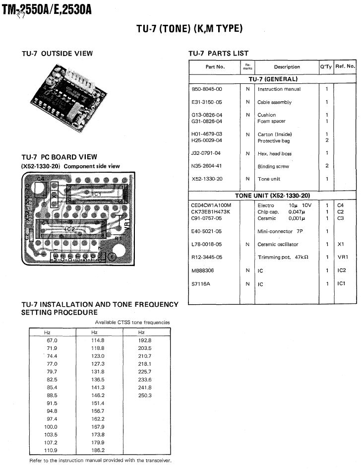
Technische Dokumentation TU-7 Tone Modul
TYPE) TU-7 OUTSIDE VIEW TU-7 PARTS LIST TU-7 (GENERAL) B50-8045-00 N Instruction manual 1 E31-3150-05 N Cable assembly 1 G13-0828-06 N Cushion 1 G31-0828-04 Foam spacer 1 H01-4679-03 N Carton (Inside) 1 H25-0029-04 Protective bag 2 J32-0791-04 N Hex, head boss 1 N35-2604-41 Binding screw 2 X52-1330-20
in „Subton CTCSS günstig nachrüsten“ · HF, Funk und Felder · · Screenshots
-
PDF
456-06183-0-LD1117D.pdf
0.019 0.023 D 6 6.2 0.236 0.244 E 6.4 6.6 0.252 0.260 G 4.4 4.6 0.173 0.181 H 9.35 10.1 0.368 0.397 L2 0.8 0.031 L4 0.6 1 0.023 0.039 0068772-B 18/23 LD1117 SERIES TO-220 MECHANICAL DAT A mm. inch DIM. MIN. TYP MAX. MIN. TYP. MAX. A 4.40 4.60 0.173 0.181 C 1.23 1.32 0.048 0.051 D 2.40 2.72 0.094 0.107
in „Von 9V auf 3-3,3V mit einem Spannungsregler“ · Analoge Elektronik und Schaltungstechnik ·
-
PDF
HY-LandTiger_SCH.pdf
ENETI_TXD1 DB02 DB02 ENET_TX_EN ENET_TX_EN DB03 DB03 ENET_CRS ENET_CRS DB04 DB04 ENET_RXD0 ENET_RXD0 DB05 DB05 ENET_RXD1 ENET_RXD1 DB06 DB06 ENET_RX_ER ENET_RX_ER DB07 DB07 ENET_REF_CLK ENET_REF_CLK LCD_CS LCD_CS ENET_MDC ENET_MDC LCD_RS LCD_RS ENET_MDIO ENET_MDIO LCD_WR LCD_WR RESET C LCD_RD LCD_RD C LCD_LE
-
Datei
Uhr_080209_mega328p.bas
Grafik sein 'End of Bitmap Zeichenbreite: Data &H04 , &H06 , &H09 , &H0F , &H0C , &H12 , &H0F , &H05 , &H08 , &H08, Data &H07 , &H0D , &H05 , &H09 , &H05 , &H08 , &H0B , &H09 , &H0B , &H0B, Data &H0C , &H0B , &H0B , &H0B , &H0B , &H0B , &H05 , &H05 , &H09 , &H0C, Data &H0C , &H0D , &H14 , &H0D , &H0C
in „ATMega328p mit S65 Display und Hard-SPI (Bascom)“ · Mikrocontroller und Digitale Elektronik ·
-
PDF
ROS-1700W.pdf
) Suggested Layout, Tolerance to be within±.002 inch Outline Dimensions ( mm ) A B C D E F G H J K L M N P Q R S T wt. .500 .500 .180 .100 .080 .115 .060 .040 .540 .060 .100 .135 .135 .115 .140 .070 .150 .070 grams 12.70 12.70 4.57 2.54 2.03 2.92 1.52 1.02 13.72 1.52 2.54 3.43 3.43 2.92 3.56 1.78 3.81
in „Frage zu VCO Daten“ · Analoge Elektronik und Schaltungstechnik ·
-
PDF
-_IC_LEXIKON_-_multimaster.pdf
78m05ct qkp616 LaNrNOS PosFRCkI HerSte PinBA Bezeich1 Bezeich2 Bezeich3 Bezeich4 202 k9 ? 2x4son pe-65848 9617-c china LaNrNOS PosFRCkI HerSte PinBA Bezeich1 Bezeich2 Bezeich3 Bezeich4 203 k9 motor 1x3son
in „(V) Bauelemente 70er-90er zu verkaufen Vintage Retro“ · Markt ·
-
PDF
HY1403-HOOYI.pdf
2.38 A2 0.97 1.07 1.17 b 0.72 0.78 0.85 b1 0.71 0.76 0.81 b3 5.23 5.33 5.46 c 0.47 0.53 0.58 c1 0.46 0.51 0.56 D 6.00 6.10 6.20 D1 5.30REF E 6.50 6.60 6.70 E1 4.70 4.83 4.92 e 2.286BSC H 16.10 16.40 16.60 L1 9.20 9.40 9.60 L3 0.90 1.02 1.25 L5 1.70 1.80 1.90 1 5° 7° 9° 2 5° 7° 9° K 0.40REF 9 www.hooyi.cc HY1403D/U/S TO-251-3L SYMBOL MM MIN NOM MAX A 2.20 2.30 2.38 A2 0.97 1.07 1.17 b 0.72 0.78 0.85 b1 0.71 0.76 0.81 b3 5.23 5.33 5.46 c 0.47
in „Alternative zu beschädigtem MOSFET?“ · Analoge Elektronik und Schaltungstechnik ·
-
PDF
LQ092B5DW02.pdf
720.00 809.22 907.21 57 692.12 779.34 875.36 58 665.50 750.76 844.84 59 640.07 723.42 815.58 60 615.78 697.25 787.53 61 592.57 672.20 760.63 62 570.39 648.21 734.81 63 549.18 625.24 710.05 64 528.89 603.22 686.28 65 509.49 582.12 663.45 66 490.92 561.90 641.54 67 473.14 542.51 620.49 68 456.13 523.91
in „Anschluss TFT-LCD-Modul SHARP LQ092B5DW02 vs. LQ092B5DW01“ · Mikrocontroller und Digitale Elektronik ·
-
PDF
BSS138.pdf
2.50 G TOP VIES Mechanical Data D 0.89 1.03 E G D E 0.45 0.60 · Case: SOT-23, Molded Plastic H G 1.78 2.05 · Case Material - UL Flammability Classification Rating 94V-0 K M H 2.80 3.00 J J · Moisture sensitivity: Level 1 per J-STD-020A L 0.013 0.10 · Terminals: Solderable per MIL-STD-202, Drain K 0.903
in „Logic Level Hype“ · Analoge Elektronik und Schaltungstechnik ·
-
PDF
502003-da-01-de-TEMPERATURMODUL_I2C_32_480_C.pdf
vom ASIC auf 5 V l h geregelt, die auch als digitale Bezugsspannung für Daten b die I C-Kommunikation dient. o 0x78 Byte_0 MSB PT1000 Temperature n Sondervarianten für 2,7 ... 5,5 V digitale Kommu- g nikation sind auf
in „Hygrosens I2C Tmp Modul antwortet nicht“ · Mikrocontroller und Digitale Elektronik ·
-
PDF
fdgfdkfdp.pdf
at on = 1.5 h; off 0.5 h room temperature 25 °C; 1000 h ± (3.0 % R + 0.05 ) 25 °C; 8000 h ± (6.0 % R + 0.05 ) Endurance at upper Ptest= Pcat= 0.54 x P70 4.25.3 - U test 0.54 x P 70x R U max. category temperature 200 °C; 1000 h ± (3.0 % R + 0.05 ) (40 ± 2) °C; 4.24 78 (Cab) Damp heat, 56 days; ± (0.5 % R + 0.05 ) steady state (93 ± 3) % RH Note (1)The quoted IEC standards are also released as EN standards with the same number and identical contents DIMENSION AND MASS L d B D S A L D (1) d B A S (2) MASS TYPE
-
PDF
STP6NK90ZFP.pdf
0.38 0.534 c2 1.19 1.34 D 8.60 9.00 D1 6.90 7.50 E 10.15 10.55 E1 8.10 8.70 e 2.54 BSC H 15.00 15.60 L 1.90 2.50 L1 1.65 L2 1.78 L3 0.25 L4 4.78 5.28 DS2985 - Rev 6 page 13/26 STB6NK90ZT4, STP6NK90Z, STP6NK90ZFP, STW7NK90Z D²PAK (TO-263) package information Figure 25. D²PAK (TO-263) recommended footprint
-
PDF
STP6NK90ZFP.pdf
0.38 0.534 c2 1.19 1.34 D 8.60 9.00 D1 6.90 7.50 E 10.15 10.55 E1 8.10 8.70 e 2.54 BSC H 15.00 15.60 L 1.90 2.50 L1 1.65 L2 1.78 L3 0.25 L4 4.78 5.28 DS2985 - Rev 6 page 13/26 STB6NK90ZT4, STP6NK90Z, STP6NK90ZFP, STW7NK90Z D²PAK (TO-263) package information Figure 25. D²PAK (TO-263) recommended footprint
in „Unterschiedliche Power MOSFET kompatibel?“ · Analoge Elektronik und Schaltungstechnik ·
-
PDF
IRFR2307Z.pdf
PD - 96910 AUTOMOTIVE MOSFET IRFR2307Z IRFU2307Z Features lAdvanced Process Technology ® HEXFET Power MOSFET lUltra Low On-Resistance l175°C Operating Temperature D V = 75V lFast Switching DSS lRepetitive Avalanche Allowed up to Tjmax R DS(on) = 16mΩ G Description
in „MOSFET IRFR2307Z“ · Analoge Elektronik und Schaltungstechnik ·
-
PDF
High_Voltage_R.pdf
VR68 Vishay BCcomponents High Ohmic (up to 68 MΩ)/ High Voltage (up to 10 kV) Resistors DIMENSIONS L1 Ø d Ø D L2 Outline DIMENSIONS - resistor type and relevant physical dimensions TYPE Ø D max. L1 max. L 2 max. Ø d VR68 6.8 18.0 19.0 0.78 ± 0.05 Yellow and grey are used instead of gold and silver because
in „Hochspannung mit RaspberryPi messen“ · Mikrocontroller und Digitale Elektronik ·
-
PDF
156503-as-01-de-UNIVERSAL_SCHALTMODUL_PLATINE_12V_DC_1_.pdf
Verfügung. Die Spannung ist stabilisiert und gemäß den I Spezifikationen des integrierten Spannungsreglers 78L05 kurzschlussfest. Die N E maximale Stromentnahme darf in Summe 10 mA nicht überschreiten. Anlegen O externer Spannung führt zur Beschädigung von Bauteilen! R Y H An Stift 4 steht die gleichgerichtete
in „Schalten bei definierten Strom“ · Analoge Elektronik und Schaltungstechnik ·
-
PDF
AV02-3563EN_DS_ACPL-C87x_04Mar2013.pdf
transistor because of the high-speed digital nature of the signals gate drive circuit using an inexpensive 78L05 three-ter- inside the isolation amplifier. A 100 pF bypass capacitor minal regulator. To help attenuate high frequency power (Cin) is also recommended at the input pins due to the supply noise or
in „Hochspannung galvanisch getrennt messen“ · Analoge Elektronik und Schaltungstechnik ·
-
Datei
TEST.LST
00000000 .debug_abbrev 00000000 l d .debug_line 00000000 .debug_line 00000000 l d .debug_str 00000000 .debug_str 00000000 l d *ABS* 00000000 .shstrtab 00000000 l d *ABS* 00000000 .symtab 00000000 l d *ABS* 00000000 .strtab 00000000 l
-
PDF
T1-1T-KK81.pdf
loss, 0.3dB typ. TypicalPerformanceData FREQUENCY INSERTION INPUT (MHz) LOSS R. LOSS (dB) (dB) inch 0.05 2.78 1.64 Outline Dimensions ( mm ) 0.08 1.18 4.39 0.20 0.52 9.45 A B C D E F G H J 0.50 0.38 16.31 .30 .27 .23 .010 .042 .020 .100 .05 .05 1.00 0.36 19.67 7.62 6.86 5.84 0.25 1.07 0.51 2.54 1.27 1.27
in „RF Transformer Problem“ · Mikrocontroller und Digitale Elektronik ·
-
PDF
23810294.pdf
on B25/85value ± 0.5; ± 1.0; ± 1.5 % (3) Operating temperature range at zero power - 55 to 125 °C L2 L D3 Maximum dissipation at 25 °C 100 mW 1 L3 T 90294 a Thermal time constant 5 s Dissipation factor 10 mW/K L1 L2 Ø D 1 Ø D 2 Ø D3 L3 T 45 ± 3 6 ± 1 3.7 8.5 4.1 16.8 0.8 Thermal gradient < 0.05
-
PDF
irf3708.pdf
Maximum Avalanche Energy and Waveforms Vs. Drain Current 6 www.irf.com IRF3708/3708S/3708L TO-220AB Package Outline Dimensions are shown in millimeters (inches) 10.54 (.415) 3.78 (.149) - B - 2.87 (.113) 10.29 (.405) 3.54 (.139) 4.69 (.185) 2.62 (.103) 4.20 (.165) 1.32 (.052) - A - 1.22 (.048
in „IRF3708 als Schalter“ · Mikrocontroller und Digitale Elektronik ·
-
PDF
MC14538B-D.PDF
ns/pF) L + 107 ns 10 − 125 250 t , t = (0.26 ns/pF) C + 82 ns 15 − 95 190 PLH PHL L Input Rise and Fall Times tr ft 5 − − 15 ms Reset 10 − − 5 15 − − 4 B Input 5 − 300 1.0 ms 10 − 1.2 0.1 15 − 0.4 0.05 A Input
in „Max. Pulsverlängerung mit CD4098“ · Mikrocontroller und Digitale Elektronik ·
-
PDF
WBDesign5.pdf
webench ® WEBENCH Design Report LM5022MM/NOPB : LM5022MM/NOPB 11V-16V to 60.00V @ 2.1A October 18, 2018 05:05:12 GMT-07:00 ® WEBENCH Design Name Manufacturer Part Number Properties Qty Price Footprint D1 SMC Diode Solutions SB20150TR VF@Io= 1.05 V 1 $0.19 VRRM= 150.0 V DO-201AD 166 mm 2 L1 Coilcraft SER2915H
in „Drehstrom Motor anfangstrom berechnen“ · Analoge Elektronik und Schaltungstechnik ·
-
PDF
TDA5051A_-_PowerLine.pdf
nF/X2 MOV 250 V (AC) 250 V (AC) 250 V (AC) 68 (2 W) 47 H low R 47 nF S +5 V 1 mH (63 V) 1 3 1N4006 78L05 2 7V5 470 F (1.3 W) 1N4006 47 H (16 V) 1 F (16 V) 100 F 47 nF (16 V) VDDD VDDAP VDDA +5 V DATA IN 3 11 13 1 10 nF DATA RX IN OUT 2 14 MICRO- CONTROLLER TDA5051A TX OUT CLKOUT 10 4 PD SA5.0A 15 7 8
in „Probleme mit PLC-Modem-Chip TDA5051“ · Haus & Smart Home ·
-
PDF
TDA5051A.pdf
nF/X2 MOV 250 V (AC) 250 V (AC) 250 V (AC) 68 (2 W) 47 H low R 47 nF S +5 V 1 mH (63 V) 1 3 1N4006 78L05 2 7V5 470 F (1.3 W) 1N4006 47 H (16 V) 1 F (16 V) 100 F 47 nF (16 V) VDDD VDDAP VDDA +5 V DATA IN 3 11 13 1 10 nF DATA RX IN OUT 2 14 MICRO- CONTROLLER TDA5051A TX OUT CLKOUT 10 4 PD SA5.0A 15 7 8
in „µC Kommunikation (Signale) über Gleichspannung modulieren“ · Mikrocontroller und Digitale Elektronik ·
-
Datei
NOKIA_TEST_1.asm
0x08,0x14,0x22,0x41 ; ASCII-Code 0x4B (75) = 'K' 20 DT 0x7F,0x40,0x40,0x40,0x40 ; ASCII-Code 0x4C (76) = 'L' DT 0x7F,0x02,0x06,0x02,0x7F ; ASCII-Code 0x4D (77) = 'M' DT 0x7F,0x06,0x08,0x30,0x7F ; ASCII-Code 0x4E (78) = 'N' DT 0x3E,0x41,0x41,0x41,0x3E ; ASCII-Code 0x4F (79) = 'O' DT 0x7F,0x09,0x09,0x09,0x06
in „Nokia 3310 Display mit PIC steuern“ · Mikrocontroller und Digitale Elektronik ·
-
PDF
THS4061-4062.PDF
SUPPLY VOLTAGE 90 30 B d 88 – V 25 t – a 86 g n VCC = –15 V i RL= 1 k i 84 S 20 c e j a RL= 150 R 82 o l V 15 p 80 u u t r u e 78 VCC = 15 V – 10 o ) P 76 P – O R V 5 S 74 P 72 –40 –20 0 20 40 60 80 100 0 〉 4 〉 6 〉 8 〉 10 〉 12 〉 14 〉 16 TA– Free-Air Temperature – ⋅C VCC – Supply Voltage – V Figure 16 Figure
in „Verstärker für DC bis hohe Frequenz“ · Analoge Elektronik und Schaltungstechnik ·
-
PDF
Halbwachs-Baessler78-2.pdf
Halbwachs & Bässler: Wachstumsverläufe von Ektomykorrhizapilzen 223 Moore D, GangeAC, Gange EG, Boddy L (2008): Fruit Bodies: Their Production and Develop- ment in Relation to Environment. In Boddy L, Frankland JC, Van West P: Ecology of Saprotrophic Basidiomycetes. Elsevier Academic Press: 79-103. Moser
in „Logger zur Registrierung von Distanzen“ · Digitale Signalverarbeitung / DSP / Machine Learning ·
-
PDF
batterien.pdf
100,725 0,36261 97 0,348 104,1096 RANDOM-AKKUS AccuCell AAA 2,10 1 10,5 44,5 11 750 1,5 1,00 15413,05 1125,0 1125,0 72,990 0,26276 102 0,368 5,3571 Sanyo AAA Ni-Mh 2,55 1 10,5 44 13 1000 1,2 1,00 15239,87 1200,0 1200,0 78,741 0,28347 92 0,332 4,7059 Sanyo 18650 10,95 1 18 70 48 2600 3,7 1,00 71251,32
in „Hier mal ein Batterievergleich und Bitte um Beratung bei Batterien“ · Mikrocontroller und Digitale Elektronik ·
-
PDF
RSZ.pdf
E-77 RSZ/P ECONOLINE DC/DC-Converter 1 Series 0 . Typical Characteristics c e D RSZ-xx3.3/P RSZ-xx05/P E I Efficiency / Load Efficiency / Load L 100 100 F 2405 80 80 O 243.3 1205 D 60 60 N 40 E % 40 % 0505 n 20 123.3 n 20 i 053.3 f E 0 E 0 0% 20% 40% 60% 80% 100% 0% 20% 40% 60% 80% 100% Total Output
-
PDF
traco_Netzteil_datasheet.pdf
24 VDC 5.0 A TXL 120-48S 48 VDC 2.5 A TXL 15 0-05S 5 VDC 30.0 A TXL 15 0-12S L 15 0 Watt 12 VDC 12.5 A TXL 15 0-24S 24 VDC 6.3 A TXL 15 0-48S 48 VDC 3.2 A TXL 220-12S 12 VDC 18.4 A TXL 220-24S N 220 Watt 24 VDC 9.2 A TXL 220-48S 48 VDC 4.6 A TXL 300
in „SNT mit mehreren Spannungen - gemeinsame Masse?“ · Analoge Elektronik und Schaltungstechnik ·
-
PDF
CP1_20201222.pdf
P 5 F FH JKB P 5 F F H JKB P 5 F FH JKB P 5 F F H JKB P 5 FF H JKB P 5 F F H KB P 5 FF H JKB B B/1 L/7 V/CLR K P14B05 G1G1 G2 K PI1405 G1 G1 G2 K P14B0 G1G1 G2 K P14405 G1 G1 G2 K P14B05G1 G1 G2 K P14605 G1 G1 G2 K P14B0 G1 G1 G2 K P14B05 G1 G1G2 K PI14B5 G1 G1 G2 K P14005 G1 G1 G2 PI31 PS0 PI41 PI42
in „Lerncomputer so wie KOSMOS CP1 nachbauen“ · Mikrocontroller und Digitale Elektronik ·
-
PDF
715G6677-P02-001-0020_PSU.pdf
Sepdiv.table Circuit Diagrams and PWB Layouts QM15.2E LA 10. EN 74 10-4-3 Standby Standby U9303 12VS L9302 HOT COLD NC/AS78L12RTR-G1 3UH HV Q9304 NC/P1604ED A03 C9332 3 +12V A03 4 R9322 + FB9301 ! T9301 7 I 2 1 R GND NC/100KOHM 1/8W C9326 1 2 P5WER X'FMR 100NU9302 SYNC 4 3 470uF 25V R9320 W 2 T + + +
in „Frage an die Experten“ · Analoge Elektronik und Schaltungstechnik ·
-
PDF
philips_715g6677-p02_psu.pdf
Sepdiv.table Circuit Diagrams and PWB Layouts QM15.2E LA 10. EN 74 10-4-3 Standby Standby U9303 12VS L9302 HOT COLD NC/AS78L12RTR-G1 3UH HV Q9304 NC/P1604ED A03 C9332 3 +12V A03 4 R9322 + FB9301 ! T9301 7 I 2 1 R GND NC/100KOHM 1/8W C9326 1 2 P5WER X'FMR 100NU9302 SYNC 4 3 470uF 25V R9320 W 2 T + + +
in „TV Netzteil defekt (Philips LCD TV 40 PUK 6400/12 )“ · Analoge Elektronik und Schaltungstechnik ·
-
Datei
char.h
/ f { 0x0C, 0x52, 0x52, 0x52, 0x3E }, // g { 0x7F, 0x08, 0x04, 0x04, 0x78 }, // h { 0x00, 0x44, 0x7D, 0x40, 0x00 }, // i { 0x20, 0x40, 0x44, 0x3D, 0x00 }, // j { 0x7F, 0x10, 0x28, 0x44, 0x00 }, // k { 0x00, 0x41, 0x7F, 0x40, 0x00 }, // l { 0x7C, 0x04, 0x18, 0x04, 0x78 }, /
in „Zeichensatz für SED1520“ · Mikrocontroller und Digitale Elektronik ·
-
Datei
char.h
/ f { 0x0C, 0x52, 0x52, 0x52, 0x3E }, // g { 0x7F, 0x08, 0x04, 0x04, 0x78 }, // h { 0x00, 0x44, 0x7D, 0x40, 0x00 }, // i { 0x20, 0x40, 0x44, 0x3D, 0x00 }, // j { 0x7F, 0x10, 0x28, 0x44, 0x00 }, // k { 0x00, 0x41, 0x7F, 0x40, 0x00 }, // l { 0x7C, 0x04, 0x18, 0x04, 0x78 }, /
in „Die Welt der LCD-Grafik-Displays“ · Mikrocontroller und Digitale Elektronik ·
-
PDF
STM.pdf
0.020 B 0.77 1.65 0.030 0.065 b 0.5 0.020 b1 0.25 0.010 D 20 0.787 E 8.5 0.335 e 2.54 0.100 e3 17.78 0.700 F 7.1 0.280 I 5.1 0.201 L 3.3 0.130 Z 1.27 0.050 P001C 9/13 M54/M74HC165 Ceramic DIP16/1 MECHANICAL DATA mm inch DIM. MIN. TYP. MAX. MIN. TYP. MAX. A 20 0.787 B 7 0.276 D 3.3 0.130 E 0.38 0.015 e3 17.78 0.700 F 2.29 2.79 0.090 0.110 G 0.4 0.55 0.016 0.022 H 1.17 1.52 0.046 0.060 L 0.22 0.31 0.009 0.012 M 0.51 1.27 0.020 0.050 N 10.3 0.406 P 7.8 8.05 0.307 0.317 Q 5.08 0.200 P053D 10/13 M54/M74HC165
in „Arduino + 74HC165“ · Mikrocontroller und Digitale Elektronik ·
-
Datei
lab9.sx.txt
;$189C $7B $10 $06 beq L18A6 ;$189F $27 $05 cmpb #$03 ;$18A1 $C1 $03 beq L18B0 ;$18A3 $27 $0B rts ;$18A5 $3D L18A6 brclr L008B,$01,L18A6 ;$18A6 $4F $8B $01 $FC ldd L0090 ;$18AA $DC $90 std L1002 ;$18AC $7C $10 $02 rts ;$18AF
in „HCS12 CPU Disassembler“ · Mikrocontroller und Digitale Elektronik ·
-
PDF
LT1082.pdf
CURRENT ( A) DUTY CYCLE (%) TEMPERATURE (°C) 1082 G03 1082 G04 1082 G05 Flyback Blanking Time MinimumInput Voltage Switch Saturation Voltage 2.2 2.9 2.00 V1.75 2.0 ( 2.8 SW = 1A E TJ= 150°C E A1.50 1.8 A 2.7 L TJ= 100°C L V T = 25°C s V SW = 0A N1.25 J ( 1.6 U 2.6 T M P
in „Boost Converter 2MHz 50V“ · Mikrocontroller und Digitale Elektronik ·
-
Datei
hwinfop14s.txt
=1 E: MEI_CL_UUID=309dcde8-ccb1-4062-8f78-600115a34327 E: MEI_CL_NAME= E: MODALIAS=mei::309dcde8-ccb1-4062-8f78-600115a34327:01: P: /devices/pci0000:00/0000:00:16.0/0000:00:16.0-3c4852d6-d47b-4f46-b05e-b5edc1aa440e M: 0000:00:16.0-3c4852d6-d47b
in „Lenovo Thinkpad P14s (Intel) freeze beim Steckerziehen“ · PC Hard- und Software ·
-
Datei
Lite08.asm
clock_ne555 .def keyaux = r03 ;aux03:aux_keys .def keyfbck = r04 ;aux04:function+bck_keys .def swbcd01 = r05 ;aux05:switch_bcd0+1 .def swbcd23 = r06 ;aux06:switch_bcd2+3 .def aux07 = r07 ;aux07: .def aux08 = r08 ;aux08: .def aux09 = r09 ;aux09: .def aux10 = r10 ;aux10: .def aux11 = r11 ;aux11: .def aux12 =
in „Der STACK - Unterprogramme mit variabler Parameteranzahl“ · Projekte & Code ·
-
Datei
Lite08.asm
clock_ne555 .def keyaux = r03 ;aux03:aux_keys .def keyfbck = r04 ;aux04:function+bck_keys .def swbcd01 = r05 ;aux05:switch_bcd0+1 .def swbcd23 = r06 ;aux06:switch_bcd2+3 .def aux07 = r07 ;aux07: .def aux08 = r08 ;aux08: .def aux09 = r09 ;aux09: .def aux10 = r10 ;aux10: .def aux11 = r11 ;aux11: .def aux12 =
in „meinungen zu ass.prog.“ · Mikrocontroller und Digitale Elektronik ·
-
Datei
Lite08.asm
clock_ne555 .def keyaux = r03 ;aux03:aux_keys .def keyfbck = r04 ;aux04:function+bck_keys .def swbcd01 = r05 ;aux05:switch_bcd0+1 .def swbcd23 = r06 ;aux06:switch_bcd2+3 .def aux07 = r07 ;aux07: .def aux08 = r08 ;aux08: .def aux09 = r09 ;aux09: .def aux10 = r10 ;aux10: .def aux11 = r11 ;aux11: .def aux12 =
in „Problem bei Tasterabfrage“ · Mikrocontroller und Digitale Elektronik ·
-
PDF
NT7533Lcd.pdf
interface 30 C86 I C86 = ”L”: 8080 series MPU interface When P/S = “L”(serial or IIC mode) : C86 should be connected to VDD1 or VSS1. This is the chip select signal. When /CS = “L”, then the chip select 40 /CS I becomes active,
in „Seriell (4-Wire)-LCD-Ansteuerung mit NT7533“ · Mikrocontroller und Digitale Elektronik ·