-
Datei
MCP2510Report.htm
="#0000A0"><strong><em><font face="Verdana" size="2" color="#FFFFFF">Configuration Register Setup (PIC18/MCP251X) (neoVI blue/green, ValueCAN 2) </font></em></strong></td> </tr> </table> <table border="0" width="100%"> <tr> <td width="33%" bgcolor="#000000"><font face="Verdana" size="2" color="#FFFFFF
in „PIC18F2680 CAN Baudrate auf 16 kbs setzen ?“ · Mikrocontroller und Digitale Elektronik ·
-
 Bild
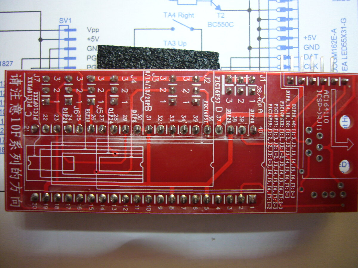
Rote Leiterplatte mit Schaltplan im Hintergrund
Right T2 BC550C TA3 Up J7 3 2 1 J6 25 D210 22 1 J5 27 D214 29 1 J4 31 D218 32 1 J3 33 1 J2 34 1 J1 37 PIC16F57 D216 40 1 39 38 3 2 1 28-pin PIC16F57 D174 bis D177 110 ICSP J11 1 2 3 4 5 6 7 8 9 10 11 12 13 14 15 16 17 18 19 20 请注意10系列的方向
in „PIC Programmieren“ · Mikrocontroller und Digitale Elektronik · · Platinenfotos
-
 Bild
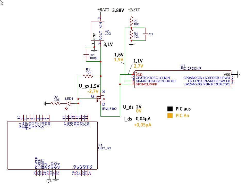
Schaltplan mit PIC12F683 und Arduino Uno R3
+BATT 3,88V, R3 10k, R4 10k, C1, U2 LDO, VOUT 3,1V, GND, C2 100pF, R1 10k, U_gs 1,5V, S, G, D, IRML6402, U_ds 2V, 0V, I_ds -0,04µA, +0,05µA, PIC An, PIC aus, LED1 bis LED8, R2 220, P1 UNO_R3, SCL, SDA, AREF, GND, D13, D11, D10, D9, D8, D7, D6, D5, D4, D3, D2, D1, D0, 10, 9, 8, 7, 6, 5, 4, 3, 2, 1, 18, 17, 16, 15, 14, 13, 12, 11, 10, 25, 26, 27, 28, 29, 30, 31, 32, POWER, RESET, 5V, 3V3, GND, GND, VIN, A0, A1, A2, A3, A4, A5, -5V
in „Mit Attiny85 einen PIC Mikrokontroller ausschalten“ · Analoge Elektronik und Schaltungstechnik · · Schaltpläne
-
Datei
CAN_RS232.asm
Processor 18F258 include p18F258.inc CONFIG OSC = HS CONFIG WDT = OFF TEMP1 equ 0x00 ;Temp-Register FF equ 0x0c ;ASCII Form Feed CR equ 0x0d ;ASCII Carriage Return LF equ 0x0a ;ASCII Line Feed BS equ 0x08 ;ASCII
in „PIC18F258 sendet kein CAN-Telegramm“ · Mikrocontroller und Digitale Elektronik ·
-
Datei
YigFilter.asm
$08,$1C,0 ; 1 .db $1C,$22,$20,$10,$08,$04,$3E,0 ; 2 .db $3E,$10,$08,$10,$20,$22,$1C,0 ; 3 .db $10,$18,$14,$12,$3E,$10,$10,0 ; 4 .db $3E,$02,$1E,$20,$20,$22,$1C,0 ; 5 .db $18,$04,$02,$1E,$22,$22,$1C,0 ; 6 .db $3E,$20,$10,$08,$04,$04,$04,0 ; 7 .db $1C,$22,$22,$1C,$22,$22,$1C,0 ; 8 .db $1C,$22,$22,$3C,$20
in „Grafik LCD als text Display nutzen“ · Mikrocontroller und Digitale Elektronik ·
-
PDF
8-bit-MCU-Overview.pdf
D u S S C P C e T oT i C x M v u l l i P P S E S S I A A C A D O T I R Z ( 8 1 Q W W ( W R 8 1 1 C M C C P B W F U U 2I S I S Q Q w L E D E M S S p ATtiny102/104 8/14 1 0.032 1.8–5.5 12 10 5/8 2 2 1 4 ATtiny20x/40x/80x/160x 8–24 2–16 Up to 1 1.8–5.5 20 10 12
in „Moderne AVR (Nachfolger Atmega und Attiny)“ · Mikrocontroller und Digitale Elektronik ·
-
PDF
8-bit-MCU-Overview.pdf
D u S S C P C e T oT i C x M v u l l i P P S E S S I A A C A D O T I R Z ( 8 1 Q W W ( W R 8 1 1 C M C C P B W F U U 2I S I S Q Q w L E D E M S S p ATtiny102/104 8/14 1 0.032 1.8–5.5 12 10 5/8 2 2 1 4 ATtiny20x/40x/80x/160x 8–24 2–16 Up to 1 1.8–5.5 20 10 12
in „AVR®DD family, low pin count devices“ · Mikrocontroller und Digitale Elektronik ·
-
Datei
sdtest.c
// -*- tab-width: 4 -*- // SD Card Read Test // For use on dsPIC30F4013 at 3.3VDC // // Copyright (c) 2005, K9spud LLC. // http://www.k9spud.com/sdcard/ // // This program is free software; you can redistribute it and/or // modify it under the terms of the GNU General
in „Auslesen einer SD-Karte mit AVR“ · Mikrocontroller und Digitale Elektronik ·
-
Datei
rfm12_.c
/****************************************************************************** RFM12 für PIC C18 (18F2620) HoWL 11/2011 senden: polling empfangen: interrupt generelles Protokoll: [0] Anzahl der NUTZBytes [n] Nutzbytes [n+1] Prüfsumme HIGH [n+2] Prüfsumme LOW Daten senden: tx_daten[0] = 3; /
in „RFM12 Statusabfrage“ · Mikrocontroller und Digitale Elektronik ·
-
PDF
AN1154_Precision_Temperature_Sensing_with_RTD_Circuits.pdf
implemented using a 16-bit the RTD resistance varies due to temperature, tBIAS microcontroller such as PIC18F family. (biasing current) varies and temperature resolution remains below 0.01°C/LSb as shown in Figure 3. EQUATION 3: VOLTAGE ACROSS RTD V = V ⎛------------=-V--------------- 0.01 RTD REF⎝R A R
in „PT100 Zehntel Grad Auflösung“ · Analoge Elektronik und Schaltungstechnik ·
-
PDF
STM_DEV.pdf
PISS40113 PISS50113 PIUC1028 VDD_4 VSS_5 PIUC1010 PC7 PISS6014 PD2 PISS40114 PISS50114 PIUC1011 VDD_5 PC8 PISS6015 PD3 PISS40115 PISS50115 PC9 PISS6016 PD4 PISS40116 PISS50116 PIUC1022 PIUC1019 VCC VCC VDDA VSSA GND SS66 SS4 SS55 D STM32F103VE I2 I02 P02 P02 P2 P02 92 D COCK COCK COCK COCK COCK OCK OCK9
in „STM32 Development Board“ · Mikrocontroller und Digitale Elektronik ·
-
PDF
Schematic_Scope_1014D_2023-01-06.pdf
2 1 2 R152 TRG_RNG_B 5PF0-OSCIN BOOT0 44 10K CH2_RNG_A 6PF1-OSCOUT PB7 43 MATRIX_1A MATRIX_3A S19 S18 S17 S16 S15 S14 7NRST PB6 42 MATRIX_2A F1 F2 MODE EDGE CHX 50% 8VSSA PB5 41 9VDDA PB4 40 MATRIX_3A 1 2 1 2 1 2 1 2 1 2 1 2 R153 10 39 MATRIX_4A 10K CH2_POS_B 11 PA0 PB3 38 MATRIX_5A MATRIX_4A CH2_POS_A
in „Fnirsi 1014d defekt“ · Mikrocontroller und Digitale Elektronik ·
-
Datei
ea_dip204-4.h
// file ea-dip204-4.h // IN SERIAL MODE // creator Kees Neele // date 23-02-2014 // tested on PIC18F2550 at 16mHz // MPlabX 1.95 // Hi-Tech pro v9.80 #define u8 unsigned char #define s8 signed char #define u16 unsigned int #define s16 signed int #define u24 unsigned short long #define s24 signed
in „Display DIP204-4“ · Mikrocontroller und Digitale Elektronik ·
-
PDF
ErklearungDriverSimulation.pdf
12 1 TC 231U -103N C30 30 0 1n * HL Circuit G31 0 31 TABLE { V(3, 4) } ((0,130)(4.00,47.0)(6.00,28.8)(10.0,19.1)(13.0,17.3)(16.0,18.5)) R31 31 0 1 TC 3.72M 18.4U G33 0 30 TABLE { V(31, 30) } ( (-1M,-10)(0,0)(1,10N) ) S31 31 30 31 30 SS31 * LH Circuit G32 32 0 TABLE { V(3, 4) } ((0,150)(4.00,45.0)(6.00,27.6
in „Spice Simulation von Treiber TC4229“ · Analoge Elektronik und Schaltungstechnik ·
-
Datei
pic16f688HD44780graphics.c
#device PIC16F688, ADC=8 // Spectrum Analyzer & Scope Aug, 2008 #fuses hs,mclr,put,noprotect,nocpd,nobrownout,nowdt,nofcmen,noieso // nothing special needed here #use delay(clock=20000000) // compilerspecific delays
-
PDF
STM32H7-Disco_full.PDF
Comp GND PI1 P P3 PU6Ilim PI89 OC C3 R38 R39 GND 1P81SS FB PI52PI5 PR02PR0 PI21.0uF P7.5k P360R P1 P1 P1 17 Gnd 2 2 2 R41 R42 C36 P81Gnd_Therm P3 150nF 820R P51k P20k P222nF L7987 C37 GND P +14.8V_bat +14.8V 2 2 2 P3820pF R43 SW1 0 1 2 P2k4 J18 2 PW0 2 PI8 1 2 PJ8 4S0 3 P2 Fuseclip
in „STM32H7-Disco erster Test“ · Mikrocontroller und Digitale Elektronik ·
-
PDF
test_40pin.pdf
/T1OSI TX/RC6 25 17 RC2/CCP1 SDO/RC5 24 18 RC3/SCK SDI/RC4 23 19 RD0/PSP0 RD3/PSP3 22 20 RD1/PSP1 RD2/PSP2 21 VSS 1 2 3 1 PIC16F877P 4 1 9 8 7 6 5 4 3 2 1 1 9 8 7 6 5 4 3 2 1 C 1 6 V C 100nF V V + F S S n Port E Port E 1C0nF1 1 9 8 7 6 5 4 3 2 1 1 9 8 7 6 5 4 3 2 1 1 9 8 7 6 5 4 3 2 1 1 9 8 7 6 5 4 3 2 1 S2 1 5 4 1 S S S S IN OUT 1 Port C Port C Port D Port D GND 2 3 D ü +C1 C2 IC2 +C3 1 L g X1 1 7805 2 3 100µF 100nF 20µF 3 2 B1 2 k 5V-IN R 1 GND
in „PIC Assemblerprogramm- Problem“ · Mikrocontroller und Digitale Elektronik ·
-
Datei
GLCD.h
define R2 0x02 #define R3 0x03 #define R4 0x04 #define R5 0x05 #define R6 0x06 #define R7 0x07 #define R8 0x08 #define R9 0x09 #define R10 0x0A #define R12 0x0C #define R13 0x0D #define R14 0x0E #define R15 0x0F #define R16 0x10 #define R17 0x11 #define R18 0x12 #define R19 0x13 #define R20 0x14 #define
in „STM32 24Bit Bmp nach 565RGB Format“ · Mikrocontroller und Digitale Elektronik ·
-
Datei
Interrupts.h
*********************************** * FileName: GenProcs.c * Dependencies: GenProcs.h * Processor: PIC18F4685 * Complier: Microchip C18 * * * Author Date Comment *~~~~~~~~~~~~~~~~~~~~~~~~~~~~~~~~~~~~~~~~~~~~~~~~~~~~~~~~~~~~~~~~~~~~ * Stephan Krause 17/8/12 Version 1.0 - Initial Release **************
in „Array beschreiben schlägt fehl“ · Mikrocontroller und Digitale Elektronik ·
-
PDF
CAN_Bit_Timing.pdf
equation: be lengthened or PS2 can be shortened by resyncroni- 1 zation. PS1 is programmable from 1 - 8TQ and PS2 is NBR = f bit= -tbit programmable from 2 - 8TQ. FIGURE 1: CAN BIT TIME SEGMENTS SyncSeg PropSeg PhaseSeg1 (PS1) PhaseSeg2 (PS2) Sample Point Nominal Bit Time (NBT), t bit 2001 Microchip
in „Infos zum CAN Bit-Timing gesucht“ · Mikrocontroller und Digitale Elektronik ·
-
Datei
Daten.h
*********************************** * FileName: GenProcs.c * Dependencies: GenProcs.h * Processor: PIC18F4685 * Complier: Microchip C18 * * * Author Date Comment *~~~~~~~~~~~~~~~~~~~~~~~~~~~~~~~~~~~~~~~~~~~~~~~~~~~~~~~~~~~~~~~~~~~~ * Stephan Krause 17/8/12 Version 1.0 - Initial Release **************
in „Array beschreiben schlägt fehl“ · Mikrocontroller und Digitale Elektronik ·
-
PDF
ppt_schematic.pdf
R22 .1uF 10k J2 21 3 Debug PIC16F873 4 RJ11 1 28 C16 5 Port 2MCLR RB7 27 .1uF 6 3RA0 RB626 4RA2 RB425 5RA3 RB324 R7 6RA4 RB223 47k 8RA5 RB121 9Vss RB020 5v 10OSC2 Vss 19 +V 11RC0 RC718 12RC1 RC617 U3 14RC2 RC515 C18 78M05 RC3 RC4 .1uF U8 1IN OUT3 U5 C20 J1 1 MAX232 16 .1uF COM XTAL1 2V++ Gnd15 5 9 2 3C1- T1o14 4 8 Serial 10uF 1uF R9 20Mhz C22 4C2+ R1i13 2 7 Port 10k C5 C6 .1uF 6C2- R1o11 1 6 20pF20pF 7V- T1i10 C19
in „solar laderegler“ · Platinen ·
-
PDF
LPD6803.pdf
is 4.5v---8v when VCC>5V, 5V stable voltage output, when VCC<5V, VOUT=VCC, can be used as 14 VOUT inside working voltage, suggest outside contact a 0.01uF----0.1uF capacity 9 GND Ground Function Block: 2 LPD6803
in „SAMMELBESTELLUNG 3: LED-Streifen und Alu-Profile“ · Markt ·
-
PDF
LPD6803-1.pdf
is 4.5v---8v when VCC>5V, 5V stable voltage output, when VCC<5V, VOUT=VCC, can be used as 14 VOUT inside working voltage, suggest outside contact a 0.01uF----0.1uF capacity 9 GND Ground Function Block: 2 LPD6803
in „Datenblatt für IC: LPD6803 (Nur chinesisch?)“ · Mikrocontroller und Digitale Elektronik ·
-
PDF
25040.pdf
17 18 19 20 21 22 23 SCK Instruction Lower Address Byte 0 0 0 0 A8 0 1 1 A7 6 5 4 3 2 1 A0 Don’t Care SI Data Out High-impedance SO 7 6 5 4 3 2 1 0 FIGURE 3-2: BYTE WRITE SEQUENCE CS TWC 0 1 2 3 4 5 6 7 8
in „Eeprom Philip Pines Auslesen mit CH341“ · Fahrzeugelektronik ·
-
PDF
MCP73871-Data-Sheet-20002090E__2_.pdf
MCP73871 Typical Application AC-DC Adapter or USB Port 18, 19 1, 20 System IN OUT Load 10 μF 2 4.7 μF VPCC 14, 15, 16 470 VBAT 6 4.7 μF PG NTC 470 7 STAT2 THERM 5 470 8 10 k STAT1 PROG1 R Single-Cell LBO 13 PROG1 Li-Ion Battery 3 SEL Low Hi 4 12 R PROG3
in „Fehlersuche beim MCP73871“ · Mikrocontroller und Digitale Elektronik ·
-
Datei
Ethernet1.asm
LIST P=18F2455 w equ 1 f equ 0 CS equ 2 sclk equ 1 sdo equ 7 sdi equ 0 org 0x020 CHECKSUMCOUNT res 1 CHECKSUM res 3 ZAEHLERB res 1 BUFFER res 1 ETXST res 2 ETXND res 2 COUNT res 1 ;****************************
in „ENC28J60 PC reagiert nicht“ · Mikrocontroller und Digitale Elektronik ·
-
Datei
PIC_41__2-06_.asm
; Programm LCDEXP0.asm: Demoprogramm für LCD-Modul, angesteuert über Expander PCF8574 ; PIC 16F84, f = 4 MHz, SC = 1us; OUT(sda) an RA0, CLOCK(scl) an RA1, CS an RA2 ; Dieter Kohtz, Juni 2005 ;********************************************************************************************* LIST P = 16F84 ; legt den PIC-Controllertyp fest ; Configuration Bits (aus dem Header File P16F84.inc) _CP_ON EQU H'000F' _CP_OFF EQU H'3FFF' _PWRTE_ON EQU H'3FF7' _PWRTE_OFF EQU H'3FFF' _WDT_ON EQU H'3FFF' _WDT_OFF
in „LCD am I2C initialisieren“ · Mikrocontroller und Digitale Elektronik ·
-
PDF
Datasheet_MIC2875.pdf
Audio Applications • Portable Equipment Package Type MIC2875 (FIXEDO UTPUT) MIC2875 (A DJ. UTPUT ) 8-Pin 2x2 TDFN* (MT) 8-Pin 2x2 TDFN* (MT) (Top View) (Top View) SW 1 ▲ 8 OUT SW 1 ▲ 8 OUT PGND 2 7 /PG PGND 2 7 /PG 3 EP EN 3 EP EN IN 6 IN 6 AGND 4 5 OUTS AGND 4 5 FB * Includes exposed thermal pad (EP
in „MI2875 PG-PIN“ · Analoge Elektronik und Schaltungstechnik ·
-
PDF
MIC5233-3.3YS-microchip-20221000.pdf
Batteries MIC5233YM5 • Automotive Electronics 1 5 VIN VOUT • Battery-Powered Systems 2 R1 C = 2.2 μF • 3-4 Cell Li-Ion Battery Input Range CIN 1.0 μF CERAMIC 3 4 OFF ON EN R2 GND= 18 μA Package Types MIC5233 MIC5233 5-Pin SOT23 3-Pin SOT223 (Top View) (Top View) EN GND IN 3 2 1 GND 4 L3xx 4 5 1 2 3
in „STM32F302C8T6 Schaltplanüberprüfung“ · Mikrocontroller und Digitale Elektronik ·
-
PDF
MSP-EXP430G2_LaunchPad_de.pdf
s C21 R29 XIN 2 P1.0 2 19 XINR XIN 19 In 12pF 0R 3 P1.1 3 18 XOUTR XOUT 18 E str 4 P1.2 4 17 TEST/SBWTCK 17 u DNP ARZ 6 P1.4 6 15 P1.7SBWTDIO 15 X m 5 DNP 7 P1.5 7 14 P1.6 14 P en Q2 GND 8 P2.0 8 13 P2.5 13 ts DNP R28 9 P2.1 9 12 P2.4 12 43 C22
in „gutes Übersetzungsprogramm für Datenblätter gesucht“ · Offtopic ·
-
Datei
usb_cdc.c
tfischl@gmx.de> 2013, Jürgen Liegner <juergen@liegner.de> expand bulk send buffer to 0x40 bytes Device: PIC18F14K50 Compiler: HI-TECH C PRO for the PIC18 MCU Family (Lite) V9.65 License: This file is open source. You can use it or parts of it in own open source projects. For closed or commercial projects
in „Fertiggerät: CAN <-> USB Wandler“ · Mikrocontroller und Digitale Elektronik ·
-
PDF
MCP6V11U_OpAmp.pdf
1.6V to 5.5V, V = GND, V = V /3, V = V /2, A DD SS CM DD OUT DD V = V /2, R = 100 kΩ to V and C = 20 pF. L DD L L L 8 45% VDD= 1.6V 21 Samples 6 Representative Part s0% TA= +25°C V c ( 4 e5% e r a 2 c0% o 25% V 0 f e 20% f-2 g O -40°C t5% u-4 +25°C e n +85°C r0% I-6 +125°C P 5% -8 0% -0.5 0.0 0.5 1.0 1.5
in „OpAmps: Maximale Widerstandswerte“ · Analoge Elektronik und Schaltungstechnik ·
-
PDF
0A1E438Cd01_batterypower_appnote.PDF
Range Packages MCP1630 3.0-5.5 12 nS typ. Cycle-by-Cycle Peak Current Control1.0 MHz -40°C to +125°C 8-pin MSOP Selected Product Specifications: PIC12F683 Microcontroller Device Bytes OTP/Flash RAM I/O 8-bit ADC Comparators Timers/ Max. Other Features Packages Words Bytes Pins Channels WDT Speed MHz PIC12F683
in „mit Akku Microcontroller versorgen, 3,6V auf 5V“ · Mikrocontroller und Digitale Elektronik ·
-
Datei
MPLAYER.ASM
in al,dx in al,dx in al,dx xor al,PAR_CTRL_STROBE out dx,al loop adh_digitloop mov al,[line] or al,0f8h mov dx,bp add dx,PAR_DATA out dx,al mov dx,bp add dx,PAR_CONTROL in al,dx xor al,PAR_CTRL_SEL out dx,al xor al,PAR_CTRL_SEL out dx,al mov ax,[DisplayIRQ] cmp ax,7 jbe adh_firstpiconly mov dx,SLAVE_PIC
in „Kennt sich jemand mit Tastatur Puffern aus ?“ · Mikrocontroller und Digitale Elektronik ·
-
PDF
ps2.pdf
0x43 0xc3 M 0x32 0xb2 F10 0x44 0xc4 N 0x31 0xb1 F11 0x57 0xd7 O 0x18 0x98 F12 0x58 0xd8 P 0x19 0x99 PRNT SCRN 0xe0, 0x2a, 0xe0, 0xb7 0xe0, 0x37, 0xe0, 0xaa Q 0x10 0x19 SCROLL 0x46 0xc6 R 0x13 0x93 PAUSE 0xe1, 0x1d, 0x45, -none
in „Unbekannter 2-Draht Bus - Event Triggered“ · Mikrocontroller und Digitale Elektronik ·
-
Datei
tastertolcd.asm
; This file is a basic code template for assembly code generation * ; on the PIC16F628A. This file contains the basic code * ; building blocks to build upon. * ; * ; If interrupts are not used all code presented between the ORG * ; 0x004 directive and the label main can be removed
in „Quarz auf Funktionalität testen?“ · Mikrocontroller und Digitale Elektronik ·
-
Datei
MCP795XX.h
/************************************************************************/ // MCP795XX-Routine für PIC18F47Q43 // Programmierer: Fa. Schwabenplan, Ingo Schick // Compiler: XC8 // Datum: 10.06.2024 /************************************************************************/ #ifndef __MCP795XX_H #define
in „RTC -> MCP79521“ · Mikrocontroller und Digitale Elektronik ·
-
PDF
CP1_20201222.pdf
PI3A16 FF G H PIVA06 F FG H PV5A16F F G H PIVA06 F FG H PV7016F F G H PI8A06 FF G H PIV901 F F G H PV1A06 FF G H PID019 INTB GPA5 PI102 RPR6 1206 PI40V6 G PIVA09 G P K B G PIV209 G P K B G PI3A0 G P KJ B G PIV409 G P K B G
in „Lerncomputer so wie KOSMOS CP1 nachbauen“ · Mikrocontroller und Digitale Elektronik ·
-
PDF
Infineon-Evaluation_Board_EVAL-1EDx20H12AH-SIC-ApplicationNotes-v01_00-EN.pdf
T T B D P P P P r P P P P 5 R U S _ _N g A R I II 2 t 1 F 1 F F F O O o C u D C 8 u 5 u P P V C C8 . 0 C C . 0 C . 0 w V CC 0 5 e V C 0 5 C 0 5 T o 1 2 t 1 2 1 2 L L P P P P P P U T T B a A S _ _ D D 0 F R I I N . G . G 3C 2 4 6 8 0 - A N 1 A N 4 I 1 1 1 1
in „H-Brücke funktioniert nur mit Tastkopf“ · Mikrocontroller und Digitale Elektronik ·
-
PDF
93LC66.pdf
ns 2.5V ≤ VC < 5.5V 250 ns 1.8V ≤ VC < 2.5V A9 T PD Data output delay time — 200 ns 4.5V ≤ VC < 5.5V, CL = 100 pF 250 ns 2.5V ≤ VC < 4.5V, CL = 100 pF 400 ns 1.8V ≤ VC < 2.5V, CL = 100 pF A10 TCZ Data output disable time — 100 ns 4.5V ≤ CC < 5.5V, (Note 1) 200 ns 1.8V ≤ VC < 4.5V, (Note 1) A11 TSV Status valid time — 200 ns 4.5V ≤ CC < 5.5V, CL = 100 pF 300 ns 2.5V ≤ CC < 4.5V, CL = 100 pF 500 ns 1.8V ≤ VC < 2.5V, CL = 100 pF A12 TWC Program cycle time — 6 ms ERASE
-
PDF
MCP79521.pdf
0x00 0x00 Time and Date 0x07 0x08 Configuration and Trimming EEPROM (128 Bytes) 0x0B 0x0C Alarm 0 0x7F 0x11 0x12 0x80 Alarm 1 0x17 0x18 Power-Fail/Power-Up Timestamps Unimplemented; mapped back to 0x00-0x7F 0x1F 0x20 SRAM (64 Bytes) 0xFF 0x5F Protected EEPROM 0x60 0x00 Protected EEPROM (8 Bytes) EUI-48
in „RTC -> MCP79521“ · Mikrocontroller und Digitale Elektronik ·
-
PDF
MCP9501-2-3-4.pdf
Y ( 3.5 13.0 S 15% 95% V s T D VOH DD= 5.5V H r 3.0 12.0 V V VOH DD= 4.1V % t 2.5 HYST = SS 11.0 D f VOH DD= 2.7V VOL DD= 5.5V y , o 10% VOL DD= 4.1V 90% f H 2.0 10.0 y ( VOL DD= 2.7V DV S t O D) V 1.5 9.0 r V 5% 85% = s S 1.0 8.0 s Y HYST = DD C H 0.5 7.0 ) 0% 80% 0.0 6.0 -40 -20 0 20 40 60 80 100
in „Thermal Shutdown“ · Analoge Elektronik und Schaltungstechnik ·
-
PDF
EMS_V2_Plan.pdf
1 2 3 4 5 6 7 8 1JP4 2 5 3 4 S 1 L4 4 DC1 M 2 4 1µ2H E GND 100n +VIN +VOUT 100n 100n 3 D 4700µH D7 V 2 3 1 3 L3 V X2-1 F 7 6 + ACM3225 C6 -VIN -VOUT C7 C8 U1P L1 C1 D EMS_TX 2 0 4 R DC/DC CONVERTER BAT54S S C F 3 IC1A
in „Buderus EMS-"Gateway" mit PIC18F / Sammelbestellung“ · Haus & Smart Home ·
-
PDF
EKG_usw_Informationformedicalapplications_von_TI.pdf
TLV5624 String 8 1 1 Serial, SPI +2, 4 Int/Ext 0.2 8 0.9 SOIC-8, VSSOP-8 1.65 TLV5629 String 8 1 8 Serial, SPI +V REF Ext 0.4 8 18 SOIC-20, TSSOP-20 2.99 TLV5632 String 8 1 8 Serial, SPI +2, 4 Int/Ext 0.4 8 18 SOIC-20
in „EKG Schaltung Neuling“ · Analoge Elektronik und Schaltungstechnik ·
-
PDF
Aim_TTi_QL_Series_II_Service_Manual_48511-1740.pdf
TAB 4.8MAX 0.8MM STR PCB MTG FAS1, 2 22573-0251 HEADER 6 WAY STR .1P F/LOCK PJ3 22574-0316 SKT 16 WAY (2x8) PJ18,19 23105-1100 RES SM0805 100RF W1 R109 23105-1330 RES SM0805 330RF W1 R44-49,122 23105-2100 RES
in „wegen Aim TTi Netzteil Qualität“ · Analoge Elektronik und Schaltungstechnik ·
-
PDF
Binaeruhr.pdf
0 1 2 3 4 5 6 7 8 9 +5V A U2 +5V A J3 1 LM7805 3 +5V 10kΩ IN OUT R1 J2 Betriebsspannung C4 C3 GND MCRL 7...15V 100nF VDD 6 polige Stiftleiste HDR1X2 330nF 2 GND PGD Anschluss für den PGC PGM Programmer (PICkit3) +5V U1
in „Seminarprojekt Binäruhr, passenden µC gesucht“ · Mikrocontroller und Digitale Elektronik ·
-
Datei
clock_porta_forumpost.asm
SDCC : FreeWare ANSI-C Compiler ; Version 2.6.0 #4309 (Sep 28 2006) ; This file generated Sat Dec 30 18:40:29 2006 ;-------------------------------------------------------- ; PIC port for the 14-bit core ;-------------------------------------------------------- ; .module clock_porta_forumpost list p=16f627
in „ausgänge PORTA vom pic wollen nicht so recht in C“ · Mikrocontroller und Digitale Elektronik ·