-
 Bild
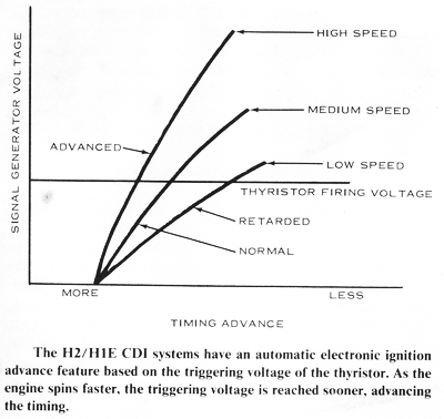
Diagramm zur Zündzeitsteuerung eines CDI-Systems
SIGNAL GENERATOR VOLTAGE HIGH SPEED MEDIUM SPEED LOW SPEED ADVANCED THYRISTOR FIRING VOLTAGE RETARDED NORMAL MORE LESS TIMING ADVANCE The H2/H1E CDI systems have an automatic electronic ignition advance feature based on the triggering
-
Thread
TosLink als einfacher Datenlink
/t10wh von Everlight. Ich hab etwas ähnliches beobachtet wenn eben kein Signal anliegt, oder der High Pegel länger als ~300µs dauert, ich denke, die AGC Schaltung in diesen Bausteinen schwingt dann, wobei es bei mir eher im Bereich von 20 Mhz war.
> Manchester ist auch nicht Gleichspannungsfrei. Wie meinst du das? Die Dauer der Phasen mit High- und Low-Level ist immer gleich, d.h. du kannst das Signal über einen Kondensator schicken, ohne dass der Pegel abhängig vom Dateninhalt weg driftet.
-
 Bild
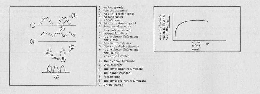
Diagramm zur Zündverstellung in drei Sprachen
1. At low speeds 2. Almost the same 3. At a little faster speed 4. At high speed 5. Trigger level 6. At a little slower speed 7. Amount of advance 1. Aux faibles vitesses 2. Presque la même 3. A une vitesse légèrement
-
Thread
Spannungsregler für Kleinverbraucher bei 1,2V gesucht
phase compensation, so that a minimum output capacitance is not required. 4.4 Input Capacitor Low-input source impedance is necessary for the LDO output to operate properly. When operating from batteries, or in applications with long lead length (> 10 inches) between the input source and the
bekommt man problemlos zwischen 100n und 10µ. Statt des vorgschlagenen LM 317 den LM117 nehmen, der ist low drop. Gibt es sogar fix und fertig für 1,2V https://www.tme.eu/de/details/ld1117dt12tr/ldo-festspannungsregler/stmicroelectronics/
-
Artikel
Fahrroboter
Motoren werden über ein digitales Signal gesteuert (orangene Ader). Das Signal besteht aus einer High-Pegel-Phase und einer Low-Pegel-Phase. Die Dauer der High-Pegel-Phase bestimmt die Zielposition (1ms = Gegen den Uhrzeigersinn bis zum Anschlag; 2ms = Im Uhrzeigersinn bis zum Anschlag). Da weder Anschlag
gesteuert werden (1000µs = Vollgas gegen den Uhrzeigersinn; 1600µs = Langsam im Uhrzeigersinn). Auf die High-Pegel-Phase folgt eine Low-Pegel-Phase von mindestens 3ms. Die eingebauten Motoren sind sehr stark und bremsen den Roboter bei einem kurzen Impuls gegen die Laufrichtung auf der Stelle ab. Dabei erhöht
-
Thread
ESP32 mit PCIe, neue LoRAWAN-Boards, Testsatz für passive Komponenten uvam
, JANPTX1N5558UG, JANPTX1N5629AUJ, JANPTX1N5665AUG, JANPTX1N5907UG and JANPTX1N5907UJ. With a high peak pulse power rating of 1.5 kW and clamping response times measured at less than 100 picoseconds in internal tests, . . . [/c] Interessant ist, dass Microchip in der offiziellen Presseankündigung
darüber, dass es eine neue, inoffizielle Version mit Unterstützung für den Raspberry Pi 5 gibt. ### HaLowLink 2 – neuer WiFi HaLow-Accesspoint Der HaLow-Standard nimmt langsam, aber sicher an Fahrt auf. Nun steht ein neuer Router ante Portas, der ein brandaktuelles Morse Micro MM8108-Modul verwendet und
-
 Bild
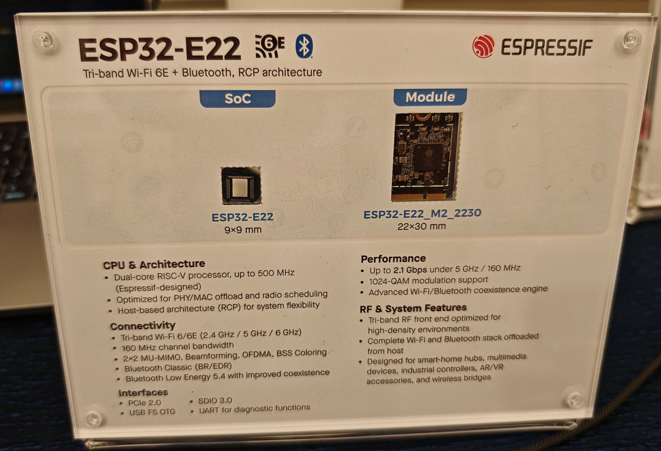
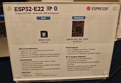
Informationsschild zum ESP32-E22 Chip und Modul
channel bandwidth 2x2 MU-MIMO, Beamforming, OFDMA, BSS Coloring Bluetooth Classic (BR/EDR) Bluetooth Low Energy 5.4 with improved coexistence Interfaces PCIe 2.0 SDIO 3.0 UART for diagnostic functions Performance Up to 2.1 Gbps under 5 GHz / 160 MHz 1024-QAM modulation support Advanced Wi-Fi/Bluetooth coexistence engine RF & System Features Tri-band RF end optimized for high-density environments Complete Wi-Fi and Bluetooth stack offloaded from host Designed for smart-home hubs, multimedia devices, industrial controllers, AR/VR accessories, and wireless bridges
-
Artikel
Relais mit Logik ansteuern
Umschalten auch mit Hilfe eines D-FlipFlops realisieren. Funktion: Im Ruhemodus liegt der Ausgang Q auf LOW, Q negiert auf High Wird auf den Takteingang von IC1A eine steigende Flanke gelegt, wird der Highpegel vom Eingang übernommen, Q ist High, der MOSFET steuert durch und läßt das Relais anziehen, Q negiert ist Low. Bei der nächsten positiven Taktflanke wird der Pegel des negierten Ausgangs wieder übernommen, jetzt Low, und der Ausgang wird wieder auf Low geschaltet. Wird ein Taster verwendet muss dieser unbedingt
-
 Bild
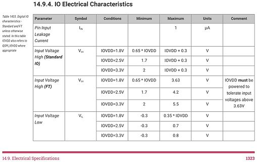
Tabelle der elektrischen Eigenschaften für IO
Input Leakage IIN unless otherwise stated. In this table IOVDD also refers to Current Input Voltage High (Standard IO) VIH IOVDD=1.8V 0.65 * IOVDD IOVDD + 0.3 V IOVDD=2.5V 1.7 IOVDD + 0.3 V IOVDD=3.3V 2 IOVDD + 0.3 V Input Voltage High (FT) VIH IOVDD=1.8V 0.65 * IOVDD 3.63 V IOVDD must be IOVDD=2.5V 1.7 4.2 V powered to IOVDD=3.3V 2 5.5 V tolerate input voltages above 3.63V Input Voltage Low VIL IOVDD=1.8V -0.3 0.35 * IOVDD V IOVDD=2.5V -0.3 0.7 V IOVDD=3.3V -0.3 0.8 V 14.9. Electrical Specifications 1323
-
 Bild
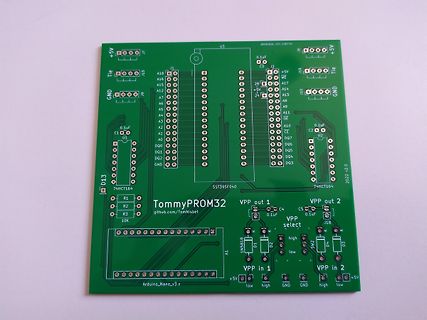
Grüne Leiterplatte TommyPROM32
2, C4, 0.1uF, C5, 0.1uF, VPP select, R1 bis R3, 10K, D1, D2, D3, 1N5819, SW2, VPP in 1, VPP in 2, low, high, GND, Arduino_Nano_v3.x, +5V
-
Artikel
8bit-CPU: bo8
GT.S K <= S ST.S S <= K GT.% K <= % ST.% % <= K RS.% S <= % SS.% % <= S SL.K B <= A , A <= 0 SL.S S LowByte <= A , S HighByte S EX.% Austausch K % ES.% Austausch S % ZO.S S <= 0 ZO.% % <= 0 ZO.V V <= 0 SE.V V <= 1 NE.V V <= not V CP.V V <= V xor U ZO.U U <= 0 SE.U U <= 1 NE.U U <= not U NE.A A wird logisch
-
Thread
ESP32-E22, schneller Chip aus dem Hause WCH, ressourcensparendes WiFi 7 uvam
STM32MP21 – preisgünstige MPU, (auch) für Computer Vision-Anwendungen In Sachen MPU gibt es bei ST low-endingen Zuwachs: die Neulinge bringen zwar verschiedene MIPI-Interfaces mit, sind in Sachen Rechenleistung aber mit nur je einem Arm Cortex®-A35 und einem Arm Cortex®-M33-Kern schwächer aufgestellt
unter https://community.st.com/t5/developer-news/scaling-stm32-microprocessors-for-cost-efficient-low-power-and/ba-p/868331 über spezielle SKUs für vierlagige Platinen berichtet: [c] STM32MP21 package options include 8mm x 8mm 225-pin and 10mm x 10mm 361-pin VFBGAs suited to 6-layer high-density interconnect
-
Thread
Leuchtstoffröhrenstarter leuchtet grün
auch bei meinem Versuch?! https://www.reddit.com/r/Radiacode/comments/1q6i26y/radiacode_110_shows_high_readings_close_to_my/ „OK so that is sort of what I would expect of low energy x-rays ...Krypton had a prominent Ka x-ray peak at 13 keV. I'm curious what other think, but I would say this is worth
bei meinem > Versuch?! > https://www.reddit.com/r/Radiacode/comments/1q6i26y/radiacode_110_shows_high_readings_close_to_my/ > „OK so that is sort of what I would expect of low energy x-rays > ...Krypton had a prominent Ka x-ray peak at 13 keV. I'm curious what > other think, but I would say this
-
Thread
Ringing "zweiter Peak" im Buck Converter
AC-Kopplung messen? Guter Hinweis. AC-Kopplung nehme ich persönlich um den Zeitpunkt für digitale (Low und High-Wechsel) Signale zu ermitteln und daher auch für Trigger-Eingang. Bei der Bewertung von analogen Signalen und deren Amplititude eher nicht, weil ich nicht die Veränderung der Kurvenform
-
Thread
STM32I0 zum laufen (flashen) bringen (VSCode und PlatformIO)
mode : Software reset 21:39:52 : Device ID : 0x417 21:39:52 : Revision ID : Rev X 21:39:52 : Debug in Low Power mode is not supported for this device. 21:39:52 : UPLOADING OPTION BYTES DATA ... 21:39:52 : Bank : 0x00 21:39:52 : Address : 0x4002201c 21:39:52 : Size : 104 Bytes 21:39:52 : Bank : 0x01 21:39
haben einen Debug-UART integriert, und sie sind deutlich schneller, weil stärkerer Prozessor und High-Speed USB statt Full-Speed USB. https://www.reichelt.de/de/de/shop/produkt/in-circuit-debugger_-programmierer_fuer_stm32_usb-c-330303 fchk
-
Thread
Türklinger verstärken ohne elektrischen Eingriff in Hausanlage
Staubsaugen oder Brüllen) testen, ob es dann zu Fehlauslösungen kommt. Wenn das läuft Optimierung auf low Power.
Oszi kann keine Frequenz mehr messen, aber der Chip regiert nach wie vor sauber, indem der Ausgang low geht, und sauber low bleibt, egal ob man mir der Hand drüber geht. Also genau das, was ich will. Leider will ich das mit weniger als 5V :-(. Aber man lernt ja dabei. So nun geht es in den Datenblättern
-
Thread
Neue Bauteile: MCX W72, RF-Absicherungsbauteile und intelligentes Hühnerfutter
Leveraging Murata’s proprietary ceramic and electrode materials, thin-layer molding technology, and high-precision stacking technology, the new 1.25kV MLCC addresses these needs, supporting the latest SiC MOSFET technologies. The inherent advantages of C0G in accordance with EIA standards - low loss and
NLX is designed to withstand RF pulsed power levels up to 500 W, delivering exceptional durability, high isolation, low loss, and wideband operation. Its high-standoff capability enables the device to block extremely high RF power or voltage, protecting sensitive receivers, minimizing energy leakage, and
-
 Bild
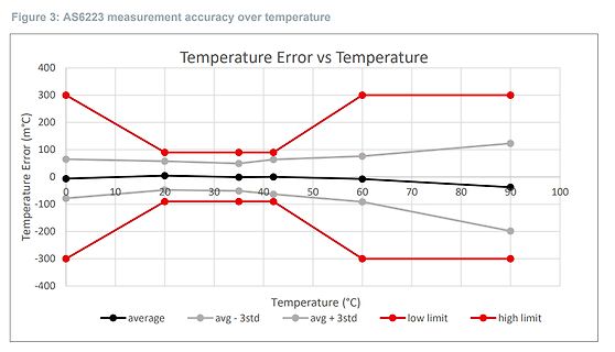
Diagramm der Temperaturfehler des AS6223 über der Temperatur
-100 -200 -300 -400 Temperature (°C) 10 20 30 40 50 60 70 80 90 100 average avg - 3std avg + 3std low limit high limit
-
 Bild
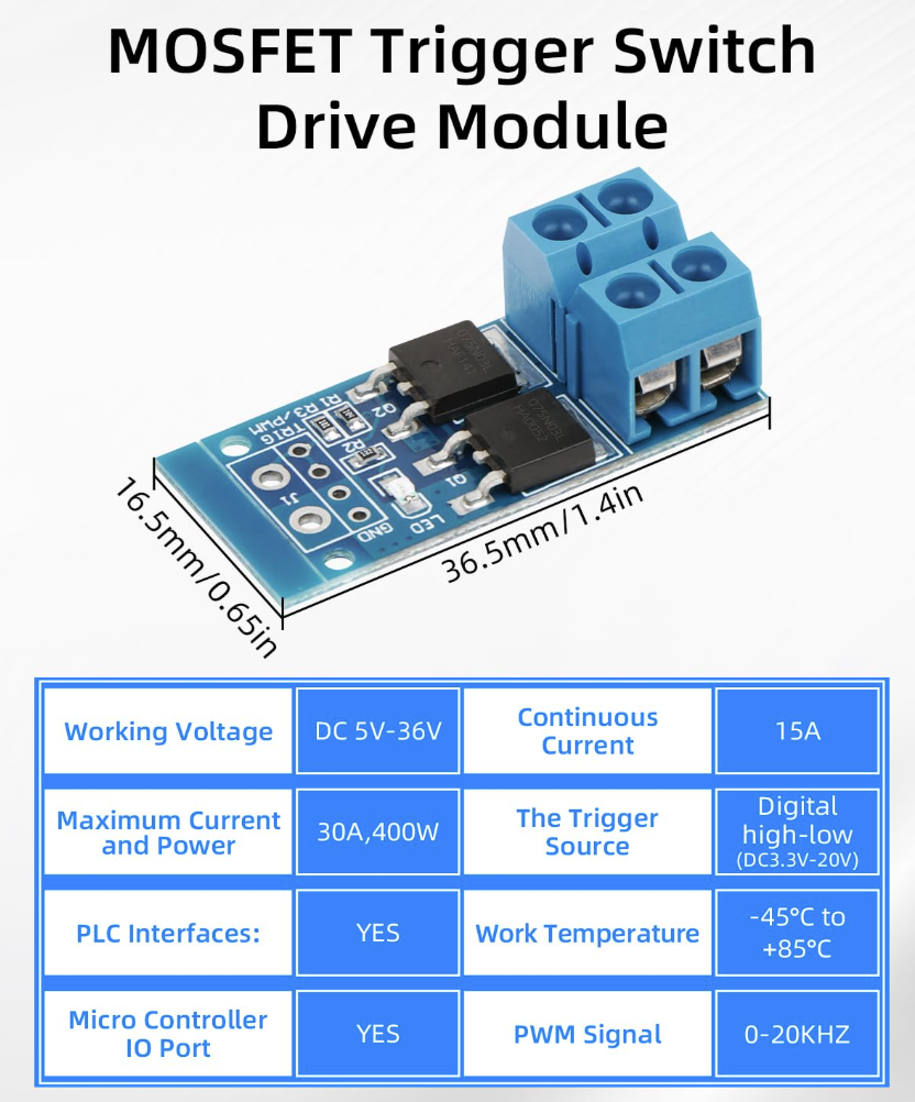
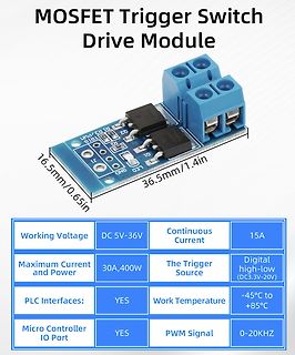
MOSFET Trigger Switch Drive Module mit technischen Daten
Voltage DC 5V-36V Continuous Current 15A Maximum Current and Power 30A,400W The Trigger Source Digital high-low (DC3.3V-20V) PLC Interfaces: YES Work Temperature -45°C to +85°C Micro Controller IO Port YES PWM Signal 0-20KHZ
-
Thread
[V] SMD-Bauteile auf Tape & Reel (Restmengen / Rollenreste)
8 pF 50 VDC 0.1 pF 0402 C0G (NP0) 12000 Diodes Inc DMC2400UV MOSFETs 20V N P Ch 20VDSS 0.45W Low RDSon 1400 Littlefuse 1812L150/12DR Resettable Fuses - PPTC 12V 1812 1.50A POLYFUSE 700 Rohm 2SC4102U3T106R Bipolar Transistors - BJT Transistor for high-volt amp 1600 FTDI FT230XS
Advanced Load Management Prod 1000 Ricoh R3111Q331C-TR-FE Supervisory Circuits Low Voltage Detector 490 Microchip MCP120T-450I/TT Supervisory Circuits Open Drain Low 2100 Analog Devices C2955ITS8-2TMPF Supervisory Circuits Pushbutton On/Off Cntr w/ Auto Turn-On 120 Yageo
-
Thread
Pullup-Widerstand Stromverbrauch zu hoch
an einen Portpin statt an Vcc zu hängen? uC alle x ms aufwecken, Pulluppin auf High, messen, Pulluppin auf Low u.s.w. Da geht der Stromverbrauch auch runter. Gruß Gunther
ist. Ich verwende den digitalen Eingang als Interrupt. (RISING to trigger when the pin goes from low to high). Damit der Atmega den RISING Impuls korrekt erkennen kann, wird der Eingang durch den Pullup im Schaltmoment auf HIGH gezogen. Meine Annahme war, dass der Interrupt ohne den Pullup bzw. mit
-
Thread
Tankanzeige eines E36 mit Mikrocontroller Steuern
Blödsinn, kostet auch nicht mehr als ein Reedrelais. Hast du da eine günstige Quelle für solche Low-Power-Out Optomos? mfg mf
Manche Anzeigen werden bei BMW auch vom Bus generiert. Es Low und high Kombis. Prüfe zuerst wie das beim E36 ist.
-
Thread
MOSFET, NCh IRLML6244 Alternative (größere Bauform)
Schalten von Vcc parasitär versorgen: nämlich dann, wenn du Vcc abschaltest und ein Dateneingang mit "high" angesteuert wird. Das Abschalten mit dem HighSide-P-Mosfet geht also so: 1. Datenleitungen auf "low" legen 2. Vcc über den Mosfet abschalten
Hallo R42, Danke für euren Input. Rainer W. schrieb im Beitrag #7987532: > Wo sollte da bei High am Ausgang mehr Strom fließen? Scheinbar nirgendwo. Ich war da fälschlicherweise der Annahme, dass das High Signal mehr verbraucht als das Low Signal. Des Weiteren dachte ich, dass das High Signal
-
Thread
PIC Mikrocontroller noch aktuell ?
Was halten wir denn vom PML100B? Das scheint die Low-Power MCU zu sein, die in den ganzen Akkubetriebenen Lampen steckt. https://www.lcsc.com/product-detail/C49173943.html Außerhalb der low-power Diskussion macht ein PIC eigentlich keinen Sinn.
– Integrated programmable gain stage, up to 32x • One general-purpose amplifier (GPAMP) • Three high-speed comparators (COMP) with 8 bit reference DACs – 32ns propagation delay in high-speed mode – Support low-power mode operation down to 1µA • Programmable analog connections between ADC, OPAs