-
Thread
Virtual RS232 am USB send DTR aber wie ?
. Vermutlich ist im USB-Kit der DTR-Pin des intern verbauten USB-UART-Wandlerchips mit einen High-Side-Switch verbunden und die 5V Betriebsspannung kommen nur wenn DTR gesetzt ist.
-
 Bild
Bild
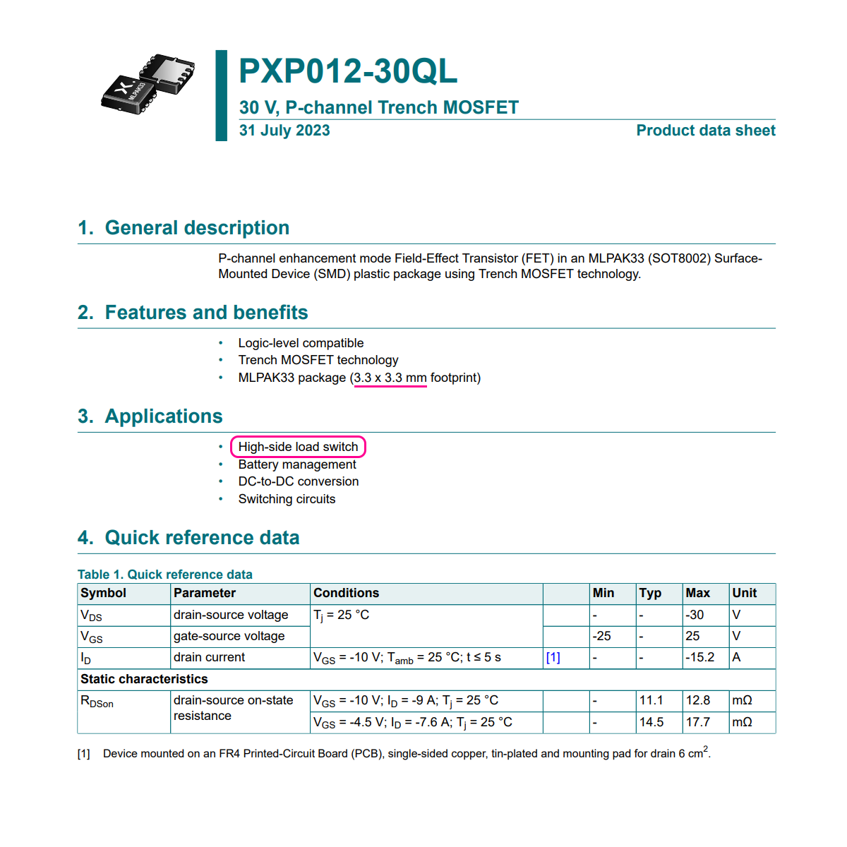
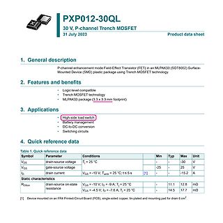
Datenblatt PXP012-30QL Trench MOSFET
compatible Trench MOSFET technology MLPAK33 package (3.3 x 3.3 mm footprint) 3. Applications High-side load switch Battery management DC-to-DC conversion Switching circuits 4. Quick reference data Symbol Parameter Conditions Min Typ Max Unit VDSS drain-source voltage TJ = 25 °C - -30 V VGS gate-source
-
 Bild
Bild
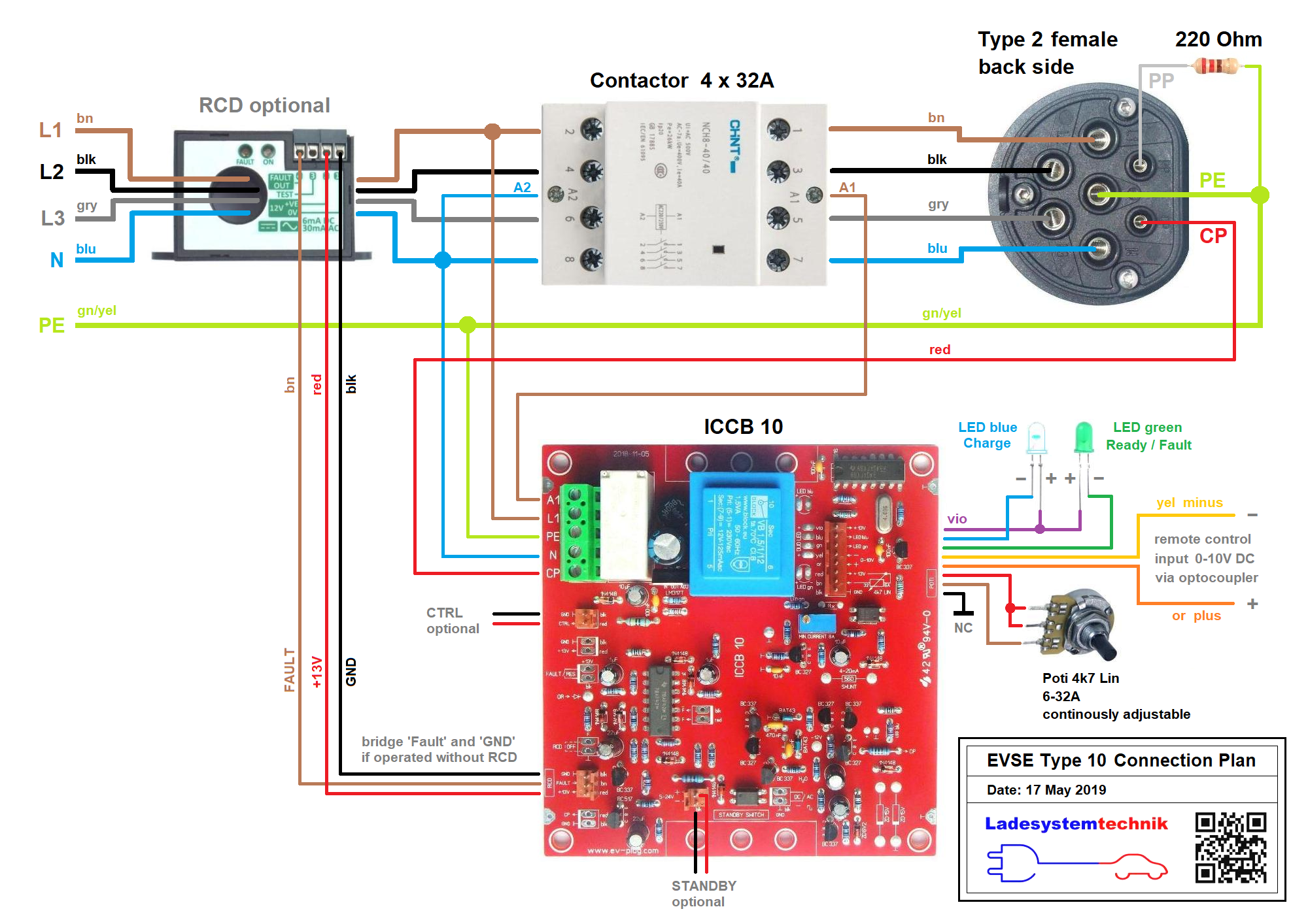
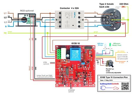
Verdrahtungsplan EVSE Type 10 Anschluss
RCD optional L2 blk L3 gry N blu PE gn/yel bn red blk Contactor 4 x 32A A1 A2 Type 2 female back side PP 220 Ohm blk gry blu gn/yel CP ICCB 10 LED blue Charge LED green Ready / Fault vio remote control input 0-10V DC via optocoupler + or plus CTRL optional Poti 4k7 Lin 6-32A continuously adjustable
-
 Bild
Bild
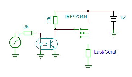
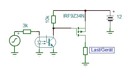
Schaltplan mit Optokoppler und MOSFET-Treiber
3k 10k IRF9Z34N 12 Last/Gerät
-
Thread
12V 2A per Raspberry Pi (3,3V) schalten
https://www.google.de/search?q=high+side+load+switch&udm=2
Vergleich zum Transistor. Wenn ihr euch einig seid, dass ich etwas übertreibe mit meinem High Side, dann sollte ich mich wohl auch grundsätzlich auf Low Side einlassen. Wenn ich das richtig rausgelesen habe, gäbe es bei Variante 2 (low-side) allerdings noch die Herausforderung, einen passenden
-
Thread
mehrkanaliger Smartschalter 24V
allerdings nur 1A pro Kanal: https://www.infineon.com/cms/de/product/power/smart-power-switches/high-side-switches/profet-plus-24v-automotive-smart-high-side-switch/btt6200-4esa/ Oder wenn es etwas mehr Strom (4A/7A) sein soll: https://www.infineon.com/cms/de/product/power/smart-power-switches/multichannel-spi-switches-controller/spoc-plus-2-multichannel-spi-high-side-power-controller/bts72220-4esa/?intc=reco Der hat noch eine optionale SPI wenn du bei deinen vielen Lampen noch ein paar Pins sparen willst.
-
Thread
[VS] LEDs weiß (WW/CW/NW) / rot / gelb
verlötet (ergo muss man "iwie" gleich das ganze Kapton flexboard verwerten). "Meine" side-leds waren deutlich..."grobschlächtiger" und daher gut mit dem Kolben lötbar. Klaus.
ich zum Schluß gekommen, daß man diese Leds dank der Pinform auch seitlich montieren kann. Unter Side-Leds verstehe ich aber SMD-Leds mit Lichtausgang an der Seite, so wie im Anhang...
-
Thread
LTspice: OpAmp Eingänge vertauscht in Konstantstromquelle
Werden In+ und In- vertauscht angeschlossen, funktioniert es (wie erwartet) nicht. 2) Eine High-Side Konstantstromquelle mit einem p-Kanal-MOSFET und einem Messwiderstand: Diese Schaltung funktioniert nur, wenn ich den Messwiderstandknoten an das im Symbol als In+ bezeichnete Pin anschließe und den
-
Thread
Mikrocontroller mit 5V
ausgibt? Könnte man so einen Output mit dem Gate eines p-Channel-MOSFET verbinden, welcher als High-Side-Switch auf 5V fungiert? Wenn man "High" ausgibt zieht ein Pullup das Gate auf 5V wodurch der MOSFET abschaltet, gibt man "Low" aus ist es an?
> Könnte man so einen Output mit dem Gate eines p-Channel-MOSFET > verbinden, welcher als High-Side-Switch auf 5V fungiert? Ja. Und man kann damit auch LL-MOSFET ansteuern, für die 3,3V zu wenig wäre. Allerdings nur mit niedrigen Frequenzen.
-
Thread
IP-SAT TV Bandbreitenreduktion
und lässt sich scheinbar auch auf openatv installieren: https://www.opena.tv/viewtopic.php?p=459732&sid=4b5b9d7c1ac8c66487f9b8ca63d6f308#p459732
-
 Bild
Bild
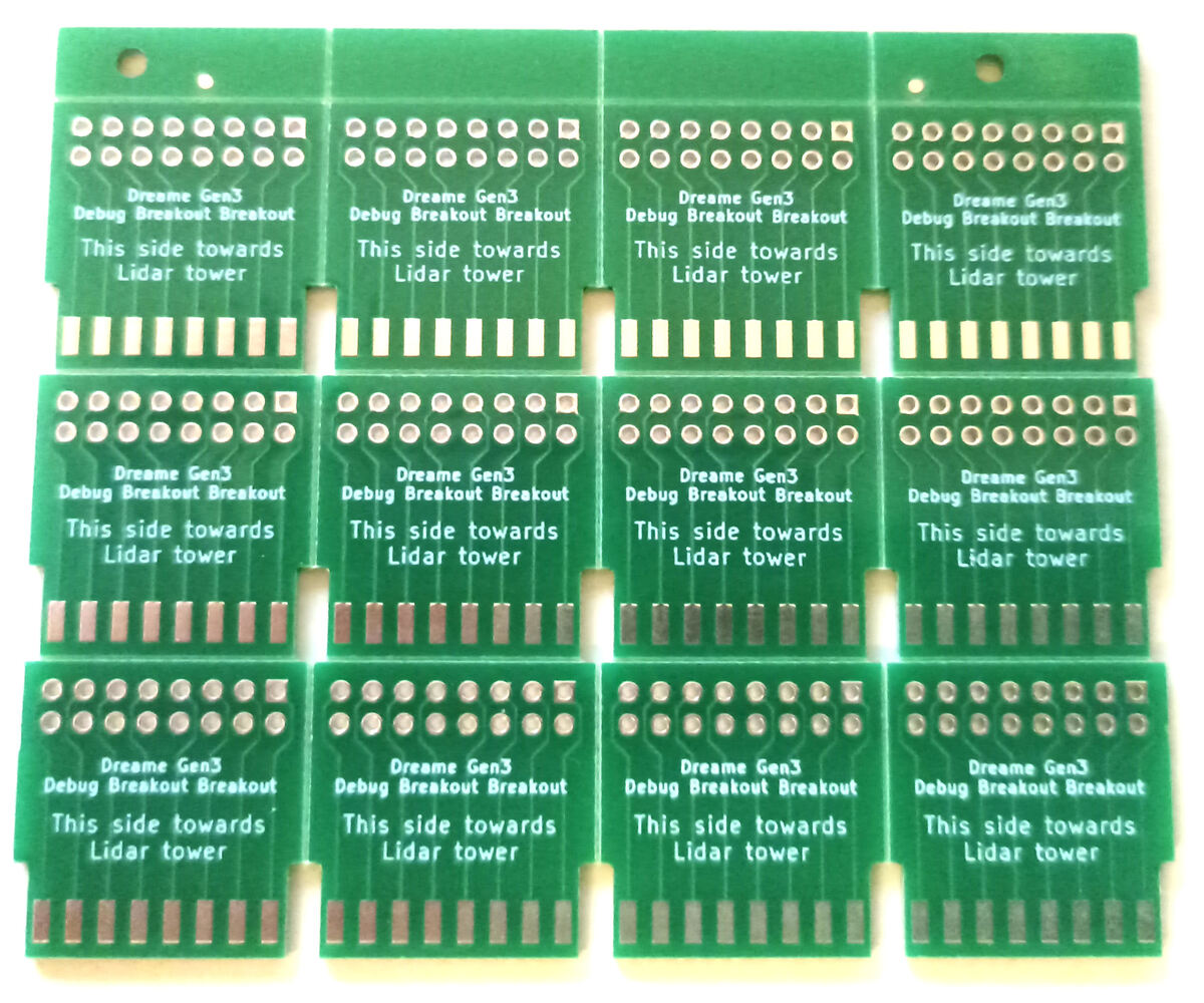
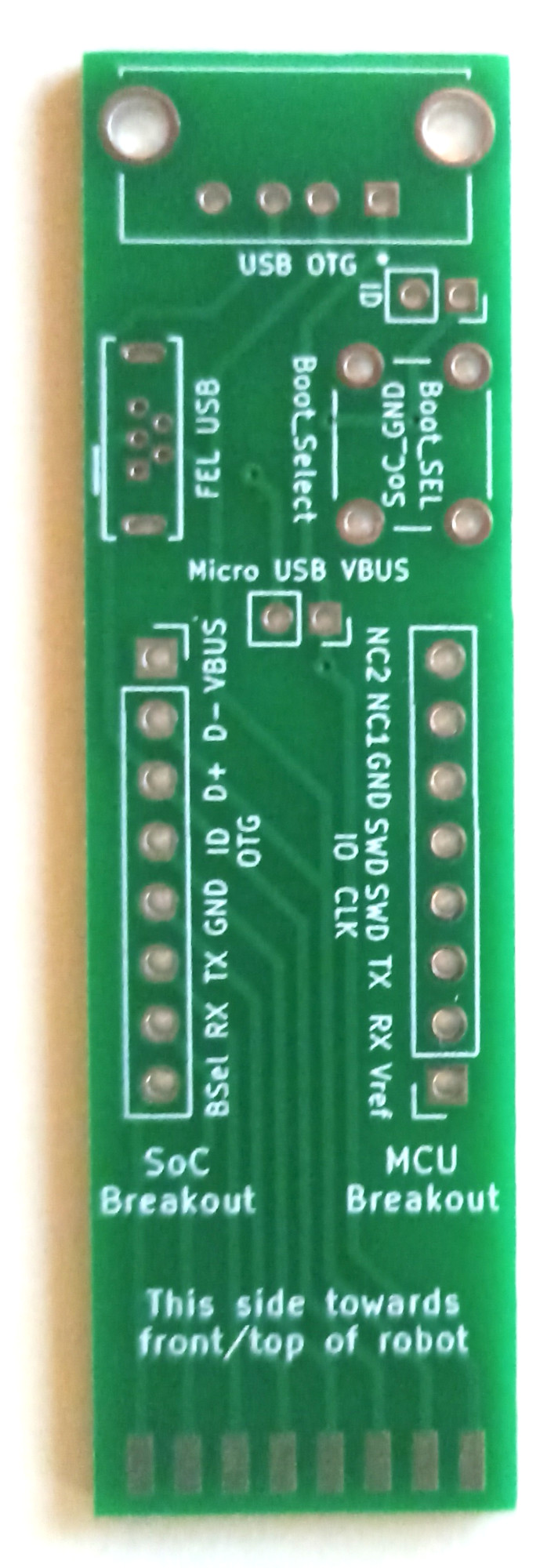
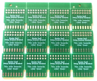
Mehrere Dreame Gen3 Debug Breakout Leiterplatten
Dreame Gen3 Debug Breakout Breakout This side towards Lidar tower
-
 Bild
Bild
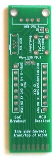
Grüne Leiterplatte SoC und MCU Breakout Board
VBUS NC2 NC1 GND SWD SWD TX RX CLK 10 RX TX GND ID OTG D+ D- BSel SoC Breakout MCU Breakout This side towards front/top of robot
-
 Bild
Bild
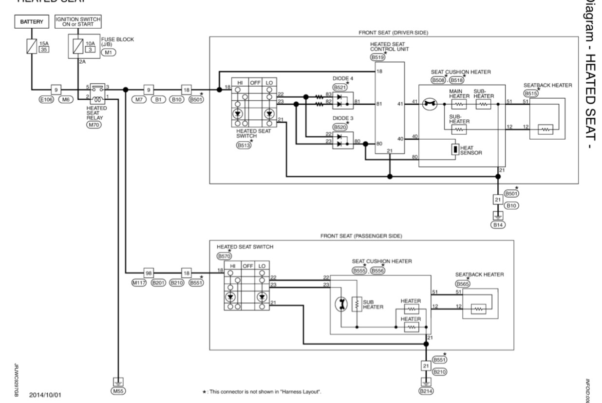
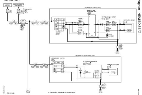
Schaltplan einer Sitzheizung
FUSE BLOCK M1 M7 B1 B501 HEATED SEAT RELAY M70 5 9 18 20 21 22 23 80 81 40 41 FRONT SEAT (DRIVER SIDE) HEATED SEAT CONTROL UNIT B519 DIODE 4 18 HI OFF LO B520 DIODE 3 21 22 23 SEAT CUSHION HEATER B508 B516 MAIN HEATER SUB HEATER 81 51 41 40 12 21 SEATBACK HEATER B515 SUB HEATER 51 12 B501 B10 B14 HEAT SENSOR B551 B210 B214 FRONT SEAT (PASSENGER SIDE) HEATED SEAT SWITCH B570 HI OFF LO 18 22 23 21 SEAT CUSHION HEATER B555 B556 SUB HEATER 22 23 21 SEATBACK HEATER B565 51 12 B201 B210 B551 M117 M55
-
Thread
PWM- Lüftersteuerung mit esp32 WROOM
die Drehzahl auswerten. Das geht schwierig, wenn du den Bezugspunkt für das Signal ständig per Low-Side PWM änderst. Deswegen hab ich für das Ein/Aus-schalten des Lüfters einen High-Side-Switch vorgeschlagen.
würdest du die 12V-Versorgung des Lüfters per PWM schalten, und mit einem Logic-Level-FET wohl LOW-Side. Hättest du auch früher aufklären können, dann hätten wir uns die ganze Diskussion sparen können.
-
Thread
[V] Transistoren, ICs analog/digital, Opto,.
INA290A3QDCKRQ1, TI: Precise Current Sense Amplifier -> 0,75€/Stk. 305x UCC27322QDGNRQ1, TI: 9A Low-Side MOSFET Driver -> 0,50€/Stk. 46x SI8235AB-D-IS, SiLabs: Galvanisch isol. Gate Treiber -> 2,00€/Stk. 6x HDC2080DMBR, TI: Feuchtigkeitssensor -> 0,75€/Stk. 10x AP21510FM
, 0603 Preis pro 100 Stk. -> 2,00€ 1900x LSA67k, Osram: Side LED rot Preis pro 100 Stk. -> 2,00€ 1x LB070WV8, LG: TFT 800x480 LVDS -> 10,00€ Transistoren, Dioden: 9000x SI2315BDS-T1-E3,
-
Thread
Firmware Code Injection Angriffe
Robustheit von "Detection and Recovery" -Mechanismen zu testen. Ich finde viel Info zu Fault-Injection und Side-Channel Attacks aber wenig zu code injection und wollte fragen ob ihr dazu gute Ressourcen (z.B. Bücher, Paper oder einfach gute Suchbegriffe) damit ich da mein Wissen vertiefen kann. Vielen Dank!
Achja: Andrew meinte: > Ich finde viel Info > zu Fault-Injection und Side-Channel Attacks aber wenig zu code injection > und wollte fragen ob ihr dazu gute Ressourcen (z.B. Bücher, Paper oder > einfach gute Suchbegriffe) damit ich da mein Wissen vertiefen kann. > Vielen
-
Thread
Raspberry Pi Pico 2-Alternativen, mehr PIOlib und Abschied vom RK3588
wie gar nicht auskennt, sei lediglich das folgende Zitat wiedergegeben: [c] “I don’t think either side had a clear victory or would have had a clear victory if this case is tried again,” US District Court Judge Maryellen Noreika said, according to Reuters. [/c] ### Blues Cygnet - kostenreduzierter
-
Thread
PCF8574 Optokoppler Input/Output
Arno Für den Ausgang möchte ich bei diesem Push-Pull bleiben, probiere dann später mal die High-side Switches aus. Bei einem nicht initialisierten Port auf GND zu gehen, passt so für meine Anwendung. Ich sehe schon, dass für euch die Rechtschreibung sehr wichtig ist. Möchte mich hier aber auf
> Für den Ausgang möchte ich bei diesem Push-Pull bleiben, probiere dann > später mal die High-side Switches aus. Nichts geht leichter. Bis 45 mA zu Erde kann diese Schaltung schaffen.
-
Thread
Tuya WiFi dimmer. Kennt jemand das teil?
mediarath.de/products/esp-02s-tywe2s-esp8285-esp8266-wifi-modul-arduino-ide-serial-board-tasmota?_pos=2&_sid=05333f095&_ss=r
-
Thread
Strommessung bei High-Speed Motor
musst du kompensieren sonst schiebst du nur Blindstrom in die Maschine. 6. Die Stromsignale bei Low Side sehen immer böse aus. Lass den ADC mit DMA jeden pwm Zyklus samplen. Dann kannst du die Mitteln. Oder auch hier einzelne Stromvektoren bilden und mit Phase lag des Filters als auch der Änderung der
halbe PWM Frequenz Regelung und doppelte PWM Frequenz Sampling bei (Phasen-Strommessung, 2 bei Low side). Was soll das werden wenn es fertig ist? Oder Spaß am Spiel? Gruß Alex
-
Thread
Wie viele Schrittmotoren kann ich über einen ESP32 ansteuern?
www.az-delivery.de/products/esp-32-dev-kit-c-v4 https://www.az-delivery.de/products/esp32-s2-mini?_pos=1&_sid=caf31e2e1&_ss=r
-
Thread
Problem bei der Ansteuerung eines Transistor als Schalter mit PWM Signal
Transistoren verwendet man meistens in der Emitter-schaltung. Michael B emppfiehlt hier meistens einen High-Side-Switch für den Automotive-Bereich ((das wäre also ein PNP-Mosfet)), ist wohl so üblich. https://www.elektormagazine.com/articles/high-side-low-side-switching Über die grünen Doppelpfeile navigieren
-
Thread
Mikrocontroller Einstieg
Portable Speichermodelle, Energieverbrauch der Software, massiv parallele Architekturen wie GPUs, Side-Channel-Attacks, Optimierung der Software um diese Dinge so effizient wie möglich auszunutzen) nutzen trotzdem auch ganz entspannt High-Level-Frameworks wie Arduino und Hochsprachen. Weil das für viele
taught me that you just sort of look at each instruction, you write your instructions on the right side of the page, you write the addresses over on the left side, and you then look up the hex data for each instruction – you could assemble it yourself. Wer sich keinen Assembler leisten konnte, konnte
-
 Bild
Bild
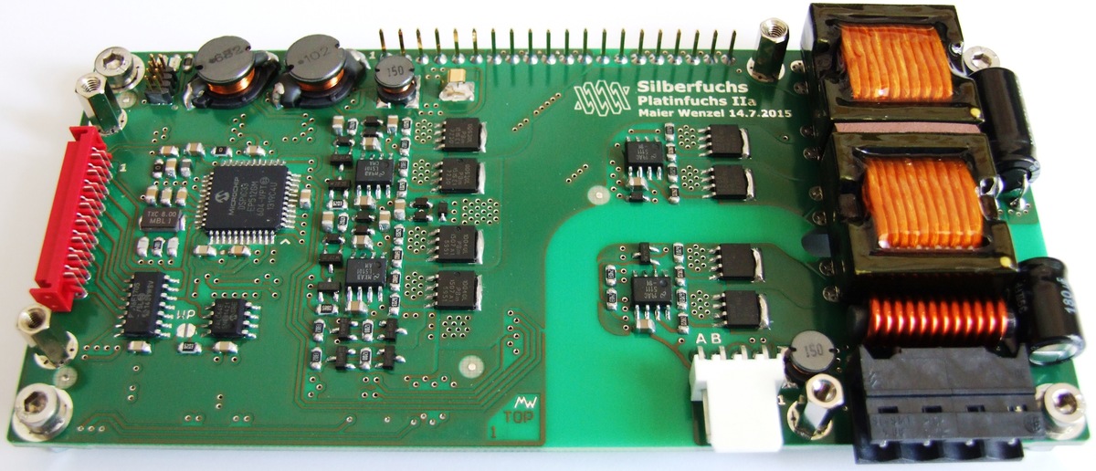
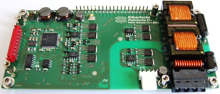
Leiterplatte Silberfuchs Platinfuchs IIa
Silberfuchs Platinfuchs IIa Maier Wenzel 14.7.2015 682 102 150 150 TOP 1
-
 Bild
Bild
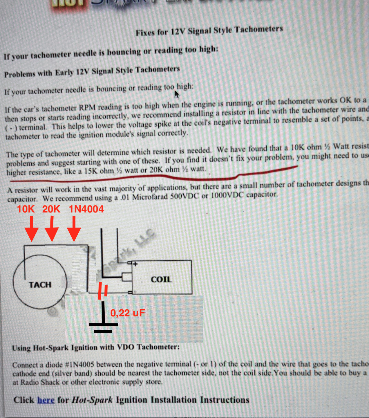
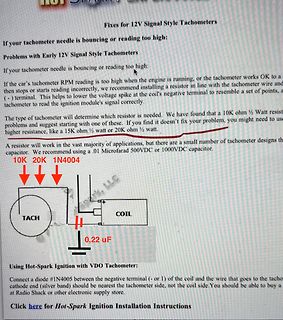
Abfotografierter Text und Schaltskizze für Tachometer-Reparatur
coil and the wire that goes to the tacho cathode end (silver band) should be nearest the tachometer side, not the coil side.
-
Thread
Fallende Flanke diskret erkennen
messen. Meine Hardware (siehe Anhang) besitzt aber neben dem ESP32 auch einen TPS281C100A High-Side Switch mit Strombegrenzung. Dieser High-Side Switch dreht bei jedem Kurzschluss verlässlich den Ausgang ab. Nun hätte das Ding theoretisch auch einen Open-Drain Fault Ausgang... nur leider triggert
-
Thread
Sonderzeichen
but different cases are also not allowed by default, but can be enabled on installation with the side-effect of making the underlying partition's filesystem case-sensitive,[6][7] even for the Win32 subsystem. Network authentication for UNIX systems relies on the insecure NIS protocol (LDAP- and Kerberos-based
-
Thread
Tastatur-Problem bei Linux Mint
entsprechenden Tasten - ist absolut tot... Hier: https://forums.linuxmint.com/viewtopic.php?t=425391&sid=1fe55960deb5bbd000986856a05e5111 steht unter anderem: I've tried some old version of mint: 20.3 : ok 21 : ok 21.2 : keyboard doesn't work!! 21.3 : multiple strokes 22 : multiple strokes
-
Artikel
Leistungselektronik
verwendeten Schaltungstopologien in der Leistungselektronik dargestellt, und kurz besprochen: Low-Side–Schalter: Der Halbleiter schaltet eine Last gegen GND – auch als LS-Schalter bezeichnet. Die Last ist fest mit der Versorgungsspannung verbunden. Der Treiber kann hier zwar direkt an GND geschaltet
an möglichst direkte Anbindung an den Bezugspunkt (direkt an Source bzw. Emitter) zu achten. High-Side–Schalter: Der Halbleiter schaltet eine Last an die Versorgungsspannung – auch als HS-Schalter bezeichnet. Die Last ist fest mit GND verbunden. Hier wird der Treiber nicht mit GND verbunden, jedoch trotzdem