SAIC Microelectronics-Ingenieur - Frequenzabweichung: Über Umgebungstemperatur (4,0V~5,5V) und (-20 ~ 85℃) nicht mehr als ±1%. - Integrierter Quarzoszillator, externer 32k-Oszillator anschließbar als Base Timer-Taktquelle, kann STOP aufwecken. Integrierter Niederfrequenz-128kHz-LRC-Oszillator -
Stromsparmodi: - IDLE-Modus, kann von jedem Interrupt aufgeweckt werden - STOP-Modus, kann von INT0~2 und BaseTimer aufgeweckt werden
http://www.szallvision.com Allvision technology Inc. Ver:A Contents Rev s on H s ot ry Con en ts 1 Bas c Spec ca oni ti s 1.1 Display Specifications 1.2 Mechanical Specifications 1.3 Active Area / Memory Mapping & Pixel Construction 1.4 Mechanical Drawing 1.5 Pin Definition 2 Abso u e Max mum Ra ng ti
and allows centering of the video information within the rastered area. Horizontal Deflection The base of the deflection driver (Q203) is driven by the base drive transformer. Driver and Coil This transistor operates as a saturated switch, providing the current for the Circuit A20 deflection coil. The
die Sättigung durchsteuerst, viermal drei Schotkkydioden vom Kollektor zu den jeweils drei anderen Basen, um eine ungewollte Mehrfachansteuerung zu blockieren.
wiedersprechen !? > viermal drei Schotkkydioden vom Kollektor zu den jeweils drei anderen > Basen Viermal drei macht nochmal 12 zusätzliche Bauelemente... Sicher nicht mehr auf meinem Lochraster-Aufbau, evt. aber auf einer noch zu gestaltenden Platine. Die Grundidee ist sicher nicht schlecht
Unterschied. Nur in der Auswertung. DA aber niemand auf die Idee gekommen wäre seinen je nach Optionen 20-30 kg schweren HP8753C im Wert einer Eigentumswohnung durch die Gegend zu schleppen um verlegte Kabel zu überprüfen ist das bei den klassischen Messgeräten halt jeweils Aufgabe von speziellen Geräten
Base64 U. schrieb im Beitrag #7652763: > Die SSA3021X-Plus -> SVA1032X konvertierung scheint wirklich sehr > attraktiv zu sein. \ > Der SSA3021X-Plus kostet bei Batronix ~130€ brutto mehr als der > SVA1015X
Absolute Maximum Rating System (IEC 134). SYMBOL PARAMETER CONDITIONS MIN. MAX. UNIT VCBO collector-base voltage open emitter BD135 − 45 V BD137 − 60 V BD139 − 100 V V collector-emitter voltage open base CEO BD135 − 45 V BD137 − 60 V BD139 − 80 V VEBO emitter-base voltage open collector − 5 V I collector
Links tenist.JetztkannmandasBandmitdemDrehkondensator 1hps://b-kainka.de/; hps://www.b-kainka.de/basel0.hm 2 langsam abscannen; an einigen Sellen hör man «Blips», 3hps://www.elekronik-labor.de/HF/KWaudion20.hml d . .F-Träger, oder verzerrte Sprache Dies kann ein AM- Da keine Publikaon dieses
die Drawdio-Schaltung gilt: https://electronics.stackexchange.com/questions/134058/do-i-need-a-base-resistor-for-a-bjt MfG, Achim
Lautsprecher, und der kann dann direkt (über einen 100uF Elko) an den TLC551 Ausgang, denn der kann die 20mA, die man der Batterie zumuten kann, leicht selber.
das nirgendwo. FOS ist die Fachoberschule, die mit dem > Abschluß besucht werden kann. Bärbel Bas hat die Fachoberschulreife, wiki Bärbel Bas ---> https://de.wikipedia.org/wiki/B%C3%A4rbel_Bas#Leben_und_Beruf Fachoberschulreife: https://de.wikipedia.org/w/index.php?title=Fachoberschulreife&redirect
nirgendwo. FOS ist die Fachoberschule, die mit dem >> Abschluß besucht werden kann. > > Bärbel Bas hat die Fachoberschulreife, wiki Bärbel Bas ---> > https://de.wikipedia.org/wiki/B%C3%A4rbel_Bas#Leben_und_Beruf > Fachoberschulreife: > https://de.wikipedia.org/w/index.php?title=Fachoberschulreife
C20.asc February 19, 2024 date Mon Feb 12 04:13:22.427 pm 2024 # ABSCHALTEN base hex timestamps absolute internal events logged // version 8.5.0 Begin Triggerblock Mon Feb 12 04:13:22.427 pm 2024 byte 1
Unit VDS drain-source voltage 25 °C ≤ T j 175 °C - 100 V V drain-gate voltage 25 °C ≤ T ≤ 175 °C; R = 20 kΩ - 100 V DGR j GS VGS gate-source voltage -20 20 V Ptot total power dissipation Tmb = 25 °C; Fig. 1 - 405 W D drain current V GS= 10 V; Tmb = 25 °C; Fig. 2 [1] - 120 A V = 10 V; T = 100 °C; Fig. 2
aktuelle BMP-Hardware passt z.B. da rein: https://www.reichelt.de/kunststoffgehaeuse-67-x-32-x-20-mm-5-stueck-rx2kl07-s-5-p292746.html?&nbc=1
war der ordentlich schnell. Für meine modifizierte Variante mit F407 und Ethernet habe ich so an die 20 MB/s in Erinnerung. Da muss irgendwas faul sein.
handgewickeltem 0.1mm-Draht oder dünner? https://de.wikipedia.org/wiki/Spulenwickeltechnik#:~:text=Wilde%20Wicklung,-Bei%20dieser%20Art&text=Wilde%20Wicklungen%20werden%20in%20der,Steigung%20gegen%C3%BCber%20dem%20Drahtdurchmesser%20verlegt. Das Foto zeigt eine aufgesägte ZS1052 - Wilde Wicklung. Und das
Schaltfrequenz? Muss ich später erst ermitteln. Jedenfalls im nicht hörbaren Bereich. Somit >20kHz.
Moin, der 8552 hat einen "Null-Linien" Ausblender-Knopf. Der ist als "Base Line Clipper" markiert. Mit diesem Regler kann man den unteren Bereich total verschwinden lassen. Nicht vergessen, den mal vom Anschlag zu Anschlag drehen, um zu sehen ob dies die Ursache ist. http://www.azurelectronics.com/Operating%20HP%20141T%20Spectrum%20Analyser.htm#4-1 Übrigens, schliess mal einen Oszi an den Video Ausgang und Sweep. Da kann man die Anzeige am Oszi duplizieren und geht nicht durch die Ablenkverstärker. Die
Miscellaneous Registers - FT81x Series Programmers Guide Section 3.6 - Document inspecific about base address // Addresses assumed to be defined as offsets from the base address called RAM_REG and located at 0x302000 #define REG_CPURESET 0x20 #define REG_PWM_HZ 0xD0 #define REG_INT_MASK 0xB0 #define
immer da ankommt). Der ACS712 hat 2.5V ohne zu messenden Strom und 66mA beim 30A-Type, 100mA beim 20A-Type und 184mA beim 5A-Type. Beim 30A-Type machen 2A 27 Schritte aus, was sicher genau genug zu messen ist, wenn man zwischen 20A und 30A messen will. Der 20A-Type, mit seinen 100mA lässt sich nicht
Frank O. schrieb im Beitrag #7652164: > 20 oder 20 mH Sollte natürlich 20 oder 30mH heißen.
................20 9.1.13 Index 1018 IdentityObject...................................................................................20 9.1.14 Index 1800: TransmitPDOParameters.........................................
is for Cypress For our analysis, we created logs under various conditions. For chips, their code base is similar to Broadcom chips [23], and we can example, we looked into shutdown logs with Find My enabled and use it as a base for reverse-engineering and function naming. disabled, with and without
Miscellaneous Registers - FT81x Series Programmers Guide Section 3.6 - Document inspecific about base address // Addresses assumed to be defined as offsets from the base address called RAM_REG and located at 0x302000 #define REG_CPURESET 0x20 #define REG_PWM_HZ 0xD0 #define REG_INT_MASK 0xB0 #define
Reference No.: BRClearance No.: BRT#129 To load a JPEG image at address 0 then draw the bitmap at (10, 20) and (100, 20): cmd_loadimage(0, 0); ... // JPEG file data follows cmd(BEGIN(BITMAPS)); cmd(VERTEX2II(10, 20, 0, 0)); // draw bitmap at (10,20) cmd(VERTEX2II(100, 20, 0, 0)); // draw bitmap at (100,20
with the RoHS directive. The RoHS compliant selection is Soldering temperature/time, IEC 60068-2-20 indicated together with the information on the RoHS compliance. Some See > 'Resistance to soldering heat'. products of that product group however do contain materials (e.g. Cd) Solid insulation listed
^ | GND --------------o------------- GND Dioden: 2x BAS81 oder 1x BAV99 [/pre] Purzel H. schrieb im Beitrag #7596291: > Ein 22mOhm shunt passt fuer 4A, machen 88mV. Fuer 3.3V benoetigt man > dann eine Verstaerkung von etwa 41. Und bei 100µA sind
Die Offset Drift und die Drift der passiv Elemente sind eher ein Thema. Wenn das ganze nur um 20...30 Grad Temperatur so genau sein muss, geht das. 24 bit adc gibt es günstige bei TI.com, da geht es wohl hin.
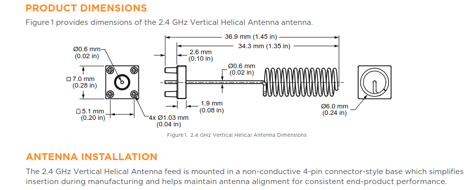
34.3 mm (1.35 in)
Ø0.6 mm (0.02 in)
7.0 mm (0.28 in)
2.6 mm (0.10 in)
Ø0.6 mm (0.02 in)
5.1 mm (0.20 in)
1.9 mm (0.08 in)
Ø6.0 mm (0.24 in)
4x Ø1.03 mm (0.04 in)
Figure 1. 2.4 GHz Vertical Helical Antenna Dimensions
ANTENNA INSTALLATION
The 2.4 GHz Vertical Helical Antenna feed is mounted in a non-conductive 4-pin connector-style base which simplifies insertion during manufacturing and helps maintain antenna alignment for consistent end-product performance.
Board¹ passt von der Ausstattung her wirklich perfekt, aber es ist so dermaßen² EOL... "After about 20 years of WRAP, ALIX and APU, it is time for me to move on to different things." Es ist klar, dass es keinen gleichwertigen Ersatz geben kann, aber kennt jemand wenigstens etwas vergleichbares? Ich
gekauft hatte, reicht es nicht aus, aufs Gehäuse zu schauen. Die beiden Boards haben jeweils sechs 1000Base-TX-Anschlüsse und eine serielle Konsole. Als Prozessor ist ein Intel Atom verbaut. Auch heutzutage hat Axiomtek sehr ähnliche Produkte im Angebot: https://www.axiomtek.de/produkte/network-systems
Definition löse ich durch Umbenennen der betreffenden Strukturen von 'xyz_Type' nach 'xyz_Type_X' und '_BASE' nach '_BASE_X'. Soweit ich sehe, werden diese nur lokal in der 'RP2040.h' verwendet: friedliche Koexistenz ;-) Es wird noch mehr zu beachten sein. Wir werden sehen.
Pfade aus global installierten Bibliotheken errät. Siehe: https://arduino.github.io/arduino-cli/0.20/sketch-build-process/ Du verwendest die nackte CMSIS, nichtmal das pico SDK. Und das SDK verwendet auch andere low level Deklarationen, RPi geht da auch eigene Wege. Es wurden zwar CMSIS header in
"GAP"-Kompatibilität). Der DECT-Manager steuert auch die Firmware-Updates von sich selbst und den Basen. Nachtrag zur Reichweite: Ein Unternehmen in Berlin, 1 gemauertes Verwaltungsgebäude 2 Etagen, eine Ferigungshalle Leichtbau ca. 70x20m 1 Etage auf einem Firmengelände ca. 100 x 100m. Es reichen 3 Basen N720, eine mittig im Verwaltungsbau, je eine bei ca. 1/3 der Halle hinten und vorn. Auch im Aussenbereich keine Fumklöcher. Das System reaisiert ausschießlich die funktechnische Anbindung der Handsets
AW2 (article number 392 000 00). Remove platte, um Kurzschlüsse zu vermeiden. the cut ends from the base plate in order to avoid short circuits. Endgeräteanschluss Connection to end devices 8 Nach Aufsetzen und Befestigen des Deckels stecken Sie die Patchka- 8 After replacing the cover and tightening the
values 23 6.3 Read-Write Position Independence (RWPI) 23 6.4 Variant Compatibility 23 6.4.1 VFP and Base Standard Compatibility 24 6.4.2 RWPI and Base Standard Compatibility 24 6.4.3 VFP and RWPI Standard Compatibility 24 6.4.4 Half-precision Format Compatibility 24 7 ARM C AND C++ LANGUAGE MAPPINGS 25
operator ^= ?_6 $brxor $ak __aer_ eO operator , ?Q $bcoma $oo __cm_ cm operator TYPE() ?B $o<L>TYPE20 $cv __op<L>TYPE_ 20 cv<L>TYPE 20 virtual table ?_7 Example: Class1 operator + (Class1 & a, Class1 & b); notes: 18.X++ is distinguished from ++X by a dummy int parameter. 19 . If the operator is not a
aber auch rückwärts verflochten sein, denn es gibt Verbindungen von den sources der FET´s zu den Basen der BC807/817; wofür zum Henker auch immer :-) Was ich auch noch in der unmittelbaren Nähe gefunden habe ist ein B57558, wohl ein Quad-NAND. Allerdings bisher noch keinen echten Brückentreiber.
Erich S. schrieb im Beitrag #7584680: >> denn es gibt Verbindungen von den sources der FET´s zu den Basen der >> BC807/817; wofür zum Henker auch immer :-) > Das könnte zur Strombegrenzung sein wie z.B. dort im > https://www.mikrocontroller.net/topic/563779#7585255 Danke! Das ist die Art der Antwort
150px; max-width: 1000px; max-height: 500px; box-sizing: border-box; box-shadow: var(--jp-elevation-z20); word-wrap: break-word; border-radius: var(--jp-border-radius); /* This is needed so that all font sizing of children done in ems is * relative to this base size */ font-size: var(--jp-ui-font-size1

 Bild
Bild
 Bild
Bild