-
 Bild
Bild
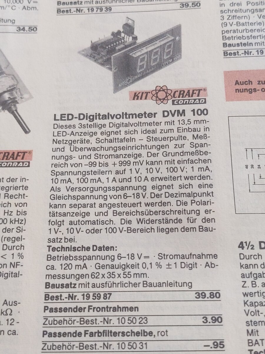
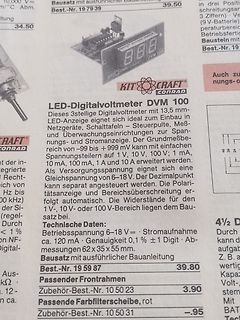
Produktseite eines LED-Digitalvoltmeter Bausatzes
LED-Digitalvoltmeter DVM 100 CONRAD Technische Daten: Betriebsspannung 6-18 V= Stromaufnahme ca. 120 mA Genauigkeit 0,1 % ±1 Digit Abmessungen 62 x 35 x 55 mm. Bausatz mit ausführlicher Bauanleitung 39.80 Best.-Nr. 19 59 87 Passender Frontrahmen Zubehör-Best.-Nr. 10 50 23 3.90 Passende Farbfilterscheibe
-
Thread
Albrecht SW57 Gerät geht nicht mehr an
Stützkondensator fürs IC marode ist. Der Startkondensator hat nominal 220µF. Ein UC3844 startet bei 16V mit 12mA und stoppt bei 10V. Bei 220µF reicht das so 0,1s, wenn keine Nachladung über die Hilfswicklung erfolgt. Über 2x100k wird der 220µF aus 325V dann mit 1,55mA in 0,85s wieder von 10V auf 16V aufgeladen. Das tic tic tic der Startversuche muss bei intaktem 220µF also etwa 1Hz haben. Ist es schneller, fehlt Kapazität. Aber selbst mit <100µF sollte er noch starten können, da bei 50kHz Arbeitsfrequenz bereits nach 20µs nachgeladen würde, wenn sekundär kein Kurzschluss vorliegt
-
Thread
Arduino Nano R4, STMicroelectronics-Bugfix und Marktdaten, ein wenig Lesestoff
with automotive Tier1s with its innovation roadmap in a rapidly expanding MEMS automotive market. MEMS technologies increasingly enable advanced functionalities for safety, electrification, automation, and connected vehicles
Upgrades schwierig sind - 5 V-tolerante 32 Bit-Mikrocontroller fanden die Italiener erst im Renesas RA4M1, der daraufhin auch prompt im Arduino Uno R4 zum Einsatz kam. Populär Formfaktor Nummero zwei ist der Arduino Nano - ihn gibt es nun, wie in der Abbildung gezeigt, ebenfalls mit dem neuen Renesas-Mikrocontroller
-
Thread
mc68360 QUICC Wer hat Erfahrungen damit?
processed on MOS 11's fully qualified 0.55 micron UDR1 technology. Rev L is completely backward compatible with the Rev C.1/E/K devices. These new products will be identified by an 'L' suffix at the end of the part number and will also be
gar nicht erst hat. Ich hab mal auf die schnelle von SCC1 auf SMC1 "umgehäckt", es tut sich nun immerhin schon was am SMTXD1(PB6) Pin, aber richtig funktioneren tut's (leider) noch nicht... (vermutlich was mit den TX-Buffern)
-
Thread
Raspberry Pi Pico für Datenanalyse
sieben Signalleitungen auszuwerten. Eine Signalleitung davon gibt einen Takt vor: Ein logisches Signal 1 (high) für 125 ns gefolgt von einem logischen Signal 0 (low) für 125 ns. Immer bei 1 soll der Zustand aller Leitungen erfasst werden (für jede Leitung gilt ebenfalls 0 oder 1). Zusammen mit den steigenden
Datenpunkt kommt. Würde heissen, dass die Abtastrate doch auch 6 MHz sein kann, da ja immer bei Takt = 1 abgetastet werden muss. Was ich bisher ausfindigmachen konnte: - Es ist auf jedenfall C/C++ notwendig, da mit Micropython maximal circa 55-60 kHz möglich sind. - Benchmarktests haben Signalabtastraten
-
 Bild
Bild
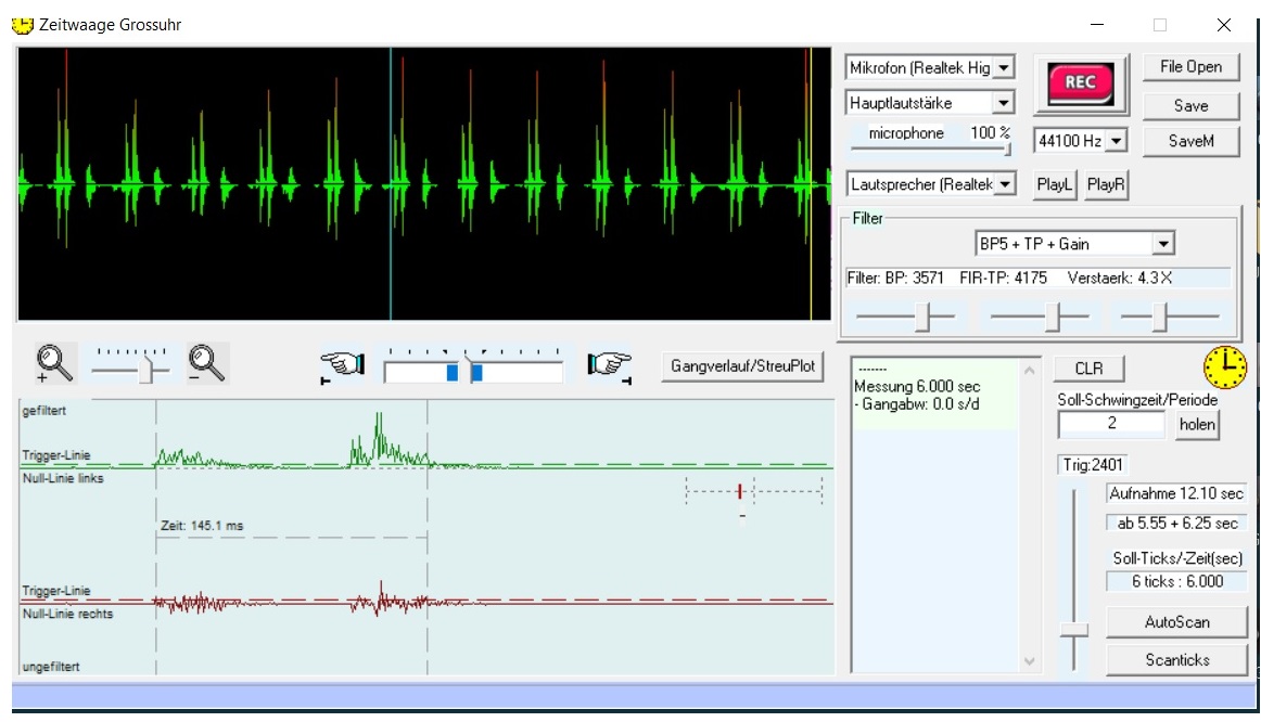
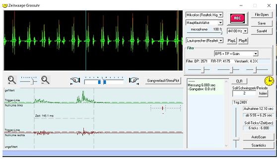
Software zur Zeitwaage-Analyse von Audiosignalen
Lautsprecher (Realtek Filter BP5 + TP + Gain FIR- TP 4175 Verstaerker: 4.3X REC File Open Save SaveM PlayL PlayR CLR gefiltert Trigger-Linie Null-Linie links Zeit: 145.1 ms ungefiltert Trigger-Linie Null-Linie rechts Messung 6.000 sec Gangabw: 0.0 s/d Soll-Schwingzeit/Periode 2 holen Trig: 2401 Aufnahme 12.10 sec ab 5.55 + 6.25 sec Soll-Ticks/Zeit(sec) 6 ticks 6.000 AutoScan Scanticks
-
Thread
Orientierung von Resonatoren
?cate=&partno=CSTCR4M00G55B-R0 Die Frage bleibt natürlich, welchen Hinderungsgrund es geben könnte, die Resonatoren nicht entsprechend der Spezifikation einzubauen ;-)
Datenblatt von Murata zeigen das nicht: https://www.mouser.de/ProductDetail/Murata-Electronics/CSTCR4M00G55B-R0?qs=fPfMK8GXCEJpvxE6N93dow%3D%3D https://www.murata.com/en-global/products/productdetail?partno=CSTCR4M00G55B-R0 Hier ein ähnliches Foto mit deutlich erkennbarer Prägung.
-
 Bild
Bild
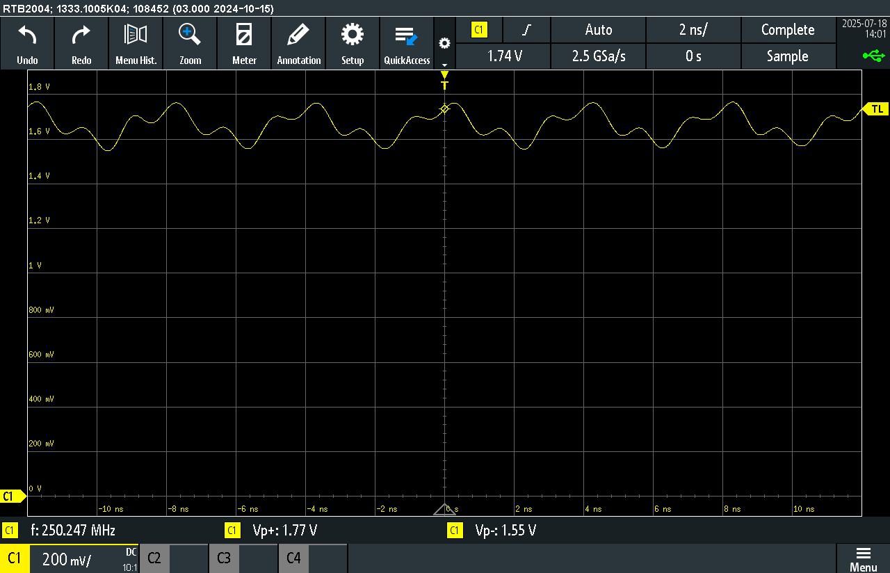
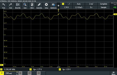
Oszilloskop-Messung einer Wellenform
108452 (03.000 2024-10-15); Undo; Redo; Menu Hist.; Zoom; Meter; Annotation; Setup; QuickAccess; C1; 1.74 V; 2.5 GSa/s; 2 ns/; Complete; 2025-07-18 14:01; Sample; 1.8 V; 1.6 V; 1.4 V; 1.2 V; 1 V; 800 mV; 600 mV; 400 mV; 200 mV; 0 V; -10 ns; -8 ns; -6 ns; -4 ns; -2 ns; 0 s; 2 ns; 4 ns; 6 ns; 8 ns; 10 ns; TL; C1; 250.247 MHz; C1; Vp+: 1.77 V; C1; Vp-: 1.55 V; C1; 200 mV/; DC; C2; C3; C3; C4; Menu
-
Thread
Hameg 203-7 S Nullinie des Komponententester verschoben
Die Spannungen 5V, 12V, -12V habe ich überprüft, 20 mv Abweichung, kein Brumm. Auch die 152 V, 20 mV Spitze Brumm. Wenn Positionsregler für Kanal 1 in Mittenstellung, Strahl in der Mitte. Spannung an Widerstand R2067 hat 92,5 V und lässt sich zwischen 135 und 32 V regeln, der Strahl wandert mit.
und ob auf Y1 oder Y2 (oder auf beide Platten).
-
 Bild
Bild
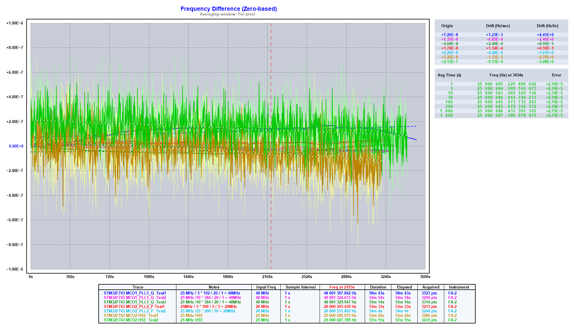
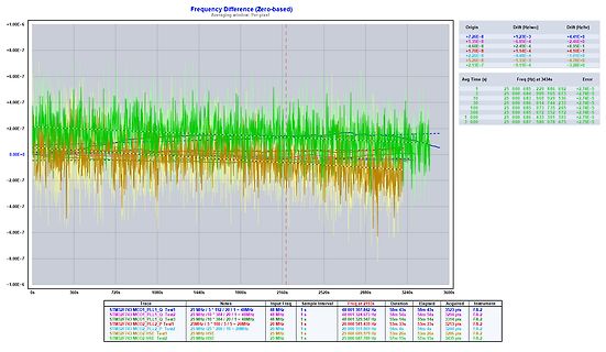
Diagramm der Frequenzabweichung
Interval Freq at 2151s Duration Elapsed Acquired Instrument STM32F434 MC01_PLL_Q Test1 25 MHz / 5192 / 20 / 1 = 48MHz 1 s 48 001 307.842 Hz 58m 43s 3523 pts FA-2 STM32F434 MC01_PLL_Q Test2 25 MHz / 5192 / 20 / 1 = 48MHz 1 s 48 001 329.947 Hz 55m 14s 3314 pts FA-2 STM32F434 MC01_PLL_Q Test3 25 MHz / 5192 / 20 / 1 = 48MHz 1 s 48 001 325.947 Hz 20m 33s 1255 pts FA-2 STM32F434 MC02_PLL_P Test1 25 MHz / 200 / 10 / 5 = 20MHz 1 s 25 000 511.809 Hz 54m 4s 3244 pts FA-2 STM32F434 MC02_HSE Test2 25 MHz 1 s 25 000 6
-
 Bild
Bild
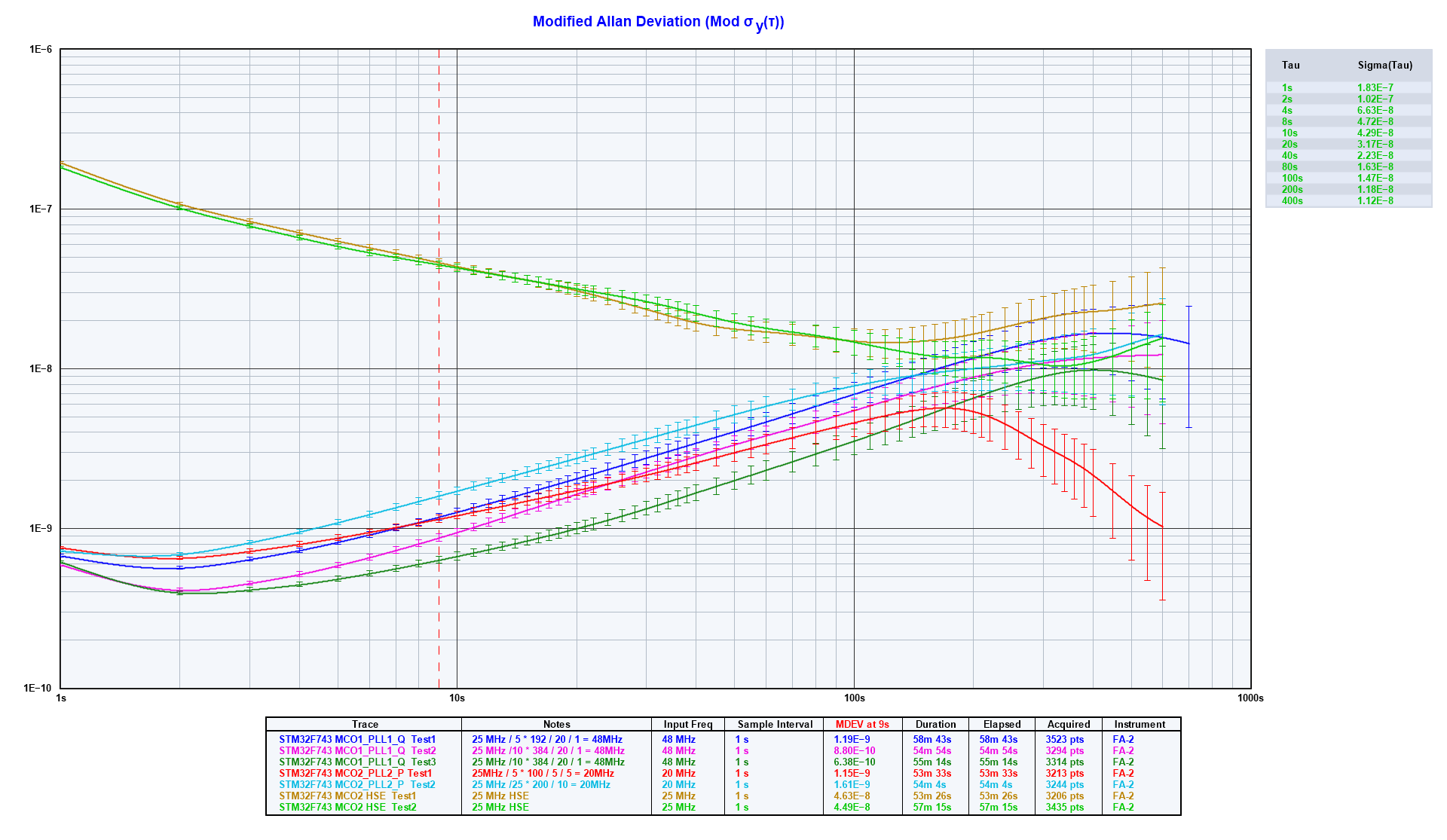
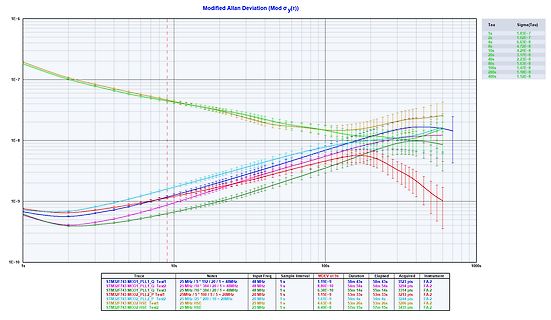
Modified Allan Deviation Diagram
MCO1_PLL1_Q Test 25 MHz / 5* 192 / 20 / 1 = 48MHz 48 MHz 1 s 58m 43s 58m 43s 3523 pts FA.2 STM32F743 MCO1_PLL1_Q Test 25 MHz / 10* 384 / 20 / 1 = 48MHz 48 MHz 1 s 55m 14s 55m 14s 3314 pts FA.2 STM32F743 MCO2_PLL2_P Test 25 MHz / 20* 200 / 15 / 20MHz 20 MHz 1 s 53m 33s 54m 0s 3244 pts FA.2 STM32F743 MCO2_HSE Test 25 MHz 25 MHz 1 s 57m 15s 57m 15s 3435 pts FA.2
-
 Bild
Bild
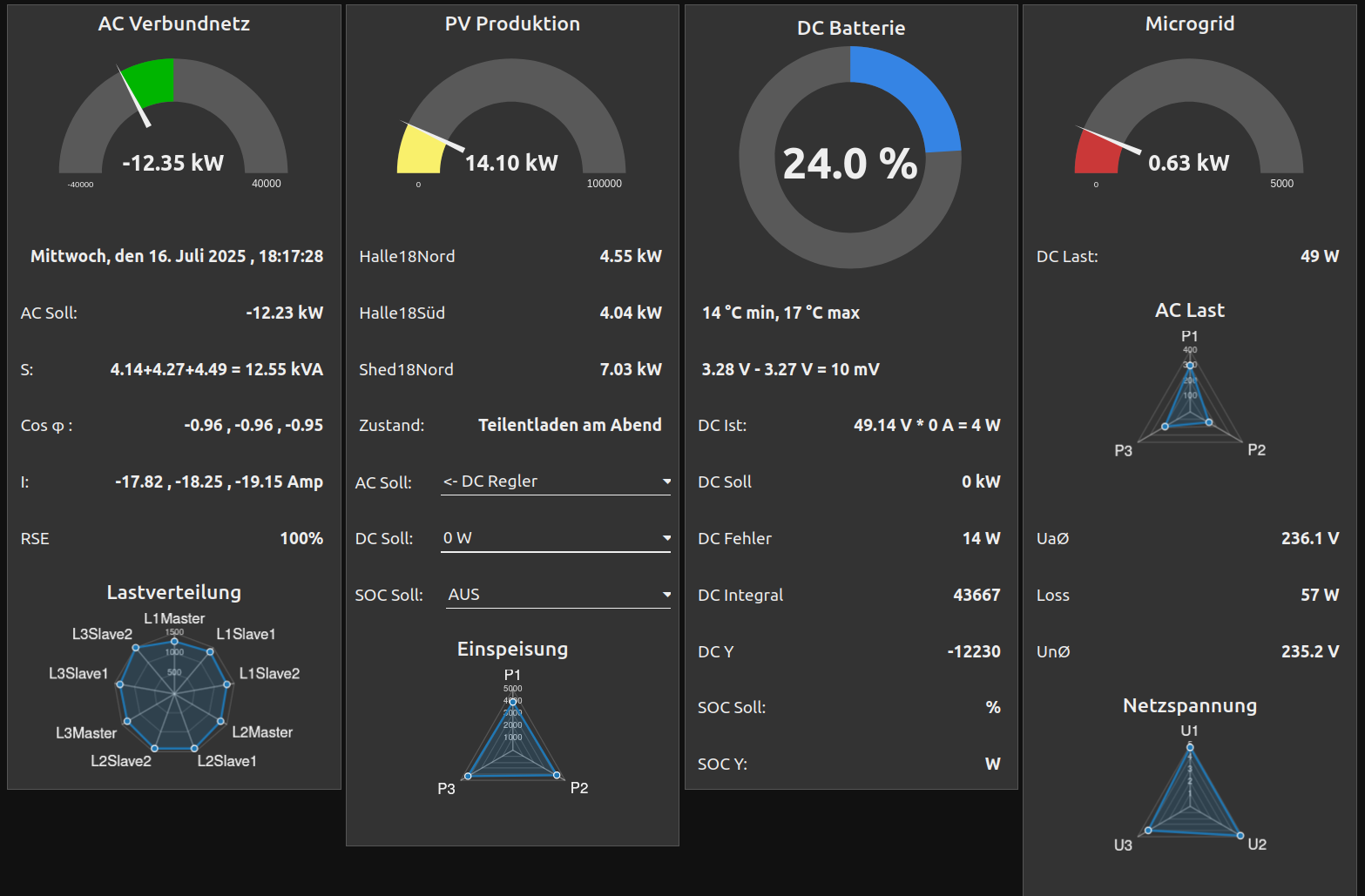
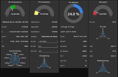
Dashboard einer PV-Anlage und Microgrid-Überwachung
14.10 kW DC Batterie 24.0 % Microgrid 0.63 kW Mittwoch, den 16. Juli 2025, 18:17:28 Halle18Nord 4.55 kW AC Soll: -12.23 kW Halle18Süd 4.04 kW AC Last: 49 W S: 4.14+4.27+4.49 = 12.55 kVA 14 °C min, 17 °C max DC Last: P1 P2 P3 Shed18Nord 7.03 kW 3.28 V - 3.27 V = 10 mV Cos φ: -0.96, -0.96, -0.95 Zustand
-
Thread
LoRa-Parameter
Moin, Ich habe vor, eine LoRa-Kommunikation aufzubauen. Dazu habe ich mir zwei NUCLEO-STM32WL55JC1-Boards und zwei eByte-Module wie im Thread https://www.mikrocontroller.net/topic/578189 besorgt. Beide Systeme funktionieren untereinander einwandfrei. Jetzt würde ich sie gerne "mischen", da die STM32WL55JC1 nicht nur ein Modem sind, sondern auch programmiert werden können (Dual Core). Leider werden die eByte-Module "kryptisch" (in der Art einer LookUp-Table "AirSpeed in bps") konfiguriert, und bei
-
Thread
Welche Pumpe für Brunnen?
Frank M. schrieb im Beitrag #7908024: > Peter G. schrieb im Beitrag #7908018: >> schlechter Erfahrung mit Gardena Tauchpumpen (1x Erdschluss, 1x >> undichtes Gehäuse) bin ich bei Grundfos gelandet. > >
Armin X. schrieb im Beitrag #7909408: > Da lief 1m entfernt, außerhalb des > Grundstücks, ein Bach vorbei... viel Spass beim Starkregen
-
 Bild
Bild
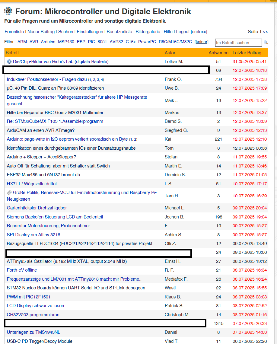
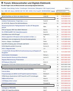
Forum für Mikrocontroller und digitale Elektronik Übersicht
Betreff Autor Antworten Letzter Beitrag Die/Chip-Bilder von Richi's Lab (digitale Bauteile) Lothar M. 51 31.05.2025 05:41 Induktiver Polarisations- Sensor Fragen dazu µC, 40 Pin DL, Quarz an Pins 38/39 identifizieren Uwe B. 734 12.07.2025 17:38 Bezeichnung historischer "Kaltegerätesteck" für ältere HP Messgeräte gesucht Maik.. 24 12.07.2025 15:22 Hilfe bei Reparatur BBC Goertz M2031 Multimeter Markus 13 12.07.2025 13:37 Re: STM32CubeMX F103 Assemblerprogramm Bernd S. 2 12.07.2025 13:09 Arduino: page-write in I2C eeprom verliert sporadisch ein Byte (1, 2) Kai 221 12.07.2025 12
-
 Bild
Bild
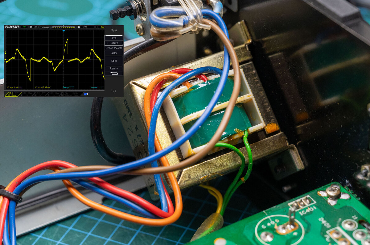
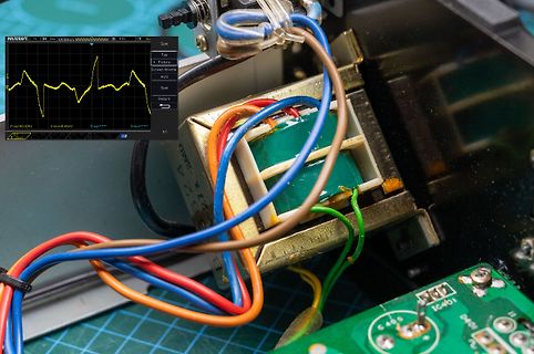
Foto eines Transformators mit Oszilloskop-Anzeige
VOLTCRAFT. H 2M/s 120.00 u/s D 0.0s Spei Typ Picture Screen Invert AUS Spei Return 1/1 Freq:103.02Hz Vmax:6.49mV Vrms:4.55mV
-
Thread
Bezeichnung historischer "Kaltegerätestecker" für ältere HP Messgeräte gesucht
Den habe ich heute aus einer Kabelkiste gerettet, 1,5m Strippe hängt noch dran. Den Schuko hatte schon jemand abgeknipst. Schick mal PN und er soll Dir gehöhren. Dann aber Bild der Kiste ;)
einer Federklemme für den Schutzleiter. Bekommt man auch heute noch: https://www.amazon.de/dp/B0C55JDN4T
-
Thread
Stecher und kein Ende! im Jahr 2025!
Daher gibt es irgendwo auch die ultimative Bedrohung: "El Mosco", ein blutsaugendes Insekt von ca. 1,40m Spannweite, das sich nicht unter 3 Litern frischem Blut pro Opfer zufrieden gibt. Hadmut F. schrieb im Beitrag #7903826: > Jetzt lese ich etwas oel oder seife soll auch gehen? Öl als geschlossene
modulation sidebands (at ±0.5 kHz, ±1.0 kHz, ±1.5 kHz) wingbeat_sidebands = np.zeros_like(f) for i in range(1, 4): # Include ±0.5, ±1.0, ±1.5 kHz wingbeat_sidebands += ( wingbeat_amplitude * np.exp(-((f - (f_center - i *
-
 Bild
Bild
Typenschild eines Transformators
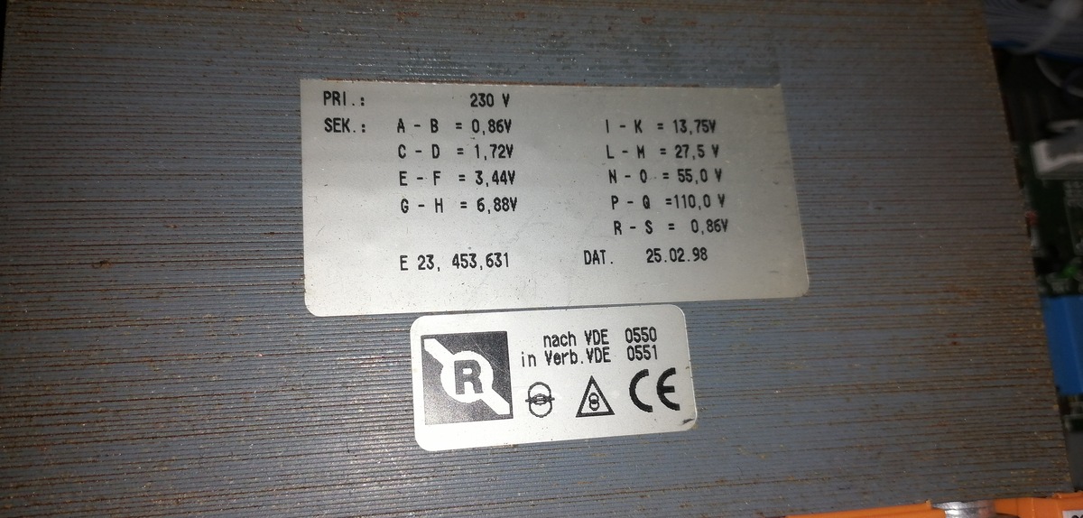
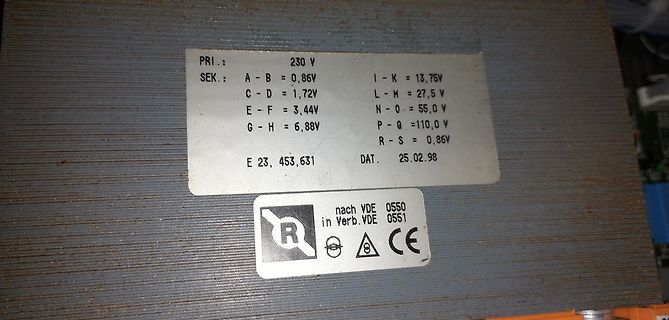
PRI.: 230 V SEK. A - B = 0,86V C - D = 1,72V E - F = 3,44V G - H = 6,88V I - K = 13,75V L - M = 27,5 V N - O = 55,0 V P - Q = 110,0 V R - S = 0,86V E 23, 453,631 DAT. 25.02.98 nach VDE 0550 in Verb. VDE 0551 CE
-
Thread
Klima: Monoblock mit Wasserkühlung
im Raum ungefähr die Hälfte an Strom benötigt. Ein Einrohrgerät hat folgende Bilanz: Wenn 1m³ Luft über den Schlauch ausgeblasen wird mit 45 Grad, wird gleichzeitig über alle Ritzen 1m³ Außenluft mit 30 Grad eingezogen. Zusätzlich wird 1m³ Innenluft angesaugt und 10 Grad kälter wieder in den
Dieter D. schrieb im Beitrag #7903402: > Wenn 1m³ Luft über den Schlauch ausgeblasen wird mit 45 Grad, wird > gleichzeitig über alle Ritzen 1m³ Außenluft mit 30 Grad eingezogen. > Zusätzlich wird 1m³ Innenluft angesaugt und 10 Grad kälter wieder
-
 Bild
Bild
CAD-Layout einer IQ-Expansion Leiterplatte
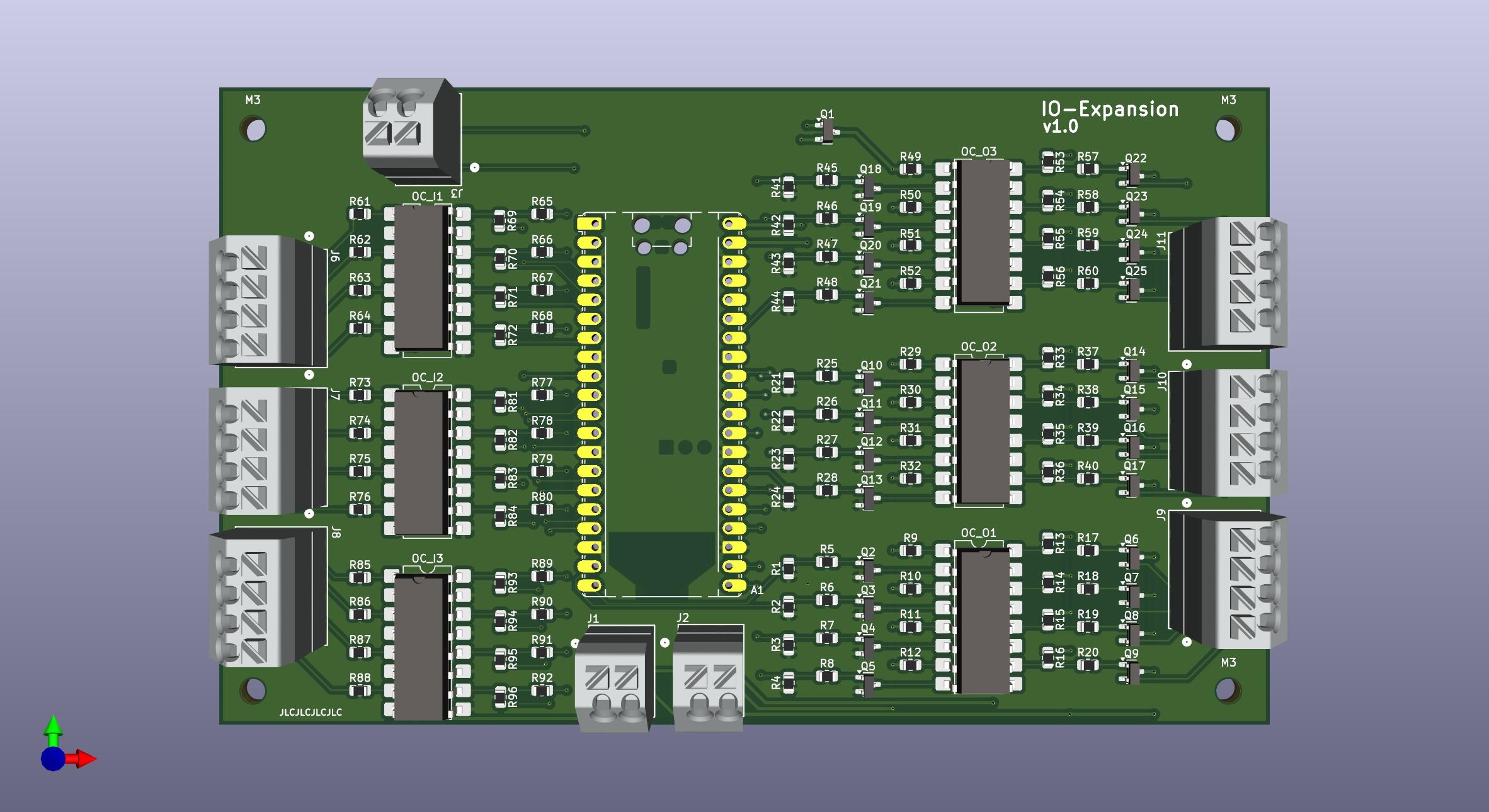
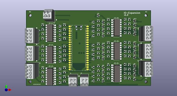
M3 IQ-Expansion v1.0 M3 OC_03 R61 R62 R63 R64 R65 R66 R67 R68 R69 R70 R71 R72 R73 R74 R75 R76 R77 R78 R79 R80 R81 R82 R83 R84 R85 R86 R87 R88 R89 R90 R91 R92 R93 R45 R46 R47 R48 R49 R50 R51 R52 R53 R54 R55 R56 R57 R58 R59 R60 R1 J1 J2 A1 R21 R22 R23 R24 R25 R26 R27 R28 R29 R30 R31 R32 R33 R34 R35 R36 R37 R38 R39 R40 R41 R42 R43 R44 R10 R11 R12 R13 R14 R15 R16 R17 R18 R19 R20 R01 R02 R03 R04 R05 R06 R07
-
 Bild
Bild
Webseite eines Elektronik-Distributors mit Produktinformationen
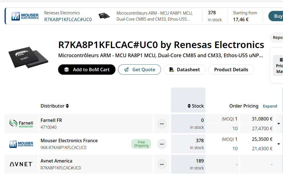
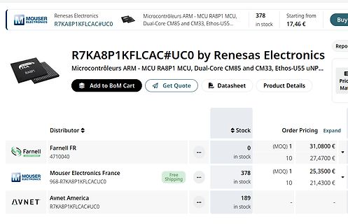
MOUSER ELECTRONICS R7KA8P1KFLCAC#UC0 Renesas Electronics Microcontrôleurs ARM - MCU RA8P1 MCU, Dual-Core CM85 and CM33, Ethos-U55... 378 in stock Starting from 17,46 € Add to BoM Cart Get Quote Datasheet Product Details Distributor Stock Order Pricing Farnell FR 4710040 0 in stock (MOQ) 1 31,0800 € 10 27,4700 € Mouser Electronics France 968-R7KA8P1KFLCACUC0 378 in stock Free Shipping (MOQ) 1 25,3500 € 10 21,4300 € Avnet America R7KA8P1KFLCAC#UC0 189 in stock
-
 Bild
Bild
Blockschaltbild des RA8P1 Mikrocontrollers
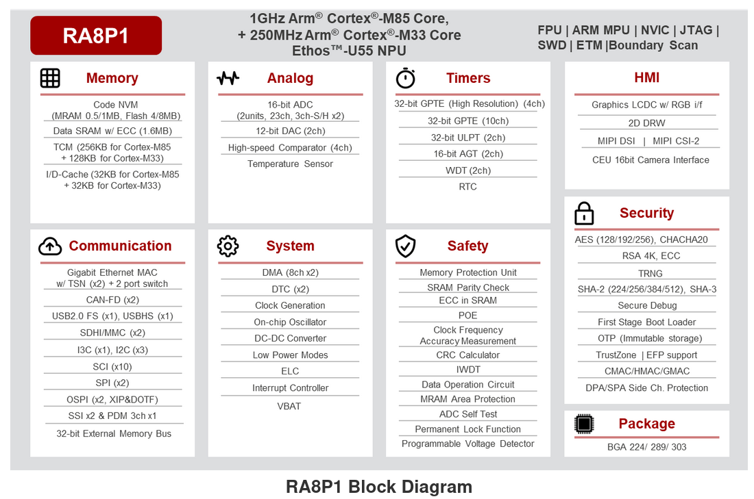
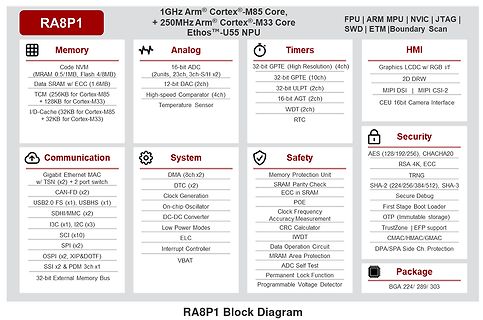
RA8P1 1GHz Arm Cortex-M85 Core, + 250MHz Arm Cortex-M33 Core Ethos-U55 NPU FPU | ARM MPU | NVIC | JTAG | SWD | ETM | Boundary Scan Memory Code NVM (MRAM 0.5/1MB, Flash 4/8MB) Data SRAM w/ ECC (1.6MB) TCM (256KB for Cortex-M85 + 128KB for Cortex-M33) I/D-Cache (32KB for Cortex-M85 + 32KB for Cortex-M33) Analog 16-bit ADC (2units, 2ch (3ch-S/H x2) 12-bit DAC (2ch) High-speed Comparator (4ch) Temperature Sensor Timers 32-bit
-
Thread
Alte Elektroinstallation im Keller FI tauglich machen.
vermutlich sind sie bereits mal erneuert worden. - Alle Kabel, an die man herankommt, erneuern. 50m NYM 3x1,5 kosten ca. 30€. Bei nicht zugänglichen Kabeln prüfen, ob die evtl. durch ein neues Kabel ersetzt werden können. (Kabel verlegen scheint der TE ja zu können, siehe das hinzugekommene 5x 1,5)
vermutlich sind sie bereits mal erneuert worden. > - Alle Kabel, an die man herankommt, erneuern. 50m NYM 3x1,5 kosten ca. > 30€. Bei nicht zugänglichen Kabeln prüfen, ob die evtl. durch ein neues > Kabel ersetzt werden können. (Kabel verlegen scheint der TE ja zu > können, siehe das hinzugekommene
-
Thread
LoRA-Cloud vor Abschaltung, STM32-WLAN-Modul, neue Weltraum-Bauteile uvam
veröffentlichte neue Version 3.1 bietet - wie im unter https://www.phoenixcontact.com/de-de/events-und-news/news/m-guard-secure-cloud-mit-neuer-version-3-1 bereitstehenden Changelog dokumentiert - einige neue Features, die potentiell
integration, device management, and advanced AI capabilities. [/c] ### STMicroelectronics ST67W611M1 – Evaluationsboard verfügbar Die Zusammenarbeit zwischen STMicroelectronics und Qualcomm war auf Mikrocontroller.net in der Vergangenheit bereits mehrfach Thema. Nun gilt, dass das als X-NUCLEO-67W61M1