-
PDF
JE_series.pdf
Actuating Driver. 1.5mm. Shock: Performance (at Initial Value) 2 Endurance...........................1,000m/S . Error Operation....................100 m/S . Contact Resistance.............100 mΩ Max.@1A,6VDC Life Expectancy: Operate Time.......................8 mSec. Max. Mechanical .......................
in „Problem mit Relaiskontakten“ · Mikrocontroller und Digitale Elektronik ·
-
PDF
Relais.pdf
mm standardmäßig waschfest IP 67 • • Spulenspannung 5 V bis max 96 VDC • Ansprechleistung 70 - 90 mW Originalgröße ! • Approbationen in Vorbereitung ABMESSUNGEN 20,2 0 9,8 0 n l n l 1,2 7,62 2,54 k ln l l n + k O O O O m █1 4█ 6█ 8█ , 2 , k 3m m m O O O O , █16 13 11 9█ Bohrunge8 k 2 k 8 - 0,5 x 0,25
in „Strommessplatine wird zu heiß!“ · Analoge Elektronik und Schaltungstechnik ·
-
PDF
128mb_burst_cr1_5_p26z.pdf
Symbol Typ Max Unit Notes Asynchronous random VIN= V CCQ or 0V ICC1 –70 25 mA 5 READ/WRITE chip enabled, –85 22 IOUT = 0 Asynchronous PAGE IC1P –70 15 mA 5, 6, 9 READ –85 12 Initial access, burst ICC2 133 MHz 45 mA 5 READ/WRITE 104 MHz 35 80 MHz 30 66 MHz 25 Continuous burst READ IC3R 133 MHz 40 mA 5 104 MHz 30 80 MHz 25 66 MHz 20 Continuous burst WRITE ICC3W 133 MHz 40 mA 5 104 MHz 35 80 MHz 30 66 MHz 25 Standby current VIN= V CCQ or 0V SB Standard 50 200 µA 7, 8 CE# = V CCQ Low-power 160 (L)
in „Problem mit der Ansteuerung von PSRAM“ · FPGA, VHDL & Co. ·
-
PDF
MT45W8MW16.pdf
Symbol Typ Max Unit Notes Asynchronous random VIN= V CCQ or 0V ICC1 –70 25 mA 5 READ/WRITE chip enabled, –85 22 IOUT = 0 Asynchronous PAGE IC1P –70 15 mA 5, 6, 9 READ –85 12 Initial access, burst ICC2 133 MHz 45 mA 5 READ/WRITE 104 MHz 35 80 MHz 30 66 MHz 25 Continuous burst READ IC3R 133 MHz 40 mA 5 104 MHz 30 80 MHz 25 66 MHz 20 Continuous burst WRITE ICC3W 133 MHz 40 mA 5 104 MHz 35 80 MHz 30 66 MHz 25 Standby current VIN= V CCQ or 0V SB Standard 50 200 µA 7, 8 CE# = V CCQ Low-power 160 (L)
-
PDF
T130-6-DataSheet__1_.pdf
s 105 o A e Eff. Mag. Cross Section 0.698 cm² i n Le- Eff. Mag. Path Length 8.28 cm µ Erms 108 e ( 104 B pk 4.44 Ae N f D V e Eff. Core Volume 5.78 cm³ i i WA - Min. Eff. Window Area 2.93 cm² b B = Peak AC Flux Density (gauss) e e 103 Epk= RMS Sinwave Voltage(volts) a sa - Surface Area 39.8 cm² m A =
-
PDF
T130-6-DataSheet__1___1_.pdf
s 105 o A e Eff. Mag. Cross Section 0.698 cm² i n Le- Eff. Mag. Path Length 8.28 cm µ Erms 108 e ( 104 B pk 4.44 Ae N f D V e Eff. Core Volume 5.78 cm³ i i WA - Min. Eff. Window Area 2.93 cm² b B = Peak AC Flux Density (gauss) e e 103 Epk= RMS Sinwave Voltage(volts) a sa - Surface Area 39.8 cm² m A =
-
PDF
XR2206.pdf
R 10 12 3 R3 XR-2206 10K + 50K 1mF + V 10mF CC V CC 5.1K 5.1K Figure 12. Circuit for Sine Wave Generation with Minimum Harmonic Distortion. (R 3etermines Output Swing - See Figure 3) VCC 1mF 4 1 16 5 15 Mult. >2V F 1 C VCO And 14 6 Sine
in „Funktionsgenerator mit XR2206“ · Analoge Elektronik und Schaltungstechnik ·
-
PDF
XR2206.pdf
R 10 12 3 R3 XR-2206 10K + 50K 1mF + V 10mF CC V CC 5.1K 5.1K Figure 12. Circuit for Sine Wave Generation with Minimum Harmonic Distortion. (R 3etermines Output Swing - See Figure 3) VCC 1mF 4 1 16 5 15 Mult. >2V F 1 C VCO And 14 6 Sine
in „XR2206 Sinus Generator“ · Mikrocontroller und Digitale Elektronik ·
-
PDF
XR2206v103.pdf
R 10 12 3 R3 XR-2206 10K + 50K 1mF + V 10mF CC V CC 5.1K 5.1K Figure 12. Circuit for Sine Wave Generation with Minimum Harmonic Distortion. (R 3etermines Output Swing - See Figure 3) VCC 1mF 4 1 16 5 15 Mult. >2V F 1 C VCO And 14 6 Sine
in „Funktionsgenerator XR2206; Tastverhältins des Rechtecksignals ändern“ · Mikrocontroller und Digitale Elektronik ·
-
PDF
XR2206v103.pdf
R 10 12 3 R3 XR-2206 10K + 50K 1mF + V 10mF CC V CC 5.1K 5.1K Figure 12. Circuit for Sine Wave Generation with Minimum Harmonic Distortion. (R 3etermines Output Swing - See Figure 3) VCC 1mF 4 1 16 5 15 Mult. >2V F 1 C VCO And 14 6 Sine
in „Signalgenerator XR2206 Spanungsgesteuerte Amplitudenverstellung“ · Mikrocontroller und Digitale Elektronik ·
-
PDF
XR2206CP.pdf
R 10 12 3 R3 XR-2206 10K + 50K 1mF + V 10mF CC V CC 5.1K 5.1K Figure 12. Circuit for Sine Wave Generation with Minimum Harmonic Distortion. (R 3etermines Output Swing - See Figure 3) VCC 1mF 4 1 16 5 15 Mult. >2V F 1 C VCO And 14 6 Sine
in „XR2206 - split supply“ · Mikrocontroller und Digitale Elektronik ·
-
PDF
XR2206v103.pdf
R 10 12 3 R3 XR-2206 10K + 50K 1mF + V 10mF CC V CC 5.1K 5.1K Figure 12. Circuit for Sine Wave Generation with Minimum Harmonic Distortion. (R 3etermines Output Swing - See Figure 3) VCC 1mF 4 1 16 5 15 Mult. >2V F 1 C VCO And 14 6 Sine
in „Sinusfrequenz mittels Gleichspannung einstellen XR2206“ · Mikrocontroller und Digitale Elektronik ·
-
PDF
Datenblatt_XR2206.pdf
R 10 12 3 R3 XR-2206 10K + 50K 1mF + V 10mF CC V CC 5.1K 5.1K Figure 12. Circuit for Sine Wave Generation with Minimum Harmonic Distortion. (R 3etermines Output Swing - See Figure 3) VCC 1mF 4 1 16 5 15 Mult. >2V F 1 C VCO And 14 6 Sine
in „Funktionsgenerator mit XR2206 - Ausgangssignale sind unsauber“ · Mikrocontroller und Digitale Elektronik ·
-
PDF
Dokumentation.PDF
IC11 MF03A_N LM4040BIM3X-2.5 Precision Micropower Shunt 1 Voltage Reference, 3-pin SOT-23 IC12 SO16_N M74HC4094M1R 8 Bit SIPO Shift Latch Register (3- 1 State) IC13 SO16_N M74HC4094M1R 8 Bit SIPO Shift Latch Register (3- 1 State) IC14 948E-02_L MC74HC244ADT Octal 3-State Non-Inverting 1 Buffer/Line Driver/Line Receiver IC15 M14A_N CD4066BCM Quad Bilateral Switch 1 L1 4.7uH MSS1260 Inductor Inductor 1 L2 10uH INDC2012M Inductor 1 R1 0.1 RES_2512 Res2 CRL2512-JW-R100ELF CRL2512-JW-R100ELF 1 R2 0.1 RES_2512 Res2 CRL2512-JW-R100ELF
-
PDF
1.5KE400CA.pdf
Voltage BR T (Note 2) @ I Current Variation @ V R pp of VBR (UNI) (BI) VRWM (V) Min (V) Max (V) It(mA) R (mA) V CV) PP (A) %/°C 1.5KE6V8A 1.5KE6V8CA 5.80 6.45 7.14 10 1000 10.5 143.0 0.057 1.5KE7V5A 1.5KE7V5CA 6.40 7.13 7.88 10 500 11.3 132.0 0.061 1.5KE8V2A 1.5KE8V2CA 7.02 7.79 8.61 10 200 12.1 124.0
in „Ersatztypen für Diode“ · Mikrocontroller und Digitale Elektronik ·
-
PDF
M12021PB_SM_PANASONIC_EN.pdf
■ erv1ce CRT Data Display MODEL M-900 X X X Series Chassis No. YOSA Chassis Family No. 9Y08 MODEL M-1200 X X X Series Chassis No. YOS Chassis Family No. 12 YOS Model Model Model M-9004NA , M9009NA M-K12004NB, M-K12001NB M-12004NB M-9001NA, M-9009A Direct Drive Input Kit Type Direct Drive Input Direct Drive Input Model Model M-C12004N, M-C12001N M-C9004N, M-C9001N M-C12009N Compsite Video Input Compsite Video lnput Model M-12021PB, M-12021NB
in „CRT Monitor gegen VGA Monitor tauschen“ · Analoge Elektronik und Schaltungstechnik ·
-
PDF
M12021PB_SM_PANASONIC_EN.pdf
■ erv1ce CRT Data Display MODEL M-900 X X X Series Chassis No. YOSA Chassis Family No. 9Y08 MODEL M-1200 X X X Series Chassis No. YOS Chassis Family No. 12 YOS Model Model Model M-9004NA , M9009NA M-K12004NB, M-K12001NB M-12004NB M-9001NA, M-9009A Direct Drive Input Kit Type Direct Drive Input Direct Drive Input Model Model M-C12004N, M-C12001N M-C9004N, M-C9001N M-C12009N Compsite Video Input Compsite Video lnput Model M-12021PB, M-12021NB
in „Heidenhain Monitor BE 212 für TNC 351“ · Analoge Elektronik und Schaltungstechnik ·
-
PDF
LM3409__LM3409HV.pdf
0 < CC < 20 mA VCC-UVLO VCC under voltage lockout V CCincreasing 3.73 V threshold VCC-HYS VCC UVLO hysteresis V CCdecreasing 283 mV I V regulator current limit 30 45 mA CC-LIM CC OFF-TIMER AND ON-TIMER VOFT Off-time
in „High Power LED Stroboskop“ · Mikrocontroller und Digitale Elektronik ·
-
PDF
211101-Espressif_ESP32_Schema.pdf
0 1 8 2 9 105 1025 1 0 5 1 0 2 6 11 2 8 1017 1 0 2 7 1 2 1026 1 0 1 7 2 7 1016 1027 1 0 1 6 13 2 6 104 14 1014 2 5 100 l012uOSSüüSSoO lOO |.GND C D CO CJ)O ( N CO ■c f CN CNC N( N C NC N J2 U 2 G N D B O O T O P T I O N R 2 J O O R M T M S MTMS -j; C N CO Q o ■Ra/TTtfÖR mtdT Q Q Q Q C N M T D I O R M T C K CO CO O o CO CO O MTCK -4 M T D O — RSy^gO MR TDO J T A G Figure 2: ESP-WROOM-32 Peripheral Schematics N o t e : The MTDI should be kept at low electric level. Espressif Systems 1 3 http ://www. espressif. com
in „ESP32 MicroPython Brownout detector was triggered“ · Mikrocontroller und Digitale Elektronik ·
-
PDF
ca3080-a.pdf
CA3080, CA3080A E P RO DU CT E NT O BS OL ET D RE PLA CE M er at O M M EN DE up portC ent /tc N O R DatarSheetnical S .ntersilcom August 2004 FN475.6 c ontacto u S I or ww w 1-888-INTE R 2MHz, Operational Transconductance Features Amplifier (OTA) Slew Rate (
in „Dimensionierung eines OTA in CMOS-Technologie“ · Analoge Elektronik und Schaltungstechnik ·
-
PDF
nRF2401rev1_1.pdf
current in power down 400 nA Receiver operation IVDD Supply current one channel 250kbps 18 mA IVDD Supply current one channel 1000kbps 19 mA I Supply current two channels 250kbps 23 mA VDD IVDD Supply current two channels 1000kbps 25 mA RX SENS Sensitivity at 0.1%BER (@250kbps) -90 dBm RX SENS
in „Externe Antenne für Funkmodul TRW24G“ · HF, Funk und Felder ·
-
PDF
TDA8920B.pdf
]- - 150 mV V OO(BTL)(mute)mute BTL output offset voltage - - 21 mV [4] V OO(BTL)(on) operating BTL output offset voltage - - 210 mV Stabilizer output; pin STABI V o(stab) stabilizer output voltage mute and operating
in „Schaltnetzteil im Audioverstärker defekt?“ · Analoge Elektronik und Schaltungstechnik ·
-
PDF
6800_Instruction_Set.PDF
6800 Instruction Set n l r t I a y t t h e s r C c n t x n e g t g d o c s A D B O H M E R B l A M C D 0 00000000 000 00 ! 1 00000001 001 01 NOP 1 2 No Operation 2 00000010 002 02 ! 3 00000011 003 03 ! 4 00000100 004 04 ! 5 00000101 005 05 ! 6 00000110 006 06 TAP AF 1 2 Transfer A to Status
in „Neues aus der KI“ · Offtopic ·
-
 Bild
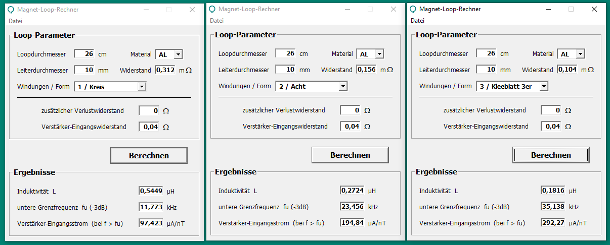
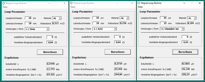
Drei Fenster eines Magnet-Loop-Rechners
Magnet-Loop-Rechner Datei Loop-Parameter Loopdurchmesser 26 cm Material AL Leiterdurchmesser 10 mm Widerstand 0,312 mΩ Windungen / Form 1 / Kreis zusätzlicher Verlustwiderstand 0 Ω Verstärker-Eingangswiderstand 0,04 Ω Berechnen Ergebnisse Induktivität L 0,5449 µH untere Grenzfrequenz fu (-3dB) 11,773 kHz Verstärker-Eingangsstrom
in „Mini Loopantenne mit NE592N14“ · HF, Funk und Felder · · Screenshots
-
PDF
optokoppler_66156.pdf
(see Note 2) ................................300mW Average Forward Input Current ..........................................................................................................................................50mA Reverse Current (LED)....
in „Input current Low/ Hig“ · Mikrocontroller und Digitale Elektronik ·
-
PDF
LC4104C.pdf
to O160 1 3 kΩ IDD VDD = 2.7 to 5.5 V 5.0 mA VDD = 2.7 to 5.5 V,DDH = 32 V , 2.0 mA Current drain DDH V = 5 V ± 10%, V = 36 V DD DDH 2.0 mA I *3 500 µA ST Note: 1. V is the voltage applied for an on output, V0 = V, V2 = 18/20 (V – V ), V3 = 2/
in „Display von Pollin - Datenblatt - Ansteuerung“ · Mikrocontroller und Digitale Elektronik ·
-
Datei
imgres.htm
13==e,e=(0==F[q]%e||h)&&!!f)}e&&(c="clickkey")}q=b.srcElement||b.target;e=R(c,b,q,"",null);b.path?(M.j=b.path,M.g=0,M.i=this,M.l=!1,f=M):f=K(q,this);for(;h=f.h();){var m=h;var g=m;h=c;var p=g.__jsaction;if(!p){var u=null;"getAttribute"in g&&(u=g.getAttribute("jsaction"));if(u){p=t[u];if(!p){p={};for
in „Anschlussplan Thermoschalter / Electrolux Herd Thermo-Schalter 387207902“ · Haus & Smart Home ·
-
PDF
bc847_p.pdf
as a function collector current; typical values of collector current; typical values mgt729 mgt730 104 1200 VBEsat V CEsat (mV) (mV) 1000 (1) 3 10 800 (2) 600 (3) 102 400 (1) (3)(2) 200 10 −1 2 3 0 −1 2 3 10 1 10 10 10 10 1 10 10 10 C (mA) IC(mA) IC B = 20 IC B = 10 (1) Tamb = 150 °C (1) T amb= −55 °
-
PDF
usb-footswitch.pdf
Pre-programmed functions to customers requCustomer with Internal switches. ❖ Dimensions : 141mm x 104mm x 45mm ❖ Any Keyboard key (or combination of up to four keys) may be emulated. ❖ Multi keystroke functions available on each switch. e.g. Ctrl / Alt / Del !!! ❖ Black is standard colour. Other colours available ( OEM quantities only ) ❖ 2.5M cable length available as standard. Up to 3M fitted cable available . ❖ 5M Active extension cables must be used as USB 1.1 is low speed and robust. ❖ Multiple footswitches and hand controls may be connected
in „Verbesserungsmöglichkeiten gängiger Layoutsoftware - National Instruments“ · Platinen ·
-
PDF
irl7486mpbf-936689.pdf
)typ. 1.5m max @ V = 4.5V 2.0m Benefits GS Optimized for Logic Level Drive ID (Silicon Limited) 209A Improved Gate, Avalanche and Dynamic dv/dt Ruggedness Fully Characterized Capacitance and Avalanche
in „Reparatur Makita XWT08Z (DTW1002Z)“ · Analoge Elektronik und Schaltungstechnik ·
-
 Bild
Solar MPPT Laderegler mit LED Display
+ IN MPPT LED CV 024 T 04 024 T 104 011 M 503 129 M + KEY VBE V1/V2 A/P
in „Kompakter MPPT für 100 W Solarmodul“ · Haus & Smart Home · · Platinenfotos

-
 Bild
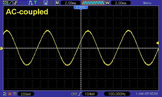
Oszilloskop-Screenshot einer Sinuswelle
AC-coupled 0.000s 2.00ms 2.00ms Menu 20 200mV CH1 104mV 100.000Hz 1-Jan-09 00:05
in „Physikprojekte“ · Offtopic · · Oszi-Bilder
-
PDF
ALC5000M_KM_G_111208.pdf
1 2 2 2 1 2 2 D 7 8 6 3 5 4 4 2 3 9 0 1 0 0 0 1 0 M R R 0 1 0 1 NQ 1 7 1 K 1 R 0 R 7 0 K 7 4 1 6 0 D C NQM 0 3 C C 5 4 2 2 L S1 7 4 1 M5 R104 8 D S 2 S 2 10R M 0 M 0 D n D n C 7 1 7 1 C C C 0 R 3 R 2 5 1 1 1 8 C 1 8 5 1 5 1 S 0 9 6 S1 3 6 1 6 1 M + M0
in „ELV ALC 5000 - Softwarefehler“ · Mikrocontroller und Digitale Elektronik ·
-
PDF
Reference_Design_Dimming_Ballast_Control.pdf
+ B U R S RMAX D V M C C P C V RMIN CMIN H C D O C D M RFMIN 8 7 6 5 4 3 2 1 I I P F M M D P V D R H B H M N A M H C C A N X O 2 L 5 S L C V H 9 C T S C O M C V V O 2 1 D S C B S 0 C 9 1 1 1 C 1 1 1 6 0 1 2 C 3 4 5 1 L M
in „Leuchstoff Röhre Dimmer Neon“ · Mikrocontroller und Digitale Elektronik ·
-
PDF
Sp3A-DSP-1800A-Starter-Schematic-Rev1.pdf
Serial Yes Open Open Open Closed EXP2_SE_IO_15 IP_2_VREF_2 Y16 PO_RESET# 16 7 8 EXP2_SE_IO_16 FPGA_M2 5 6 Slave Serial No Open Open Open Open AC4 FPGA_M1 3 JP9 4 EXP2_SE_IO_18 IO_L01p_2_M1 AD4 FPGA_M0 1 2 Master SPI Yes Closed Closed Open Closed IO_L01n_2_M0 Y7 EXP2_SE_IO_20 IO_L02p_2_M2 AA7 Master
in „Schematics von Spartan 3A-DSP 1800 Board“ · FPGA, VHDL & Co. ·
-
PDF
Gewinde.pdf
mm mm M2 x 0,2 1,870 1,756 1,783 M2,5 x 0,25 2,338 2,193 2,229 M3 x 0,35 2,773 2,571 2,621 M4 x 0,5 3,675 3,387 3,459 3,5 M5 x 0,5 4,675 4,387 4,459 4,5 M6 x 0,75 5,513 5,080 5,188 5,25 M8 x 0,75 7,513 7,080 7,188 M8 x 1 7,350 6,773 6,917 7 M10 x 0,75 9,513 9,080 9,188 9,25 M10 x 1 9,350 8,773 9,350 M12 x 1 11,350 10,773 11,350 M12 x 1,25 11,188 10,466 11,188 M16 x 1 15,350 14,773 15,350 M16 x 1,5 15,026 14,160
-
PDF
SED1565.pdf
. 136~273 47 m × 85 m PAD No. 274 73 m × 85 m PAD No. 275 85 m × 73 m PAD No. 276~308 85 m × 47 m PAD No. 309 85 m × 73 m Bump Height 17 m (Typ.) Chip Thickness 625 m 8–4 EPSON SED1565 Series SED1565* ** Pad Center
in „Pollin 128x64 GLCD : Bild verzerrt“ · Mikrocontroller und Digitale Elektronik ·
-
Datei
sine_light4.asm
leftmost port) ; No Resistor used here ; --- insert GPL here --- Wiebel, 2007 ; .NOLIST .include "m169def.inc" .LIST .CSEG .def temp = r16 .def pow = r17 .def ACount = r18 .def BCount = r19 .def PCount = r20 .def state= r21 .def speed = r22 .def light = r23 .def table = r0 ; Z points here, readout
in „Sinus mit PWM und tiny2313 - suche Codebeispiel“ · Mikrocontroller und Digitale Elektronik ·
-
 Bild
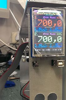
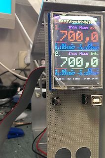
Display eines MassSpectroMeter Messgeräts
MassSpectroMeter 1. show Mass ext 700,0 + m1 - b1 0,1234567 -0,1234567 2. show Mass int. 700,0 + m2 - b2 0,1234567 -0,1234567 13:44 Mar 6 2015 x= 104 y= 08
in „Suche ein TFT (smart) mit Frame für Arduino und co.“ · Mikrocontroller und Digitale Elektronik · · Fotos
-
 Bild
Display eines MassSpectroMeter Messgeräts
MassSpectroMeter 1. show Mass ext 700,0 + m1 - b1 0,1234567 -0,1234567 2. show Mass int. 700,0 + m2 - b2 0,1234567 -0,1234567 13:44 Mar 6 2015 x= 104 y= 08
in „Projekt Labornetzteil 2024“ · Projekte & Code · · Fotos
-
PDF
MapCom.pdf
47R R484 C16160 GND 47k MICNCNP39103GND GND PI42043MICPC PIS103MICN MICP PIS1042 470R 62 SPNPN PIS104SPN SPP PIS1041SPSP C R2 C Siemens m20 GND GND P3P3 CCVCC PIP3011 CO1710 CCRSTS PIP3022 L2L C181 U171 LP2980-3.0 CCCLK PIP303 SPEAKER_PIL201 PIL20P2IR49PIR4902 PIC1801 PIC1802 VCVCC PIU1701 PIU1705CC
in „[V] Weiterer M8, GPS, GSM Siemens M20, ATmega128“ · Markt ·
-
PDF
AND9388-D.PDF
1005(0402) ROHM MCR01MZPJ512 R53−55 3 Thick film Resistor 100 kW, 1/10 W ±5% 1005(0402) ROHM MCR01MZPJ104 C7 1 Pad Only C14, C15 2 Ceramic multilayer Capacitor 0.01 mF, 50 V ±5% 1608(0603) TDK CGA3E2NP01H103J080AA C8, C11, C12 3 Ceramic multilayer Capacitor 4.7 mF, 25 V ±10% 3225(1210) TDK CGA6P3X8R1E475K250AB C9, C10 2 Ceramic multilayer Capacitor 1.0 mF, 25 V ±10% 3216(1206) TDK CGA5L2X8R1E105K160AA C27, C29 2 Ceramic multilayer Capacitor 0.1 mF, 50 V ±10% 2012(0805) TDK CGA4J2X8R1H104K125AA C28, C30−31 3 Electrolytic Capacitor 47 mF, 35 V ±20% 3 ×
in „BLDC LV8907 via SPI einstellen funkt nicht..“ · Mikrocontroller und Digitale Elektronik ·
-
PDF
Schaltplan_RW.pdf
GNDB B 3 LO G E P D2 SAONS66402 1 10 SG PG 16 0 1N4148 R10 S GNDB GNDB 3 10k 0 DNP R101 P GNDPWR R10R104 0 A GND GND C C B B Q101 GND C E BC818 C GND VIN VIN VIN VIN V R102 E 1M k 3 4 6 n 1 R 1 R 1 1 C C101 C7 C8 C9 X k7 2.2u,50V 150u,35V 150u,35V 150u,35V - 6R GND GND R12 C 0.01 F 1 1 k6 E 3 2R GND L
in „Verbindung einer Leuchtdiode mit einem Fototransistor erzeugen“ · Analoge Elektronik und Schaltungstechnik ·
-
PDF
doc4779atr2406.pdf
d Pin 1 R X PU_TRX T Pin 27 i > 40 µs > 40 µs m > 50 µs n g D a TX_DATA Data g Pin 29 a m 3W_CLK Preamble (1-0-1-0) Pin 30 p ( 16/25 bits 16 bits 3W_DATA R > 200 µs > 200 µs Pin 31 t a 3W_ENA i Pin 32 S nOLE Pin 26 REF_CLK REF_CLK REF_CLK Pin 2 >
in „Gauss Anpassung Register“ · Mikrocontroller und Digitale Elektronik ·
-
 Bild
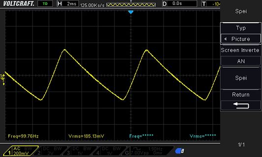
Oszilloskop-Messung eines Sägezahn-Signals
VOLTCRAFT. H 2ms 125.00Ks/s D 0.0s T -104 Spei Typ Picture Screen Inverte AN Spei Return 1 200mV Freq=99.76Hz Vrms=185.13mV Freq=***** Vrms=***** 1/1 2 2V 3 1V 4 1V G 7.00Vpp 1.90Hz 0mv
in „Nakamichi 482 Brummspannung“ · Analoge Elektronik und Schaltungstechnik · · Oszi-Bilder
-
PDF
REGELTRAFO_ESS_104_de_en.pdf
Parallelschaltungvon2Einzeltransformatorenhintereinanderangeordnet/parallelconnectionof2singletransformers ESS 9340 37,0 34,0 420 210 26 270 M8 126 33,0 ESS 9380 42,0 38,0 ESS 3340 39,0 34,0 ESS 4180 20,0 18,0 253 231 450 8 180 Bolzen 0..35 35,0 ESS 9480 53,0 48,00 ESS 3440 50,0 44,0 ESS 4230 25,0 23,0 450 M10 210 26 300 M8 126 38,0 Parallelschaltungvon3Einzeltransformatorenhintereinanderangeordnet
-
PDF
ADW1_Relais.pdf
68°F) power (at 20°C 68°F) Set coil Reset coil Set coil Reset coil Set coil Reset coil 3V DC 133.3mA 133.3mA 22.5Ω 22.5Ω 5V DC 80.0mA 80.0mA 62.5Ω 62.5Ω 6V DC *80%V or less of *80%V or less of 66.7mA 66.7mA 90 Ω 90 Ω 110%V of nominal nominal voltage nominal voltage 400mW 400mW 9V DC (Initial) (Initial) 44.4mA 44.4mA 202.5Ω 202.5Ω voltage 12V DC 33.3mA 33.3mA 360 Ω 360 Ω 24V DC 16.7mA 16.7mA 1,440 Ω 1,440 Ω *Square, pulse drive 2. Specifications Specifications Characteristics Item Standard type Inrush type
in „Inkompetente Relais-Hersteller?“ · Analoge Elektronik und Schaltungstechnik ·
-
PDF
sct2932.pdf
Efficiency vs. Input Voltage at Various LED Cascaded Number Efficiency vs. input voltage @L=OUT384mA Efficiency vs. input voltage @L=OUT384mA Efficiency vs. input voltage @L=OUT769mA Page 8 of 27 SCT2932 1.5A LED Driver with Internal Switch Efficiency vs. input voltage @L=68uH, I =769mA OUT Efficiency
in „Suche geeigntes Netzteil für 3x LED-Downlights Konstanstrom 250mA“ · Haus & Smart Home ·
-
PDF
mic920.pdf
-15 Av = 2 0.05 Av =–1 -20 RF= RI= 475Ω -20 R+ = R = 475Ω 0.0-40 -20 0 20 40 60 80 100 -25 I -25 1M+6 110M6 1100M0E+6 11M6 110M6 1100M00E+6 TEMPERATURE°(C) FREQUENCY (Hz) FREQUENCY (Hz) Closed-Loop Gain Closed-Loop Gain Open-Loop Gain vs. Frequency vs. Frequency vs. Frequency 50 50 50 )40 )40 40 V±
in „LTspice - OPAmp Modell aus Datenblatt“ · Analoge Elektronik und Schaltungstechnik ·