-
Datei
EEPROM.c
#include <stdint.h> #include "stm32f10x_i2c.h" #include "stm32f10x_rcc.h" #include "I2C.h" void delay() { for (volatile uint16_t del = 0; del < 25000; del++) ; } void main() { uint8_t burst_data_write[5] = {0x24, 0x48, 0x52, 0x59, 0x73}, burst_data_read[6] = { 0 }; uint8_t single_data_read = 0; I2C_init(I2C2, 100000); delay(); I2C_single_write(I2C2, 0xA0, 0x20, 0x15); delay(); I2C_burst_write(I2C2, 0xA0, 0x11, 5, burst_data_write); delay(); single_data_read = I2C_single_read
in „STM32F103RFT6 I2C2 keine Funktion“ · Mikrocontroller und Digitale Elektronik ·
-
PDF
STM32F4-BASE_BRD.pdf
1 SV1 10 10 SV5 1 1 4VS 01 1 1 1 N 6 R R8 O SV6 J R9 C JP7 JP15 2 X2 2 MCU1 C20 C18 2 4 3 1 C C 1 R10 3 3 0 C22 C U1 2 U2 R11 J S 1 C 1 J C1 S JP11 1 1 1 1 1 D1 1 3 4 2 C C C C C JP5 3 4 C2X1 4 1 7 1 9 P 4 R R R C R R2 C6 C J J X 2 3 L 8 C93
in „STM32F407 (100pin) Basisboard - Review bitte“ · Mikrocontroller und Digitale Elektronik ·
-
Datei
pinouts.txt
################################################################## STM8S103F3P6 Pinout ################################################################## ------------ UART1_CK / TIM2_CH1 / PD4 | 1 20 | PD3 / AIN4 / TIM2_CH2 / ADC_ETR UART1_TX / AIN5 / PD5 | 2 19 | PD2
in „STM8S Minimumboard + SSD1306 OLED Display“ · Projekte & Code ·
-
Datei
xpt2046.c
xpt2046.c * * Created on: Jul 21, 2018 * Author: Dimitris Tassopoulos */ #include "xpt2046.h" #include "stm32f10x_gpio.h" #include "stm32f10x_exti.h" #define XPT2046_IRQ_PIN GPIO_Pin_8 #define XPT2046_IRQ_PORT GPIOA static struct dev_spi gspi; static struct dev_spi * m_spi = &gspi; static struct touch_point
in „C Code Verständnis Problem“ · Mikrocontroller und Digitale Elektronik ·
-
PDF
STM32F429_V1.2.pdf
GND GND STM32F429IGT6 GND SDIO_DPIU20140 PC10 PH10 P I U 2 0 8 82 3V3 SDIO_CPIU20141 PC11 PH11 P I U 2 0 8 93 IS42S16400J GND PC13 P I U 2 0 812 PH12 PIU20128DC_G2 OSC32_IN 9 PC13 PH13 129 DCMI_D4 3V3 BOOT0 COR
in „Hat jemand Erfahrungen mit diesem Board auf Ebay.“ · Mikrocontroller und Digitale Elektronik ·
-
Datei
main.c
neccessary CAN_DeInit(CAN1); } /** * send data via can bus */ int can_send(int message_id, char data[8]) { // send message via can CanTxMsg message; uint8_t mailbox; uint8_t status; int i; message.StdId = message_id; message.ExtId = 0; message.RTR = CAN_RTR_DATA; message.IDE = CAN_ID_STD; message.DLC = 8; for (i = 0; i < 8; i++) { message.Data[i] = data[i]; } // transmit and hope to get a free mailbox mailbox = CAN_Transmit(CAN1, &message); if(mailbox == CAN_NO_MB) { return -1; } // wait until message
in „STM32F1 sendet kein CAN“ · Mikrocontroller und Digitale Elektronik ·
-
Datei
pcf8574.c
#include <stm32f10x.h> #include <stm32f10x_i2c.h> #include "pcf8574.h" #define PCF8574_I2Cx_RCC RCC_APB1Periph_I2C1 #define PCF8574_I2Cx I2C1 #define PCF8574_I2C_GPIO_RCC RCC_APB2Periph_GPIOB #define PCF8574_I2C_GPIO
in „STM32 I2C Probleme mit PCF8574“ · Mikrocontroller und Digitale Elektronik ·
-
Datei
kk_bb.c
wait _delay_ms(1000) #define wait10 do{_delay_ms(3333);_delay_ms(3333);_delay_ms(3333);}while(0) //2^8 = 256 //2^16 = 65.536 //2^32 = 4.294.967.296 //2^64 = 18.446.744.073.709.551.616 #define u8 uint8_t //255 #define u16 uint16_t//65.535 #define u32 uint32_t// 4.294.967.295 #define i8 int8_t //+-127 #
in „Problem FatFS + SPI“ · Mikrocontroller und Digitale Elektronik ·
-
Datei
startup_stm32f20x.S
through EXTI Line */ .word OTG_FS_WKUP_IRQHandler /* USB OTG FS Wakeup through EXTI line */ .word TIM8_BRK_TIM12_IRQHandler /* TIM8 Break and TIM12 */ .word TIM8_UP_TIM13_IRQHandler /* TIM8 Update and TIM13 */ .word TIM8_TRG_COM_TIM14_IRQHandler /* TIM8 Trigger and Commutation and TIM14 */ .word TIM8_
in „STM32 FreeRTOS Projekt (Makefile - GCC)“ · Projekte & Code ·
-
Datei
GLCD.h
define R133 0x85 #define R134 0x86 #define R135 0x87 #define R136 0x88 #define R137 0x89 #define R139 0x8B #define R140 0x8C #define R141 0x8D #define R143 0x8F #define R144 0x90 #define R145 0x91 #define R146 0x92 #define R147 0x93 #define R148 0x94 #define R149 0x95 #define R150 0x96 #define R151 0x97
in „STM32 24Bit Bmp nach 565RGB Format“ · Mikrocontroller und Digitale Elektronik ·
-
Datei
usart.h
********** #pragma once #include <clock.h> #include <ioreg.h> #include <static_assert.h> #include "stm32f4xx.h" #include <iopins.h> #include <pinlist.h> #include <stddef.h> #include <dma.h> #include <dispatcher.h> namespace Mcucpp { class UsartBase { public: enum UsartMode { DataBits8 = 0, DataBits9
in „STM32 / C++: Initialisierung von Memberobjekten einer Klasse“ · Mikrocontroller und Digitale Elektronik ·
-
Datei
startup_stm32f4xx.S
through EXTI Line */ .word OTG_FS_WKUP_IRQHandler /* USB OTG FS Wakeup through EXTI line */ .word TIM8_BRK_TIM12_IRQHandler /* TIM8 Break and TIM12 */ .word TIM8_UP_TIM13_IRQHandler /* TIM8 Update and TIM13 */ .word TIM8_TRG_COM_TIM14_IRQHandler /* TIM8 Trigger and Commutation and TIM14 */ .word TIM8_
in „STM32F4 C++ springt bei __libc_init_array in den HardFault“ · Mikrocontroller und Digitale Elektronik ·
-
Datei
startup_stm32f4xx.S
through EXTI Line */ .word OTG_FS_WKUP_IRQHandler /* USB OTG FS Wakeup through EXTI line */ .word TIM8_BRK_TIM12_IRQHandler /* TIM8 Break and TIM12 */ .word TIM8_UP_TIM13_IRQHandler /* TIM8 Update and TIM13 */ .word TIM8_TRG_COM_TIM14_IRQHandler /* TIM8 Trigger and Commutation and TIM14 */ .word TIM8_
in „FreeRTOS IDLE-Task“ · Mikrocontroller und Digitale Elektronik ·
-
 Bild
Bild
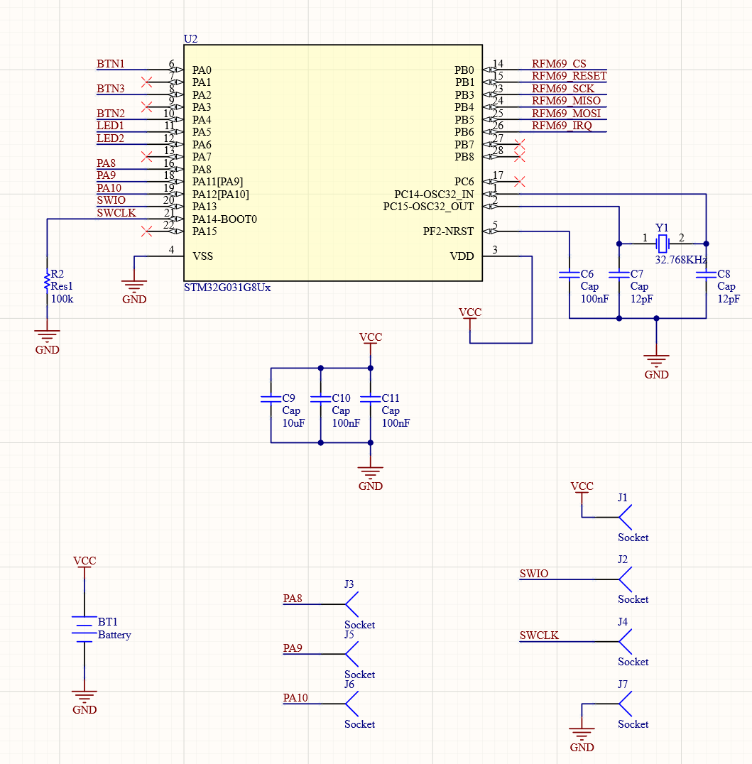
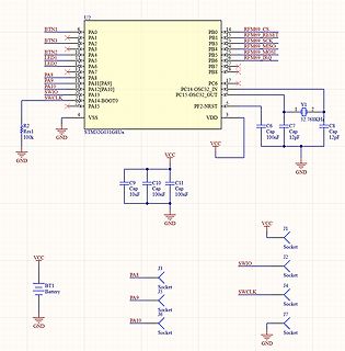
Schaltplan eines STM32G031G8Ux Mikrocontrollers
U2 STM32G031G8Ux, BTN1, BTN3, BTN2, LED1, LED2, PA8, PA9, PA10, SWIO, SWCLK, PA0 bis PA15, VSS, VDD, PF2-NRST, PC6, PC14-OSC32_IN, PC15-OSC32_OUT, RFM69 CS, RESET, SCK, MISO, MOSI, IRQ, C6, C7, C8, C9, C10
in „STM32G031G8 Grundbeschaltung / keine Verbindung über SWD“ · Mikrocontroller und Digitale Elektronik · · Schaltpläne
-
 Bild
Bild
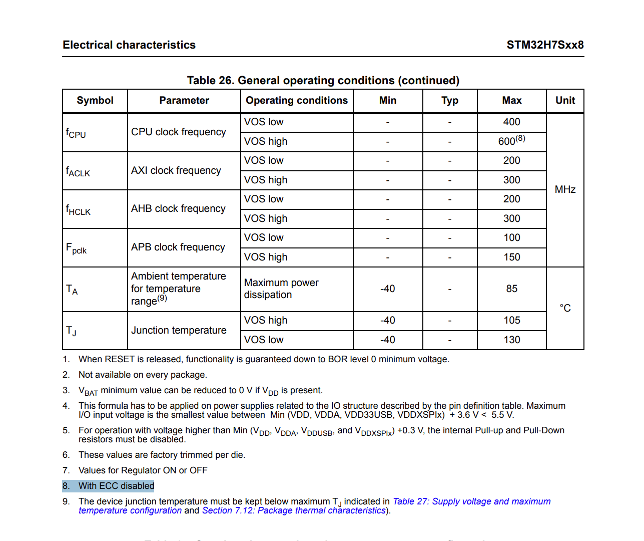
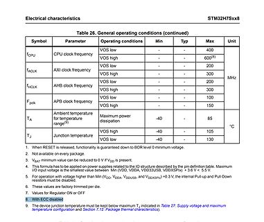
Tabelle der allgemeinen Betriebsbedingungen STM32H7Sxx8
Electrical characteristics STM32H7Sxx8 Table 26. General operating conditions (continued) Symbol Parameter Operating conditions Min Typ Max Unit fCPU CPU clock frequency VOS low - - 400 VOS high - - 600(8) fACLK AXI clock frequency
in „STM32H7Sx: Maximale Frequenz?“ · Mikrocontroller und Digitale Elektronik · · Screenshots
-
Datei
NF-Generator-407.c
/* STM32F407 www.mino-elektronik.de 2016-11-08 */ #include <stdio.h> #include <stdint.h> #include <stdlib.h> #include <stm32f4xx.h> #include <stm32f4xx_gpio.h> #include <stm32f4xx_rcc.h> // LCD-Routinen in
in „Frequenz Erzeugung mit avr“ · Mikrocontroller und Digitale Elektronik ·
-
PDF
Verfuegbare_Teile.pdf
PS - 5S 20 640 768 83 Omron 61F - GP - N2 6 144 172.8 84 Omron H3CR - A8E 1 46 55.2 85 Omron H2C - 8 4 364 436.8 86 Euchner STM1N - 222B024 - M 2 368 441.6 87 Euchner STM2N - 222B024 - M 1 184 220.8 88 Euchner NM01VZA - M 10 330 396 89 Euchner NM02VZA - M 5 180 216 90 Euchner NM11VZA - M 19 741 889.2 91 Euchner 74080 6 54 64.8 92 Hiquel TCL - 3 230V 10 610 732 93 Hiquel TCL 230V 8 488 585.6 94 Jumo 701540/811 - 02 7 763 915.6 95 Jumo 701540/811 - 31 8 1032 1238.4 96 Hiquel TCL 24V 15 915 1098 97 Hager EG103 8 512 614.4 98
in „[V] Diverses Elektromaterial. Lagerauflösung.“ · Markt ·
-
 Bild
Bild
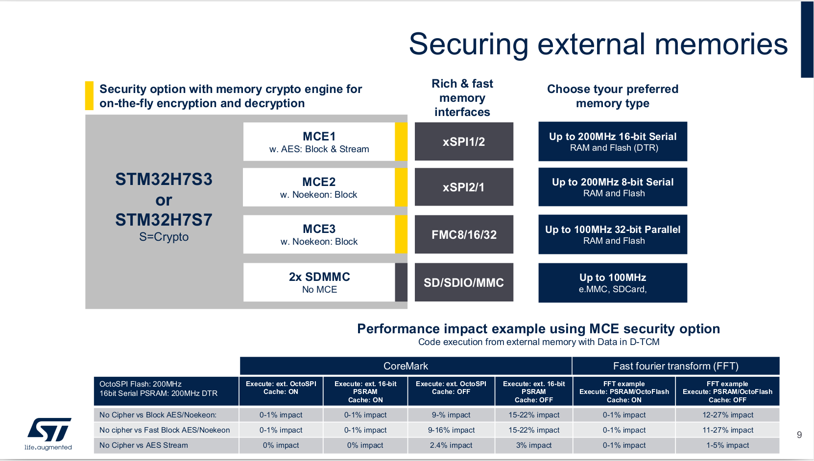
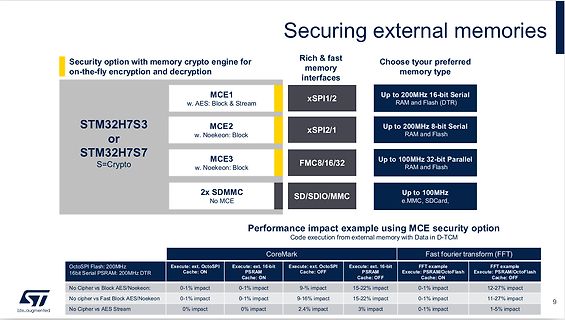
Präsentation von STM32H7S/S Speicherverschlüsselungsoptionen
external memories Security option with memory crypto engine for on-the-fly encryption and decryption STM32H7S3 or STM32H7S7 S=Crypto MCE1 w. AES: Block & Stream xSPI1/2 Up to 200MHz 16-bit Serial RAM and Flash MCE2 w. Noekeon: Block xSPI2/1 Up to 200MHz 8-bit Serial RAM and Flash MCE3 w. Noekeon: Block FMC8/16/32 Up to 100MHz 32-bit Parallel RAM and Flash 2x SDMMC No MCE SD/SDIO/MMC Up to 100MHz e.MMC, SDCard Performance impact example using MCE security option Code execution from external memory with Data
in „Neue STM32H7-Variante, Eclipse-Daten zur IoT-Adoption und neue Kameras“ · Mikrocontroller und Digitale Elektronik · · Screenshots
-
PDF
OLIMEX-stm32-p107-schematic.pdf
0 3 2 +5V_EXT 5 6 IN OUT 1 2 VI VO R73 1 2 3 GND/1DJ HN2x3 ADJ/GND CLOSE U4 10k R6 C11 R59 R60 NA(STM1001RWX6F) YDJ-1136 100R/1% C C C C R8 C 1 470R 470R R74 RST B1_0/B1_1 4 + 5 6 + 7 240R/1% + 9 0 2 VCC RESET1 HN1x3 6VAC + 100nF 330R (6.5-9)VDC C1 C2 1 4 1 4 4 2 GN3 470uF/16VDC 0 u 0 u u 2 R75 100nF C3 n / n / / F GND T 100R/1% STM32-P107 F 3 F 3 R9 C8 3 / STAT1 STAT2 0 R7 ( V V V . GNDA_E ( Rev. Initial 300R/1% u T T ( T V 1 2 3 GND_PIN . N N 390R/1% F N AGND GREEN(GYX-SD-TC0805SGCYELLOW(GYX-SD-TC0805SYC) RESET 2 C55 ) T T 3
in „Streuung der ADC-Werte beim STM32“ · Mikrocontroller und Digitale Elektronik ·
-
Datei
CANmc.cpp
= ENABLE; NVIC_Init(&NVIC_InitStructure); } int main(void) { CanTxMsg canMessage; uint8_t TransmitMailbox = 0; uint8_t CAN_Status0; CAN_Config(); NVIC_Config(); canMessage.StdId = 0x123; //Standard Identifier canMessage.ExtId = 0; //Extended Identifier canMessage.RTR = CAN_RTR_DATA; //Remote Transition Request canMessage.IDE = CAN_ID_STD; //Chosse StdId or ExtId canMessage.DLC = 8; //Length of data in bytes for(int i = 0; i < 8; i++) { canMessage.Data[i] = i+1; //Data } int j = 0; //no mailbox empty bit while(1) { //Check if at least one transmit mailbox is available j = 0; while
in „STM32F4 CAN Mailbox Problem“ · Mikrocontroller und Digitale Elektronik ·
-
 Bild
Bild
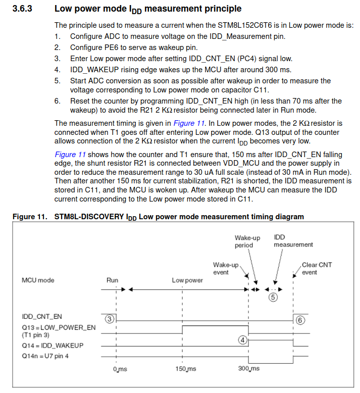
Messprinzip der IDD-Stromaufnahme im Low-Power-Modus
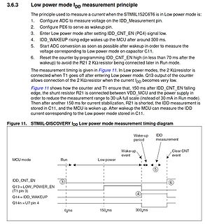
3.6.3 Low power IDD measurement principle The principle used to measure a current when the STM8L152C6T6 is in Low power mode is: 1. Configure ADC to measure voltage on the IDD_Measurement pin. 2. Configure PE6 to serve as wakeup pin. 3. Enter Low power mode after setting IDD_CNT_EN (PC4) signal
in „Strommessung im µA-mA Bereich - Automatischen Umschalten, Ansätze, Fragen“ · Analoge Elektronik und Schaltungstechnik · · Screenshots
-
 Bild
Bild
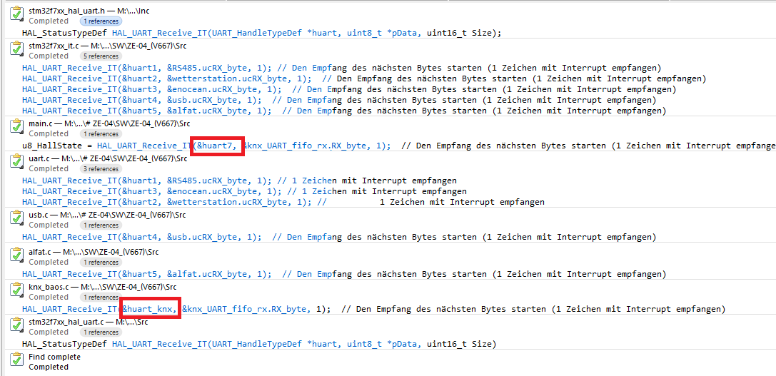
Screenshot einer IDE mit C-Quellcode
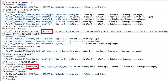
stm32fx_hal_uart.h - M...\ c Completed 1 references HAL_StatusTypeDef HAL_UART_Receive_IT(&huart, uint8_t *pData, uint16_t Size); stm32fx_it.c - M...\ c Completed 5 references HAL_UART_Receive_IT(&huart1
in „STM32F767: "HAL_UART_Receive_IT" bringt busy“ · Mikrocontroller und Digitale Elektronik · · Screenshots
-
Datei
hd44780.h
-'- (Takt) E 6 ------------ 12 PA6 | D0 7 n.c. --- D1 8 n.c. D2 9 n.c. D3 10 n.c. D4 11 ------------ 6 PA0 D5 12 ------------ 13 PA7 D6 13 ------------ 7 PA1 D7 14 ------------ 10 PA4 Hinweis: Alle Anschluesse des Controllers muessen mit einem 10K Pull-Up
in „Live-Linux: Anleitung schreiben“ · PC Hard- und Software ·
-
PDF
3.2_LCD_Module_SPEC.pdf
/ UTFT_Buttons /Utouch Library for arduino. provided 12-examples with Arduino ,3-examples with STM32 With SD Card Socket With SPI FLASH circuit Specifications Item Description Display Type 3.2 inch a-si TFT LCD Module Glass Type TFT IPS(Full-Angle) Display Resolution 480XRGBX320 Pixels Back
-
Datei
Modul2.txt
LSEinfahrtSBHSud = PB12; const int LSEinfahrtWendelSudU = PB13; const int SensorFahrstrom = PB1; uint8_t SensorFahrstromState = 0; uint8_t SensorFahrstromStateformer = 0; uint8_t LSEinfahrtSBHSudState = 0; uint8_t LSEinfahrtSBHSudStateformer = 0; uint8_t LSEinfahrtWendelSudUState = 0; uint8_t LSEinfahrtWendelSudUStateformer
in „Mehrere CAN Teilnehmer“ · Mikrocontroller und Digitale Elektronik ·
-
Datei
WC-Arduino_1.txt
arduino_build_123708\sketch\ntp.cpp.o C:\Users\Heiko\AppData\Local\Temp\arduino_build_123708\sketch\stm32flash.cpp: In function 'int stm32_bootloader(int)': stm32flash.cpp:1104:32: error: invalid conversion from 'char*' to 'const uint8_t* {aka const unsigned char*}' [-fpermissive] Serial.write (buffer
-
Datei
quellcode.txt
#include "stm32f10x.h" // STM32F10x Library Definitions #include "hardware.h" // defining hardware access #include "usb_lib.h" #include "usbutilities.h" #include "usb_istr.h" /* Prototypes*/ static void RCC_Configuration
in „Cortex M3 wird sehr heiß“ · Mikrocontroller und Digitale Elektronik ·
-
 Bild
Bild
STM32F4 Discovery Entwicklungsboard
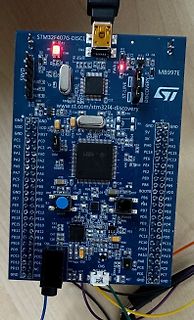
STM32F4G-DISC1, LD1, D1, R1, CN1, D2, R2, COM, R5, R6, X1, C7, R3, U2, C12, C13, R18, R15, R16, R17, C9, C14, C21, C16, R22, P1, GND, VDD, GND, P2, ST-LINK, MB997E, ST, DISCOVERY, www.st.com/stm32f4-discovery
in „STM32F407 DISCOVERY mit EVE3 50GTPC von MatrixOrbital“ · Mikrocontroller und Digitale Elektronik · · Platinenfotos
-
Datei
Stm32F030_uart.cpp
#include <stdint.h> #include "Pipe.h" #include "stm32f030x6.h" #include "stm32f0xx_hal.h" Pipe<32, uint8_t> ReceiverQueue; Pipe<32, uint8_t> SendQueue; extern UART_HandleTypeDef huart1; bool s_IsSending_bt = false; uint8_t s_EchoCnt_u8 = 0U; const uint32
in „STM32F030 ParityError nur bei aktiviertem RXNEIE?“ · Mikrocontroller und Digitale Elektronik ·
-
Datei
sim010620101014.c
/h2> */ /* Includes ------------------------------------------------------------------*/ #include "stm32f10x.h" #include "USART.h" /** @addtogroup STM32F10x_StdPeriph_Examples * @{ */ /** @addtogroup ADC_RegSimul_DualMode * @{ */ //int bla = 0; unsigned char it_active=1; int stop; ///////////////////
in „STM32 STD Libary Examples ADC RegSimul_DualMode“ · Mikrocontroller und Digitale Elektronik ·
-
Datei
startup_stm32f4xx.c
(void); void WEAK RTC_Alarm_IRQHandler(void); void WEAK OTG_FS_WKUP_IRQHandler(void); void WEAK TIM8_BRK_TIM12_IRQHandler(void); void WEAK TIM8_UP_TIM13_IRQHandler(void); void WEAK TIM8_TRG_COM_TIM14_IRQHandler(void); void WEAK TIM8_CC_IRQHandler(void); void WEAK DMA1_Stream7_IRQHandler(void); void
in „GCC STM32F4 -> Wie Variablen auf RAM bereiche verteilen“ · Mikrocontroller und Digitale Elektronik ·
-
Datei
startup_stm32f4xx.c
(void); void WEAK RTC_Alarm_IRQHandler(void); void WEAK OTG_FS_WKUP_IRQHandler(void); void WEAK TIM8_BRK_TIM12_IRQHandler(void); void WEAK TIM8_UP_TIM13_IRQHandler(void); void WEAK TIM8_TRG_COM_TIM14_IRQHandler(void); void WEAK TIM8_CC_IRQHandler(void); void WEAK DMA1_Stream7_IRQHandler(void); void
in „STM32 ohne CMSIS aber mit den includes etc. in CoIDE“ · Mikrocontroller und Digitale Elektronik ·
-
Datei
tools.c
-------- */ uint16_t changes = 0; uint32_t cells = 0; // 2 Spielfelder alt+neu struct feld_t { uint8_t last[MAX_X+1][MAX_Y+1]; uint8_t next[MAX_X+1][MAX_Y+1]; } feld; /* Die Abbildung der Matrix auf das Display */ uint8_t matrix[MAX_X+1][MAX_Y+1]; /* Datenmatrix für alle 12 Module Es werden nacheinander
in „Umgang mit globalen Datenstrukturen“ · Mikrocontroller und Digitale Elektronik ·
-
Datei
GLCD.h
define R133 0x85 #define R134 0x86 #define R135 0x87 #define R136 0x88 #define R137 0x89 #define R139 0x8B #define R140 0x8C #define R141 0x8D #define R143 0x8F #define R144 0x90 #define R145 0x91 #define R146 0x92 #define R147 0x93 #define R148 0x94 #define R149 0x95 #define R150 0x96 #define R151 0x97
in „STM32 24Bit Bmp nach 565RGB Format“ · Mikrocontroller und Digitale Elektronik ·
-
Datei
GLCD.h
define R133 0x85 #define R134 0x86 #define R135 0x87 #define R136 0x88 #define R137 0x89 #define R139 0x8B #define R140 0x8C #define R141 0x8D #define R143 0x8F #define R144 0x90 #define R145 0x91 #define R146 0x92 #define R147 0x93 #define R148 0x94 #define R149 0x95 #define R150 0x96 #define R151 0x97
in „STM32 24Bit Bmp nach 565RGB Format“ · Mikrocontroller und Digitale Elektronik ·
-
Datei
CAN2_1.txt
// -------------------------------------- Umbenenen der STM Pins // Bliotheken //------------------------------------------------------------------------------------------------------------Testweise auskommentiert #include <assert.h> #include "stm32f103.h" /
in „Arduino Blue Pill & CAN mit SN65HVD230“ · Mikrocontroller und Digitale Elektronik ·
-
Datei
CAN_Senden_4_0.txt
Übertragung zuweisen ------- Funktionstest OK */ //-------------------------------------- Umbenenen der STM Pins // Bliotheken //------------------------------------------------------------------------------------------------------------Testweise auskommentiert #include <assert.h> #include "stm32f103.h" /
in „Arduino Blue Pill & CAN mit SN65HVD230“ · Mikrocontroller und Digitale Elektronik ·
-
Datei
main.c
--------------------------------------------------------------------- #include <stdio.h> #include "stm32f10x.h" #include "stm32f10x_conf.h" #include "stm32f10x_tim.h" /* Private typedef -----------------------------------------------------------*/ /* Private define -----------------------------------
in „STM32 - Eclipse, ARM GCC - Funktionsaufruf geht nicht :-(“ · Mikrocontroller und Digitale Elektronik ·
-
Datei
eventctrl_uc.ino
---------------------- Objektinstanz von shiftreg595 erstellen Usage: shiftreg595::shiftreg595(uint8_t clk, uint8_t dat, uint8_t stb) ---------------------------------------------------------------------- */ // shiftreg595 sr(2, 3, 15); // stm32 r3-Board (PB7, PB6, PB13) // shiftreg595 sr(5, 3, A2);
in „Schulnotenbewertung eines Arduino-Programms“ · Mikrocontroller und Digitale Elektronik ·
-
PDF
STM32H7-Base.pdf
1 2 3 4 +3V3 COR Y2 2 OSC8M R4 OSC8MR8MR 3 4 PI10 CC33 PI401 PIR402 P I Y2 0 3 OUT VDD P I Y2 0 4 10nF 50V X7R 22R P I Y2 0 1 P I Y2 0 2 PI2 COUB +3V3 EN GND A U1A U1B A 40 142 66 131 KC2520Z8.0000C1KX00 PI U10 40 PA0 PD0 PIU
in „STM32H7 und JTAG: Irgendwelche Fallstricke“ · Mikrocontroller und Digitale Elektronik ·
-
Datei
CRC.cpp
0x7e, 0x40, 0x02, 0x3c, 0x86, 0xb8, 0xfa, 0xc4, 0xa4, 0x9a, 0xd8, 0xe6, 0x5c, 0x62, 0x20, 0x1e, 0x31, 0x0f, 0x4d, 0x73, 0xc9, 0xf7, 0xb5, 0x8b, 0x75, 0x4b, 0x09, 0x37, 0x8d, 0xb3, 0xf1, 0xcf, 0xe0, 0xde, 0x9c, 0xa2, 0x18, 0x26, 0x64,
in „Problem mit GCC-Optimierung“ · Mikrocontroller und Digitale Elektronik ·
-
Datei
mmc_stm32f1.c
// while (SPIx_SR & _BV(7)) ; // d = SPIx_DR; // SPIx_DR = 0xFFFF; // buff[1] = d; buff[0] = d >> 8; // buff += 2; // } while (btr -= 2); // while (SPIx_SR & _BV(7)) ; // d = SPIx_DR; // buff[1] = d; buff[0] = d >> 8; // // SPIx_CR1 &= ~(_BV(6) | _BV(11)); /* Set SPI to 8-bit mode */ // SPIx_CR1 |=
in „STM32Fxxx: Frage zur Initialisierung mit der StdPeriphLib“ · Mikrocontroller und Digitale Elektronik ·
-
Datei
diskio.c
/* Argument[31..24] */ xchg_spi((BYTE)(arg >> 16)); /* Argument[23..16] */ xchg_spi((BYTE)(arg >> 8)); /* Argument[15..8] */ xchg_spi((BYTE)arg); /* Argument[7..0] */ n = 0x01; /* Dummy CRC + Stop */ if (cmd == CMD0) n = 0x95; /* Valid CRC for CMD0(0) */ if (cmd == CMD8) n = 0x87; /* Valid CRC for
in „STM32 <-> AVR“ · Mikrocontroller und Digitale Elektronik ·
-
Datei
gps.h
define GPS_H_INCLUDED /* -------------------- System Include Files / Librarys ------------ */ #include "stm32f10x_conf.h" #include "system_stm32f10x.h" /* -------------------- Standard Include Files --------------------- */ #include <stdbool.h> #include <stdint.h> #include <stdlib.h> #include <string.h> #
in „uC Programmiertechniken - Gibt es da Bücher?“ · Mikrocontroller und Digitale Elektronik ·
-
Datei
SK6812.cpp
++ = *tPtr++; *bptr++ = *tPtr++; } void SK6812::setPixelColor(uint16_t n, uint32_t c) { uint8_t r,g,b; if(brightness) { r = ((int)((uint8_t)(c >> 16)) * (int)brightness) >> 8; g = ((int)((uint8_t)(c >> 8)) * (int)brightness) >> 8; b = ((int)((uint8_t)c) * (int)brightness) >> 8; } else { r = (uint8_t)(c >> 16), g = (uint8_t)(c >> 8), b = (uint8_t)c; } uint8_t *bptr = pixels + (n<<5) + n +1; uint8_t *tPtr = (uint8_t *)encoderLookup + g*11;// need to index 3 x g into the lookup *bptr++ = *tPtr++;
in „STM32 Bluepill -> SK6812 (auf Basis von WS2812B Lib)“ · Projekte & Code ·
-
PDF
Bulb_Ohm.pdf
DC-Waveform Generator for Higher Current and Lower Frequencies In this project we use a STM32F103C8 – mounted on a Black Pill – to control via I2C a 12-Bit Digital-to-Analog Converter (DAC) to generate signals like e.g. Sinus-, Triangle-, Rectangle-signals, in a voltage range of e.g. U0=0V
in „I2C STM32F103“ · Mikrocontroller und Digitale Elektronik ·
-
Datei
WS2812Ctrl.cpp
---------- Resources ----------------------------------------------------------------------- * µC: STM32F103C8 - GPIO: A0 - Timer: TIM2 - DMA: DMA1 Channel 2 - IRQ: DMA1_Channel2_IRQHandler ----------------------------------------------------------------------- Revision History ----------------------
-
Datei
ws2812_stm32f4.h
#ifndef WS2812_STM32F4_H #define WS2812_STM32F4_H // helper macro for concatenation #define CAT_(a,b) a ## b #define CAT(a,b) CAT_(a,b) // ----------------------------- definitions ----------------------------- #define WS2812_NR_LEDS 48 // warning: change source file if using tim1/8/9/10/11 // (different APB => change function calls/peripheral names/clock generation) #define WS2812_TIMER_NR 3 #define WS2812_TIM_CHAN_NR 3 #define WS2812_OUT_PORT B #define WS2812_OUT_PIN 0 #define
in „[STM32] Binäruhr bzw 12x4 RGB LED Display mit WS2812“ · Projekte & Code ·
-
Datei
main.c
/* Includes ------------------------------------------------------------------*/ #include "stm32f10x.h" #include "main.h" /** @addtogroup STM32F10x_StdPeriph_Examples * @{ */ /** @addtogroup GPIO_IOToggle * @{ */ /* Private typedef -----------------------------------------------------------*/
in „STM32 SPI2 als Master sendet nichts“ · Mikrocontroller und Digitale Elektronik ·
-
Datei
spi_oled.c
#include "STM32F4xx.h" #include "_mcpr_stm32f407.h" #include "spi_oled.h" #include "tools.h" #include "timer.h" void spiInit(void) { //CONFIGURE I/Os FOR SPI2 //SCLK = PB13 setOutputPort(B, 13, ALTERNATIVE, PUSHPULL
in „0,96 Oled mit STM32F407“ · Mikrocontroller und Digitale Elektronik ·