-
 Bild
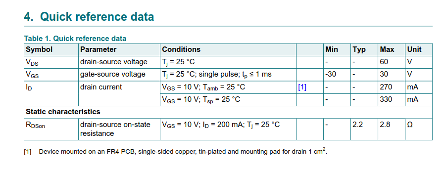
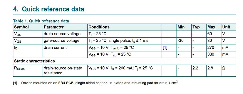
Tabelle mit technischen Daten eines MOSFETs
4. Quick reference data Table 1. Quick reference data Symbol Parameter Conditions Min Typ Max Unit VDS drain-source voltage Tj = 25 °C - - 60 V VGS gate-source voltage Tj = 25 °C; single pulse; tp ≤ 1 ms -30 - 30 V ID drain current VGS = 10 V; Tamb = 25 °C [1] - - 270 mA VGS = 10 V; Tsp = 25 °C - - 330 mA Static characteristics RDSon drain-source on-state resistance VGS = 10 V; ID = 200 mA; Tj = 25 °C - 2.2 2.8 Ω [1] Device mounted on an FR4 PCB, single-sided copper, tin-plated and mounting pad for drain 1 cm².
in „Neue Bauteile: vom Radar bis zum Widerstand“ · Mikrocontroller und Digitale Elektronik · · Screenshots
-
 Bild
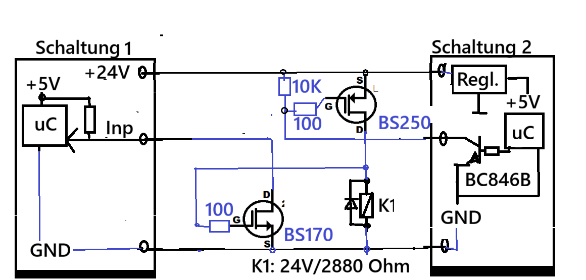
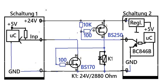
Schaltplan mit zwei Schaltungen und MOSFETs
Schaltung 1 +24V +5V uC Inp 10K 100 G S D BS250 100 G S D BS170 K1 GND Schaltung 2 Regl. +5V uC BC846B GND K1: 24V/2880 Ohm
in „Frage zu einer kleinen Transistorschaltung“ · Analoge Elektronik und Schaltungstechnik · · Schaltpläne
-
PDF
igrid_ss_3kw_plus.pdf
parameters of main SPS section The most likely problems occur on the SPS section including broken MOSFET, broken Diode, damaged sense resistor, damaged relative driver resistor with broken MOSFET. Reference Checked components Instrument function Failed Condition Value (S, D) Diode Voltage Droop 0.5V
in „PV Wechselrichter startet nicht mehr und verursacht Kurzschluss bzw. hohen Strom“ · Analoge Elektronik und Schaltungstechnik ·
-
Datei
FSM_tb.vhd
OUT std_logic; ADC_CS : OUT std_logic; ADC_INT_EOC : IN std_logic; ASI_ASIC_OUT : OUT std_logic; MOSFET : INOUT std_logic; CLK : IN std_logic; reset : IN std_logic ); END COMPONENT; --Inputs signal ASI_ASIC_IN_DUTY : std_logic_vector(1 downto 0) := "01"; signal ADC_INT_EOC : std_logic := '1'; signal
-
PDF
01_Spice_Thermal-Modelling.pdf
of the implementation of a dynamic temperature-dependent model in SPICE and SABER using a power MOSFET model as an example. Various possibilities for determining the thermal parameters are demonstrated. The possi- bilities and limitations of the new models are presented with application-based examples
in „MOSFET mit Temperaturabhängigkeit in LTSpice“ · Analoge Elektronik und Schaltungstechnik ·
-
PDF
catalog.pdf
/-20V; Gfs MPN: BS170F [ID]: 000192 [Price]: 0.4 USD [QTY]: 5 [Category]: MOSFETs [Desc]: Trans MOSFET N-CH 60V 0.00015A Automotive 3-Pin SOT-23 MPN: FDS6672A [ID]: 000193 [Price]: 1.52 USD [QTY]: 60 [Category]: MOSFETs [Desc]: Mosfet N-ch 30V 12.5A 8SOIC MPN: IRF540A [ID]: 000195 [Price]: 0.52 USD [QTY]: 10 [Category]: MOSFETs [Desc]: Trans MOSFET N-CH 100V 28A 3-Pin(3+Tab) TO-220AB Rail MPN: DMP2170U-7 [ID]: 000196 [Price]: 0.12 USD [QTY]: 4 [Category]: MOSFETs [Desc]: Transistor Mosfet P-ch 20V 3.1A 3-PIN SOT-23 T/r MPN
-
PDF
catalog-3.pdf
+/-20V; Gfs MPN: BS170F [ID]: 000192 [Price]: 0.5512 USD [QTY]: 5 [Category]: MOSFETs [Desc]: Trans MOSFET N-CH 60V 0.00015A Automotive 3-Pin SOT-23 MPN: FDS6672A [ID]: 000193 [Price]: 2.0946 USD [QTY]: 60 [Category]: MOSFETs [Desc]: Mosfet N-ch 30V 12.5A 8SOIC MPN: IRF540A [ID]: 000195 [Price]: 0.7166 USD [QTY]: 10 [Category]: MOSFETs [Desc]: Trans MOSFET N-CH 100V 28A 3-Pin(3+Tab) TO-220AB Rail MPN: DMP2170U-7 [ID]: 000196 [Price]: 0.1654 USD [QTY]: 4 [Category]: MOSFETs [Desc]: Transistor Mosfet P-ch 20V 3.1A 3-PIN SOT-23 T/r
-
PDF
Master-thesis_Wenzel-Maier_final-version.pdf
the control signals of pp3t-A and pp3t-B must be disabled. In this case, the build in diode of the MOSFETs Q3 and Q4 take over the recti▯cation function. Normally, the MOSFETs Q1/Q2 on the primary side and the MOSFETs Q3/Q4 on the secondary side works synchronous and no phase delay is required. Due to
in „Platinfuchs IIa: Isolierter, bidirektionaler 45W DC/DC Wandler zum Laden/Entladen eines Liion-Akkus“ · Projekte & Code ·
-
Datei
main_tb.vhd
OUT std_logic; ADC_CS : OUT std_logic; ADC_INT_EOC : IN std_logic; ASI_ASIC_OUT : OUT std_logic; MOSFET : INOUT std_logic; CLK : IN std_logic; reset : IN std_logic ); END COMPONENT; --Inputs signal ASI_ASIC_IN_DUTY : std_logic_vector(1 downto 0) := (others => '0'); signal ADC_INT_EOC : std_logic := '
-
Datei
FSM_tb.vhd
OUT std_logic; ADC_CS : OUT std_logic; ADC_INT_EOC : IN std_logic; ASI_ASIC_OUT : OUT std_logic; MOSFET : INOUT std_logic; CLK : IN std_logic; reset : IN std_logic ); END COMPONENT; --Inputs signal ASI_ASIC_IN_DUTY : std_logic_vector(1 downto 0) := "01"; signal ADC_INT_EOC : std_logic := '1'; signal
-
PDF
lm3421.pdf
is latched. 11 - LRDY LED Ready Flag Connect to pull-up resistor from VIN and N-channel MosFET open drain output pulls down when the LED current is not in regulation. 12 - DPOL Dim Polarity Connect to AGND if dimming with a series P-channel MosFET or leave open when dimming with series N-channel
in „Spule Dimensonierung Schaltnetzteil“ · Analoge Elektronik und Schaltungstechnik ·
-
PDF
mirkonet_tmp.pdf
NO 0,097 0,116 1,164 Farnell MLP-322 N/A fttyp.:110MhZ N/A N/A N/A N/A N/A 12 N/A 1,5 4116021 6 MOSFET IRF6620TR1 IR MOSFET, N, DIRECTFET YES YES 2,550 3,060 18,360 Farnell DIRECTFET-M N/A 150A DircetFET N-MOSFET, RDSon 2,7mOhm N/A -40/+150 N/A 150 N/A 20 N/A 89 9266593 6 MOSFET IRC840PBF VISHAY MOSFET
in „Komplettverkauf Bauteile, was wert? - Tabelle“ · Markt ·
-
PDF
MT3608.pdf
High Efficiency 1.2MHz 2A Step Up Converter GENERAL DESCRIPTION FEATURES • Integrated 80mΩ Power MOSFET The MT3608 is a constant frequency, 6-pin SOT23 • 2V to 24V Input Voltage current mode step-up converter intended for small, • 1.2MHz Fixed Switching Frequency low power applications. The MT3608 switches
in „Step up Converter 2,9V -> 12V, ca. 500mA“ · Analoge Elektronik und Schaltungstechnik ·
-
PDF
MT3608.pdf
High Efficiency 1.2MHz 2A Step Up Converter GENERAL DESCRIPTION FEATURES • Integrated 80mΩ Power MOSFET The MT3608 is a constant frequency, 6-pin SOT23 • 2V to 24V Input Voltage current mode step-up converter intended for small, • 1.2MHz Fixed Switching Frequency low power applications. The MT3608 switches
in „MT3608 - 2 x defekt?“ · Analoge Elektronik und Schaltungstechnik ·
-
PDF
SX1308.pdf
Efficiency 1.2MHz 2A Step Up Converter 85T GENERAL DESCRIPTION FEATURES • Integrated 80mΩ Power MOSFET The SX1308 is a constant frequency, 6-pin SOT23 • 2V to 24V Input Voltage current mode step-up converter intended for small, • 1.2MHz Fixed Switching Frequency low power applications. The SX1308 switches
in „6-9V auf 12V booster“ · Analoge Elektronik und Schaltungstechnik ·
-
PDF
MT3608.pdf
High Efficiency 1.2MHz 2A Step Up Converter GENERAL DESCRIPTION FEATURES • Integrated 80mΩ Power MOSFET The MT3608 is a constant frequency, 6-pin SOT23 • 2V to 24V Input Voltage current mode step-up converter intended for small, • 1.2MHz Fixed Switching Frequency low power applications. The MT3608 switches
in „Vergleichstyp WD3133“ · Analoge Elektronik und Schaltungstechnik ·
-
PDF
MT3608.pdf
High Efficiency 1.2MHz 2A Step Up Converter GENERAL DESCRIPTION FEATURES • Integrated 80mΩ Power MOSFET The MT3608 is a constant frequency, 6-pin SOT23 • 2V to 24V Input Voltage current mode step-up converter intended for small, • 1.2MHz Fixed Switching Frequency low power applications. The MT3608 switches
in „Kleiner stepup-wandler 3V zu 12V“ · Analoge Elektronik und Schaltungstechnik ·
-
PDF
SX1308.pdf
Efficiency 1.2MHz 2A Step Up Converter 85T GENERAL DESCRIPTION FEATURES • Integrated 80mΩ Power MOSFET The SX1308 is a constant frequency, 6-pin SOT23 • 2V to 24V Input Voltage current mode step-up converter intended for small, • 1.2MHz Fixed Switching Frequency low power applications. The SX1308 switches
in „Kleiner stepup-wandler 3V zu 12V“ · Analoge Elektronik und Schaltungstechnik ·
-
PDF
SDB628.pdf
High Efficiency 1.2MHz 2A Step Up Converter FEATURES GENERAL DESCRIPTION • Integrated 80mΩ Power MOSFET The SDB628 is a constant frequency, 6-pin SOT23 • 2V to 24V Input Voltage current mode step-up converter intended for small, • 1.2MHz Fixed Switching Frequency low power applications. The SDB628 switches
in „Schaltregler, Feedback und Op Amp“ · Analoge Elektronik und Schaltungstechnik ·
-
PDF
MT3608.pdf
High Efficiency 1.2MHz 2A Step Up Converter GENERAL DESCRIPTION FEATURES • Integrated 80mΩ Power MOSFET The MT3608 is a constant frequency, 6-pin SOT23 • 2V to 24V Input Voltage current mode step-up converter intended for small, • 1.2MHz Fixed Switching Frequency low power applications. The MT3608 switches
in „Unbekannter SMD-Marking-Code CP5R und 4061 1616“ · Analoge Elektronik und Schaltungstechnik ·
-
PDF
SDB628.PDF
High Efficiency 1.2MHz 2A Step Up Converter FEATURES GENERAL DESCRIPTION • Integrated 80mΩ Power MOSFET The SDB628 is a constant frequency, 6-pin SOT23 • 2V to 24V Input Voltage current mode step-up converter intended for small, • 1.2MHz Fixed Switching Frequency low power applications. The SDB628 switches
in „ESP32-C6 an 18650 Akku betreiben“ · Mikrocontroller und Digitale Elektronik ·
-
PDF
BL8028_V1.13_en.pdf
amplifier senses the rectifier improves efficiency and eliminates the current through the high-side MOSFET during on time and produces a proportional current signal, typical Schottky free-wheeling diode. Using theon whichisusedtosumwiththeslopecompensation resistance of the internal high-side MOSFET to
in „Küchenwaage ohne Funktion“ · Mikrocontroller und Digitale Elektronik ·
-
PDF
AN3241.pdf
over-voltage protection. The circuit in Figure 4 adds some of these features by means of external MOSFETs driven by voltage detectors in the charger IC. Page 3 of 7 Figure 4. SOT-23 power MOSFETs add useful features such as over-voltage protection and battery disconnect when external power is applied.
in „Self-Powered / USB-Powered umschalten“ · Mikrocontroller und Digitale Elektronik ·
-
PDF
Platinfuch_IIa_BOM_20210217.pdf
0.246 45 1 L8 Inductor TDK 0805 MLZ2012M100WT000 Digi-Key 445-6396-2-ND 0.037 0.037 46 2 Q1, Q2 MOSFET Nexperia LFPAK56 PSMN3R3-40YS,115 Digi-Key 1727-4633-2-ND 0.298 0.596 47 4 Q3, Q4, Q5, Q6 MOSFET Nexperia LFPAK56 PSMN2R4-30YLDX Digi-Key 1727-1792-2-ND 0.223 0.892 48 2 Q7, Q8 MOSFET Nexperia LFPAK56 PSMN0R9-25YLC,115 Digi-Key 1727-5292-2-ND 0.365 0.730 49 2 Q9, Q10 MOSFET Infineon SOT23-3 IRLML0040TRPBF Digi-Key IRLML0040TRPBFTR-ND 0.102 0.204 50 6 Q11, Q12, Q13, Q14, Q15, Q16 MOSFET Infineon SOT23-3 2N7002NXAKR Digi-Key 1727-8643-2-ND 0.011 0.068 51 1 R1 Resistor 0805
in „Platinfuchs IIa: Isolierter, bidirektionaler 45W DC/DC Wandler zum Laden/Entladen eines Liion-Akkus“ · Projekte & Code ·
-
PDF
semicon.pdf
918 x BAS221 SMD 1000 HVE300A7TRU varicap SMD 3000 Félvezetık / tranzisztor fet FET STM STP36N06 Mosfet TO 220 700 FET IR IRLIZ24N Mosfet TO 220 3000 FET IR IRFIBC30G Mosfet TO 220 800 FET IR IRFU014 Mosfet TO251AA 1500 IGBT IR IRG4RC10SDTR IGBT TO252AA 1000 FET IR IRFBC40 Mosfet TO 220 1000 FET IR IRF1010NS Mosfet D2Pak 3000 FET Vishay SI4834BDY T1 dual Mosfet 30V / 7,5A / 0,022R SO8 500 x Motorola MMDF2P02 dual Mosfet SO8 689 x BC108 BBS TO92 535 x MMBT4401 LT1 SOT23 1100 x MMBT5089 LT1 SOT23 400 x MMBT2222
in „4" TFT für 7,97€“ · Markt ·
-
PDF
AL5801.pdf
Dimming (a) (b) Figure 16 Application Circuits for LED Driver with PWM Dimming Functionality (a) MOSFET driving and (b) Transistor driving PWM dimming can be achieved by driving the BIAS pin (1). An external open-collector NPN transistor or open-drain N-channel MOSFET can be used to drive the BIAS pin
in „Suche Konstantstromquelle effizient, klein und günstig.“ · Analoge Elektronik und Schaltungstechnik ·
-
PDF
info-uiir2156.pdf
Equations 1 and 2). Once disconnected from COM and an internal 4µA CT discharges below 1/3 VCC, MOSFET S3 is currentsource(Figure3) turned off, disconnecting RDT from COM, and MOSFET S1 is turned on, connecting RT and VBUS+) RPHagaintoVCC.Thefrequencyremainsatthe preheat frequency until the voltage
in „Leuchtstoffröhren Vorschaltgerät 24V Reparatur-Tipp gesucht“ · Fahrzeugelektronik ·
-
PDF
BM3451-BYDMicroelectronics.pdf
reference 10 9 VM Voltage detection terminal 1 for detecting load or charger 11 10 CO Charge power mosfet control terminal, Open-Drain output 12 11 DO Discharge power mosfet control terminal, CMOS output Datasheet WI-D06-J-0036 Rev.A/1 4 /28 BYD Microelectronics Co., Ltd. BM3451 Series 13 - BALDN Balance
in „ST µC Identifikation“ · Mikrocontroller und Digitale Elektronik ·
-
PDF
BM3451_BMS.pdf
reference 10 9 VM Voltage detection terminal 1 for detecting load or charger 11 10 CO Charge power mosfet control terminal, Open-Drain output 12 11 DO Discharge power mosfet control terminal, CMOS output Datasheet WI-D06-J-0036 Rev.A/1 4 /28 BYD Microelectronics Co., Ltd. BM3451 Series 13 - BALDN Balance
in „Balancer IC Li-Ionen Akku“ · Analoge Elektronik und Schaltungstechnik ·
-
PDF
2025-08-25_Karlsolar__de_.pdf
als sehr konservativ heraus – die Verringerung des Shuntwiderstands, so wie die Bestückung aller MOSFETs, wird problemlos eine höhere Leistungsfähigkeit ermöglichen. Kühlung (passiver Kühlkörper oder aktive Kühlung) sollte erneut eine deutliche Leistungssteigerung erlauben. ▪ Das BMFE ist derart konzipiert
in „Open Source-BMS für kleine Inselanlagen auf 48V-Basis (Karlsolar)“ · Projekte & Code ·
-
PDF
Transistoren_cht.pdf
www.datasheetarchive.com This datasheet has been downloaded from http://www.datasheetarchive.com. Power MOSFETs Cross Reference Alphanumerically Part VDSS RDS(ON) D PD Package Toshiba Note Vender Number (V) (ohm) (A) (W) Replacement 2N7000 60 5 0.2 0.4 TO-92 Fairchild 2N7002 60 7.5 0.115 0.2 SOT-23 Fairchild
in „Frage Mosfet“ · Analoge Elektronik und Schaltungstechnik ·
-
PDF
Power_MOSET_Cross_reference.pdf
Power MOSFETs Cross Reference Alphanumerically Part VDSS RDS(ON) D PD Package Toshiba Note Vender Number (V) (ohm) (A) (W) Replacement 2N7000 60 5 0.2 0.4 TO-92 Fairchild 2N7002 60 7.5 0.115 0.2 SOT-23 Fairchild
in „Schaltregler Fragen“ · Analoge Elektronik und Schaltungstechnik ·
-
PDF
lm5165.pdf
60 70 0 10 20 30 40 50 60 70 Input Voltage (V) Input Voltage (V) D001 D002 Figure 6-7. High-Side MOSFET On-State Figure 6-8. Low-Side MOSFET On-State Resistance Resistance vs Input Voltage vs Input Voltage 1.24 1.25 1.22 ) 1.245 ( s 1.24 ) 1.2 l ( h 1.235 l e o 1.18 h 1.23 s n r 1.16 i 1.225 T l N g
in „Stromverbrauch Schaltregler“ · Analoge Elektronik und Schaltungstechnik ·
-
PDF
TPS5430.pdf
ms THERMAL SHUTDOWN Thermal shutdown trip point 135 162 °C Thermal shutdown hysteresis 14 OUTPUT MOSFET VIN = 5.5 V 150 DS(on) High-side power MOSFET switch mΩ 110 230 Copyright © 2006–2017, Texas Instruments Incorporated Submit Documentation Feedback 7 Product Folder Links: TPS5430 TPS5431 TPS5430,TPS5431
in „DigiPot AD5290 und Schaltregler TPS5430 laufen nicht zusammen“ · Analoge Elektronik und Schaltungstechnik ·
-
PDF
EG8010_datasheet.pdf
O Over voltage: Below voltage: Over temperature: PWM type select “0”: positive polarity PWM type,MOSFET on when SPWMOUT is high “1” positive polarity PWM type,MOSFET on when SPWMOUT is low 9 PWMTYP I Best configuring pin according to driver device and referring to the typical application schematic below
in „Inverter DC/AC mit EGS002 China DEV-Board“ · Analoge Elektronik und Schaltungstechnik ·
-
PDF
DE2008071001.pdf
tenPegelbekommen.D3undD4schützen halben Dual-Opamps steuern je einen seinnachgeschalteterMOSFETwirddurch- die Gates der Power-MOSFETs. Power-MOSFET. gesteuert.MitP1beziehungsweiseP2lässt Der aktive Gleichrichter eignet sich in BeimEinschaltensinddie Lade-Elkos noch sich individuell einstellen, bei welcher Dif- der angegebenen Dimensionierung für leer, so dass die in jedem MOSFET vorhan- ferenzspannung zwischen Ausgang und Ausgangsströme bis etwa 5 A. Die Trafo - denen parasitären Dioden endlich einmal Eingang das Gate des zugehörigen FETs spannung ist auf 15 V und damit die
in „Howto Aktiver Gleichrichter“ · Analoge Elektronik und Schaltungstechnik ·
-
PDF
LTC4054-4.2.pdf
Programmable Charge Current Up to 800mA The LTC 4054 is a complete constant-current/constant- No MOSFET, Sense Resistor or Blocking voltagelinearchargerforsinglecelllithium-ionbatteries. Diode Required Its ThinSOT package and low external component count TM Complete Linear Charger in ThinSOT Package
in „akku mit solar aufladen, kommt das IC: LT1734L dafür in Frage?“ · Analoge Elektronik und Schaltungstechnik ·
-
PDF
NCP51530-D-1324764-1.pdf
source/sink capability which can effectively charge and the drive voltage level the external power MOSFET turns on discharge a 1 nF load in 15 ns. the external MOSFET to discharge to GND/HB level. The outputs of NCP51530 can be turned on at the same When a logic low signal is received from the input stage
in „Hilfe bei Halbbrückenschaltung benötigt“ · Analoge Elektronik und Schaltungstechnik ·
-
PDF
tps62933-1.pdf
= –40°C to 150°C 784 800 816 mV J IFB Input leakage current V FB= 0.8 V 0.1 μA INTEGRATED POWER MOSFETS R High-side MOSFET on-resistance T = 25°C, V – SW = 5 V 76 mΩ DSON_HS J BST R DSON_LS Low-side MOSFET on-resistance TJ= 25°C 32 mΩ CURRENT LIMIT I High-side MOSFET current limit 4.2 5 5.8 A HS_LIMIT
in „TI Buck TPS62933.“ · Analoge Elektronik und Schaltungstechnik ·
-
PDF
PWM_20schemes_20for_20BLDC.pdf
” and used in many MOSFET-based power converters [2]. By using MOSFETs with low conduction resistance, conduction losses can be reduced to less than that of the diode alone. Fig. 2.4A shows current ripple similar to scheme
in „Diskrete H-Brücke“ · Analoge Elektronik und Schaltungstechnik ·
-
PDF
01149c.pdf
that are designed to Circuit. simply connect the system load to the Li- Ion battery. Selecting The MOSFET 2. The total system current is limited by the charge The nature of the MOSFET makes it the best candidate current because the charger will deliver total for current direction control. A P-Channel MOSFET
in „Frage zu AN1149 - Load Sharing Microchip“ · Analoge Elektronik und Schaltungstechnik ·
-
PDF
tps2552.pdf
device incorporates an internal charge pump and gate drive circuitry necessary to drive the N-channel MOSFET. The charge pump supplies power to the driver circuit and provides the necessary voltage to pull the gate of the MOSFET above the source. The charge pump operates from input voltages as low as 2.5
in „Problem mit FSUSB30 als USB-Schalter“ · Mikrocontroller und Digitale Elektronik ·
-
PDF
iW3689_CN_to_EN.pdf
avoid vias; do not put the transformer. Dialog Semiconductor Confidential Internal Only © 2015 18 MOSFET Related MOSFET Package: Recommended TO-252 SMD package, to avoid customer ON / OFF When tested, because MOSFET Overheat and lead to product failure. Dialog Semiconductor Confidential Internal Only
in „Nicht dimmbare LED Spots nachrüsten“ · Mikrocontroller und Digitale Elektronik ·
-
PDF
Transistortester097k.pdf
. . . . . . . . . . . . . . . .15 . . . . 4.1.1 Messung eines PNP-Transistors oder eines P-Kanal MOSFETs . . . . . . . . .15 4.1.2 Messung eines NPN Transistors oder eines N-Kanal-MOSFET . . . . . . . . . 17 4.1.3 Messung von Dioden . . . . . . . . . . . . . . . . . . . . . . . . . . . .19 . . . 4.1.4
-
PDF
MAX1647.PDF
— SDA Serial Data 15 — DACV Voltage DAC Output 16 12 PGND Power Ground 17 13 DLO Low-Side Power MOSFET Driver Output 18 14 DHI High-Side Power MOSFET Driver Output 19 15 LX Power Connection for the High-Side Power MOSFET Driver 20 16 BST Power Connection for the High-Side Power MOSFET Driver _______
in „Win98 Diagnose Notebook Akku immer 50%“ · PC Hard- und Software ·
-
PDF
QEagleBeta.pdf
«pin (100,200) (0,0) 1 0 0 0x0 -1 "E"» ← Spiceorder 3 » » Seite 25 Entwicklernotizen 2.2.4 Einen MOSFET anlegen - Create a MOSFET Grundsätzlich verläuft das erstellen eines Mosfet wie bei einem bipolaren Transistor. Zuerst das Symbol zeichnen, wobei die Reihenfolge 1=Drain, 2=Gate und 3=Source, ist.
in „QSPICE von Mike Engelhardt“ · Analoge Elektronik und Schaltungstechnik ·
-
PDF
MAX1647_1_.PDF
— SDA Serial Data 15 — DACV Voltage DAC Output 16 12 PGND Power Ground 17 13 DLO Low-Side Power MOSFET Driver Output 18 14 DHI High-Side Power MOSFET Driver Output 19 15 LX Power Connection for the High-Side Power MOSFET Driver 20 16 BST Power Connection for the High-Side Power MOSFET Driver _______
-
PDF
Wasserwarner.pdf
R2 schützt das lativ niedrige Kapazität. Während der warner sendet ein intervall-gesteu- Gate des MOSFET gegen Überspan- Pausen, in denen der Beeper inaktiv ertes akustisches Signal aus, sobald nungen, wie sie zum Beispiel beim Be- ist, geht der größte Teil der Stromauf- sein Sensor mit Wasser in Berührung
in „Diskrete Schaltung: Tongeber etwa 1 Sekunden an, 5 Sekunden aus“ · Analoge Elektronik und Schaltungstechnik ·