-
Datei
3-Port_Sinus-Demo.c
// Software-PWM by PoWl - 23.10.08 // webmaster@the-powl.de // ATmega8 @ 8Mhz #include <avr/io.h> #include <avr/interrupt.h> #include <util/delay.h> #include <stdbool.h> // Sinustabelle für Demo const uint8_t sinetable[] = { 128, 131, 134, 137, 140, 143, 146, 149, 152
in „8-Bit Software PWM für mehr als 8 Kanäle“ · Projekte & Code ·
-
Datei
3-Port_Sinus-Demo.c
// Software-PWM by PoWl - 25.10.08 // webmaster@the-powl.de // ATmega8 @ 8Mhz #include <avr/io.h> #include <avr/interrupt.h> #include <util/delay.h> #include <stdbool.h> // Sinustabelle für Demo const uint8_t sinetable[] = { 128, 131, 134, 137, 140, 143, 146, 149, 152
in „Software-PWM stockt bei unpassender Updatefrequenz“ · Mikrocontroller und Digitale Elektronik ·
-
Datei
dude5.4arduino_avr911.txt
Port : /dev/cu.SLAB_USBtoUART Using Programmer : avr911 Overriding Baud Rate : 19200 AVR Part : ATMEGA8 Chip Erase delay : 10000 us PAGEL : PD7 BS2 : PC2 RESET disposition : dedicated RETRY pulse : SCK serial program mode : yes parallel program mode : yes Timeout : 200 StabDelay : 100 CmdexeDelay :
in „avrdude - Probleme unter Mac OS X 10.7 (Lion)“ · Mikrocontroller und Digitale Elektronik ·
-
Datei
kb.c
/* this keyboard interface is based on avr appnote 313 changes are made for using avr-gcc and atmega8 processors beck@informatik.htw-dresden.de */ #include <device.h> /* ************************************************************************************ */ // Quelle: keyboard.c von // hevans@nerdkits.com
in „PS/2 Keyboard am PSoC 3/4/5“ · Mikrocontroller und Digitale Elektronik ·
-
Datei
main.c
mit erstellt. http://www.mikrocontroller.net war eine gro0e Hile. * Ganz auf das Datenblatt des ATmega88PA konnte ich aber nicht verzichten. * * Heiko Jurgeleit, 19.03.2015 * jurgeleit.heiko(at)gmail.com */ #define F_CPU 1000000UL // CPU frequency for proper time calculation in delay function #include
in „AVR - Drehgeber auslesen - optimiert für präzise Benutzereingaben“ · Projekte & Code ·
-
PDF
TWI_logger_readme.pdf
sich Datensatzlängen von 2^n Byte an (bis maximal 128 Byte). Die Zeit-Informationen werden in komprimierte Form gespeichert. Datum und Uhrzeit in 4 Byte im Format: YYYY.YYYD DDDD.DDDD SSSS.SSSS SSSS.SSSS Y = das Kalenderjahr, gezählt ab dem Jahr 2000 (
in „TWI-Datenlogger mit M88, PCF8583, AT24C512 (+ DS18B20) für den Batteriebetrieb“ · Projekte & Code ·
-
 Bild
Bild
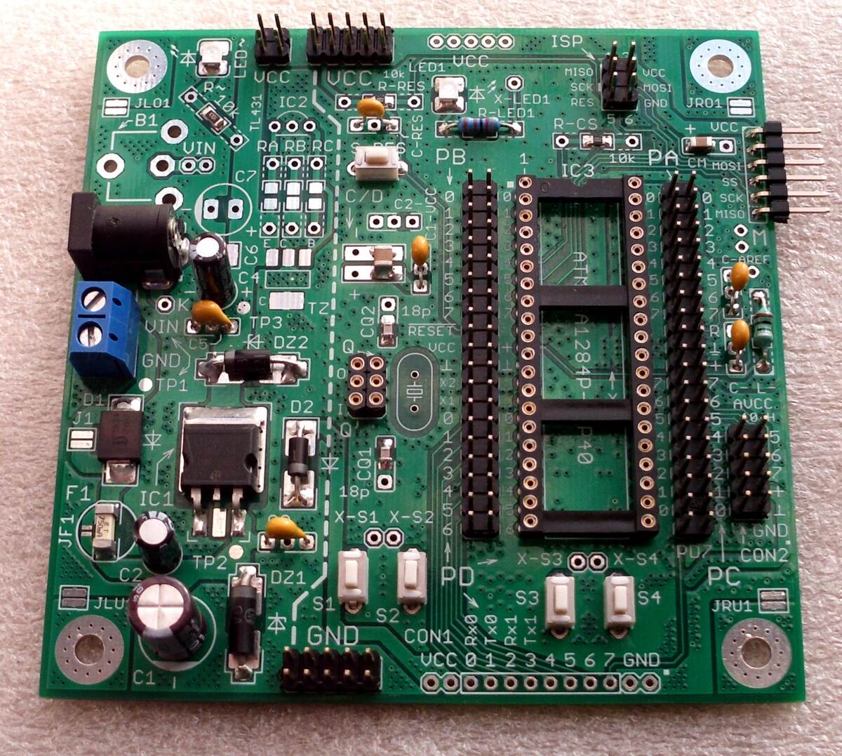
Bestückte grüne Leiterplatte mit Mikrocontroller-Anschlüssen
R-RES, R-CS, R-LED1, R-CS, UCC, 10k, IC3, PA, CM, MOSI, SS, 0, 1, 2, 3, 4, 5, 6, 7, CK, MISO, C-REF, ATmega128p, P40, X-S1, X-S2, X-S3, X-S4, PD, GND, CON2, PC, S3, S4, S1, S2, GND, CON1, UCC, 0, 1, 2, 3, 4, 5, 6, 7, GND, DZ1, DZ2, TP1, TP2, TP3, C1, C4, C5, C6, C7, C8, C9, IC1, IC2, JF1, JL01, JLU, JRU1
in „Entwurf USB-UART-Converter, KiCad, bitte um Review“ · Platinen · · Platinenfotos
-
 Bild
Bild
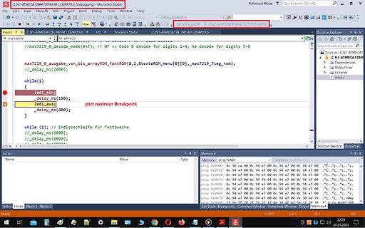
Microchip Studio Code Editor und Memory Ansicht
C_N1-ATMEGA128P_P40-M1_(324P20U) (Debugging) - Microchip Studio main.c //max7219_0_decode_mode(0xf); // if == Code B decode for digits 1-4, No decode for digits 5-8 while(1) { led1_ein; _delay_ms(150); led1_aus
in „welcher Debugger für 8bit Controller (AVR etc.) ?“ · Mikrocontroller und Digitale Elektronik · · Screenshots
-
Datei
mispav.cpp
Bit-Werte mit FC=16 empfangen * @version 2024-04-29 : 32-Bit-Werte mit FC=16 empfangen * weil 8 x 16 = 128 Worte * 4.8.1 C:/WinAVR/bin/avr-g++ -c -I D://h/home/cc/include -I C:/WinAVR/avr/include -gdwarf-2 -mmcu=atmega644p -Wall -Os -DAVR -DNPRGPATH=5 -DF_CPU=16008972UL -DLCD=2 -DLCD_YMAX=4 -DLCD_XMAX=20
in „Implementierung von Menüs auf alphanumerischen Displays“ · Mikrocontroller und Digitale Elektronik ·
-
Datei
test.c
SYSCLK 14745600UL //#define SYSCLK 4000000UL /* CPU clock in Hertz */ #ifndef UCSRB # ifdef UCSR1A /* ATmega128 */ # define UCSRA UCSR1A # define UCSRB UCSR1B # define UBRR UBRR1L # define UDR UDR1 # else /* ATmega8 */ # define UCSRA USR # define UCSRB UCR # endif #endif #include <avr/io.h> void xram(void
-
Datei
partlist.txt
100n C0805 rcl (30.1625 115.8875) R90 CON1 SCDA5A0201 SCDA5A0201 SCDA5A0201 (20.6375 30.48) R0 IC1 ATmega88-20P DIL28-3 atmel (37.465 50.165) R270 IC2 74S08D SO14 74xx-eu (18.0975 18.7325) MR90 IC3 FT232RL SSOP28 ftdichip (44.7675 21.59) R180 IC4 ATmega88-20P DIL28-3 atmel (20.32 99.695) R0 IC7 74AC08D
in „CP/M auf ATmega88“ · Mikrocontroller und Digitale Elektronik ·
-
Datei
millisek_demo.c
----------- millisek_demo.c --------------------------- Demo fuer Zeitmessung Millisekunde MCU : ATmega48 .. ATmega328 10.08.2016 R. Seelig -------------------------------------------------------------------- */ #include <avr/io.h> #include <avr/pgmspace.h> #include <avr/interrupt.h> #include <stdarg.h
in „Arduino Zeitmessung mit externes Modul das ms messen kann?“ · Mikrocontroller und Digitale Elektronik ·
-
PDF
fuseedit.pdf
selbiger in den einzelnen Funktionsgruppen, hier am Beispiel für den Mega8: <AVR name="m8" caption="ATmega8"> <Fuse name="RSTDISBL" bit="7" fuseByte="hfuse" default="1" desc="Select if PC6 is I/O pin or RESET pin" mode="expert"/> <Fuse name="WDTON" bit="6" fuseByte="hfuse" default="1" desc="Watchdog timer
in „Fuseeditor, grafische Benutzeroberfläche für AVRdude“ · Projekte & Code ·
-
Datei
AD_mit_Faktor.bas
seriell aus '---------------------------------------------------------- $regfile = "m8def.dat" 'ATmega8-Deklarationen $crystal = 3686400 'Quarz: 3,6864 MHz $baud = 9600 'Baudrate zum PC: 9600 Baud ' Ddrc = &B00000000 'PC7...PC0=0: PortC-Pins auf Eingang Admux = &B01100000 'Bits7+6=01: Aref ist intern
in „Register mit Faktor multiplizieren (Atmega8)“ · Mikrocontroller und Digitale Elektronik ·
-
Datei
lcdtest2.c
); LCD_setCursorPos(3, 0); LCD_write("test successful"); LCD_setCursorPos(2, 6); LCD_write("with ATmega128"); // PORTC |= (1<<PINC5); // delay(1000); // PORTC &= ~(1<<PINC5); while (1); return 0; }
in „Initialisierung M50530 LCD Display“ · Mikrocontroller und Digitale Elektronik ·
-
PDF
beispiele.pdf
SIG_INTERRUPT0 External interrupt1 function name: SIG_INTERRUPT1 External interrupt2 function name (ATmega): SIG_INTERRUPT2 External interrupt3 function name (ATmega[16]03) SIG_INTERRUPT3 External interrupt4 function name (ATmega[16]03): SIG_INTERRUPT4 External interrupt5 function name (ATmega[16]03): SIG_INTERRUPT5 External interrupt6 function name (ATmega[16]03): SIG_INTERRUPT6 External interrupt7 function name (ATmega[16]03): SIG_INTERRUPT7 Output compare2 interrupt function name: SIG_OUTPUT_COMPARE2 Overflow2 interrupt function name: SIG_OVERFLOW2
in „Messwerte in EEProm speichern“ · Mikrocontroller und Digitale Elektronik ·
-
PDF
haraleit.pdf
SIG_INTERRUPT0 External interrupt1 function name: SIG_INTERRUPT1 External interrupt2 function name (ATmega): SIG_INTERRUPT2 External interrupt3 function name (ATmega[16]03) SIG_INTERRUPT3 External interrupt4 function name (ATmega[16]03): SIG_INTERRUPT4 External interrupt5 function name (ATmega[16]03): SIG_INTERRUPT5 External interrupt6 function name (ATmega[16]03): SIG_INTERRUPT6 External interrupt7 function name (ATmega[16]03): SIG_INTERRUPT7 Output compare2 interrupt function name: SIG_OUTPUT_COMPARE2 Overflow2 interrupt function name: SIG_OVERFLOW2
in „avr bibliothek“ · Mikrocontroller und Digitale Elektronik ·
-
Datei
AVR8_Burn_O_Mat_Config.xml
caption="4.0V (3.7V - 4.5V)" Fuse1="0" Fuse2="0"/> </BrownOutDetection> <OscillatorOptions Type="ATmega8" /> </AVR> <AVR name="m16" caption="ATmega16"> <Fuse name="OCDEN" bit="7" fuseByte="hfuse" default="1" desc="Enable OCD (on chip debug)" mode="expert"/> <Fuse name="JTAGEN" bit="6" fuseByte="hfuse
-
Datei
Progmem_String_Test.c
// Test: // Grosse Datenblöcke im Flash // // z.B. hier für ATMega128 // by Arduinoquäler #include <avr/pgmspace.h> const char PROGMEM bigblock0[32767] = { "Block 0: The quick brow fox jumps over the lazy dog." }; const char PROGMEM bigblock1[32767] = { "Block 1:
in „ATMEGA128 Texte im Bootsektor definieren“ · Mikrocontroller und Digitale Elektronik ·
-
Datei
ADC.c
/* AVR Atmega 32 CPU = 16 */ init() } PORTB = 0b11111111; PORTA = 0b00000000; PORTD = 0b00000000; DDRA = 0b00000000; DDRB = 0b11111111; DDRD = 0b11111111; ADMUX = (0<<REFS0) | (0<<REFS1) | (1<<ADLAR); ADCSRA = 0b00000111; // Prescaler 128 ADCSRA = ADCSRA | 0b10000000; //ADC enable { send_str("ADC gestartet!\n"); ADMUX = (0<<REFS0) | (0<<REFS1) | (1<<ADLAR); ADCSRA = ADCSRA | 0b10000000; //enable ADC /*Dummy-Readout*/ ADCSRA |= (1<<ADSC
in „ADC Atmega 32“ · Mikrocontroller und Digitale Elektronik ·
-
PDF
Transistortester097k.pdf
Arbeitslisten-Kapitel 7 gesammelt. Inzwischen kann ich unter dem Linux Betriebssystem auch den EEprom-Speicher des ATmega8 einwandfrei beschreiben. 2 Kapitel 1 Eigenschaften 1. Arbeitet mit ATmega8, ATmega88, ATmega168 oder ATmega328 Mikrocontrollern. 2. Anzeige der Me▯ergebnisse auf einem 2x16 Zeichen LCD-Display. 3.
-
PDF
ch32v003_getting_started.pdf
Ardudino UNO / nano oder eines AVR-Systems mit zugänglichen GPIO-Pins und einer USB2UART Bridge. ATmega328, ATmega168, ATmega8 und ATtiny2313 sind in der Lage, die Firmware in den Programmer zu flashen. Übersicht der Schritte zum Aufbau des Selbstbauprogrammers und „erste Schritte“ bei der Programmierung
in „CH32V003: Selbstbauprogrammer und "Getting started"“ · Projekte & Code ·
-
Datei
main.c
***********************************************************/ /* definition for EEPROM memory for ATMega(16-128) and newer*/ /****************************************************************************/ uint8_t out = 0; /****************************************************************************/ /*
in „XMega und timer interrupt“ · Mikrocontroller und Digitale Elektronik ·
-
Datei
ad_mit_atm8.asm
; ad wandler mit atmega 8 ; achtung rcall mit stapel ; rjmp ohne stapel ;.nolist .include "m8def.inc" .list .def temp1=r18 ldi temp1, LOW(RAMEND) ; Stackpointer initialisieren out SPL, temp1 ldi temp1, HIGH(RAMEND) out SPH
in „ad_wandler an atmega 8“ · Mikrocontroller und Digitale Elektronik ·
-
Datei
qcnt_6led.c
/* 4-fach Flankenauswertung von Inkrementalgebern mit ATmega48/88 per Interrupt, Anzeige auf 6-stell. 7-Segmentanzeige und ser. Datenausgabe. Die um 90° phasenverschobenen Eingangssignale werden an INT0 (PD2) und INT1 (PD3) angelegt. Jede Flankenänderung wird
in „4-fach Flankenauswertung per Interrupt mit ATmega48/88“ · Projekte & Code ·
-
PDF
Using_the_Siemens_S65_Display.pdf
interaction is needed to generate this waveform with AVR processor. The code example below for the ATmega128 uses timer 2 with OC2 (PB7) for PWM generation. That means you can not use PB7 for LCD_RS any more (as in the circuit above). LCD_RS can be changed to PB5 for example. For the final running application
in „The Siemens S65 132x176, 65536 color display with AVR“ · Projekte & Code ·
-
PDF
Using_the_Siemens_S65_Display.pdf
interaction is needed to generate this waveform with AVR processor. The code example below for the ATmega128 uses timer 2 with OC2 (PB7) for PWM generation. That means you can not use PB7 for LCD_RS any more (as in the circuit above). LCD_RS can be changed to PB5 for example. For the final running application
in „The Siemens S65 132x176, 65536 color display with AVR“ · Projekte & Code ·
-
PDF
Using_the_Siemens_S65_Display.pdf
interaction is needed to generate this waveform with AVR processor. The code example below for the ATmega128 uses timer 2 with OC2 (PB7) for PWM generation. That means you can not use PB7 for LCD_RS any more (as in the circuit above). LCD_RS can be changed to PB5 for example. For the final running application
in „Reengineering: Siemens S65 Display“ · Mikrocontroller und Digitale Elektronik ·
-
Datei
Configuration_adv.h
(L6470) #define X2_MICROSTEPS 128 #define X2_OVERCURRENT 2000 #define X2_STALLCURRENT 1500 #define X2_MAX_VOLTAGE 127 #define X2_CHAIN_POS 0 #endif #if AXIS_DRIVER_TYPE_Y(L6470) #define Y_MICROSTEPS 128 #define Y_OVERCURRENT 2000 #define
in „Marlin 2.0.72 lässt sich nicht compilieren“ · Mikrocontroller und Digitale Elektronik ·
-
Datei
dude5.6_avr911.txt
Programmer : avr911 avr910_devcode (avrdude.conf) : 0x76 Overriding Baud Rate : 19200 AVR Part : ATMEGA8 Chip Erase delay : 10000 us PAGEL : PD7 BS2 : PC2 RESET disposition : dedicated RETRY pulse : SCK serial program mode : yes parallel program mode : yes Timeout : 200 StabDelay : 100 CmdexeDelay :
in „avrdude - Probleme unter Mac OS X 10.7 (Lion)“ · Mikrocontroller und Digitale Elektronik ·
-
Datei
Cinni-Regler_V1-1.c
Umdrehung // - Motorsteuerung mit Phasenanschnitt über // TRIAC-SolidStateRelais // HW: // - µC: Atmel ATmega8L-8PU // (8MHz / 2,7-5,5V / DIL28 schmal / -40...+85°C) // - Clock: 8 Mhz Quarz an XTAL1/XTAL2 // - PC0(ADC0,Pin23): Analogeingang Poti (=Sollwert) // rechts = kleinerer Wert // - PD0(RxD,Pin2)/PD1
in „Vorstellung Drehzahlregler mit Triac in Steckergehäuse“ · Mikrocontroller und Digitale Elektronik ·
-
Datei
__bootloader__do_spm__apipage.h
/* Dataformat of last page (only 256bytes on atxmega128a4u): * * Offset * 0x000 : 16 Jumpplaces for API (each 4 bytes) (see "__bootloader__apipage" for detail) * * ... no further specific format, yet ... * */ #ifndef SPMINTEREFACE_MAGICVALUE # ifdef USE_SPMINTEREFACE_MAGICVALUE
in „[XMega][C] Flash Write möglich aus Anwendung?“ · Mikrocontroller und Digitale Elektronik ·
-
Datei
NewBlink.c
Seiten erstellt. http://www.mikrocontroller.net war eine große Hilfe. * Ganz auf das Datenblatt des ATmega88PA konnte ich aber nicht verzichten. * * Heiko Jurgeleit, 19.03.2015 * jurgeleit.heiko(at)gmail.com * */ // CPU frequency for proper time calculation in delay function #define F_CPU 1000000UL #include
in „AVR - Drehgeber auslesen - optimiert für präzise Benutzereingaben“ · Projekte & Code ·
-
Datei
Inputs.ino
PIN_RESERVED 3 Encoder encoders[4]; // input pins autofilled based on which mpu #if defined(__AVR_ATmega1280__) || defined(__AVR_ATmega2560__) int inputPins[] = {A0, A1, A2, A3, A4, A5, A6, A7, A8, A9, A10, A11, A12, A13, A14, A15, 2, 3, 4, 5, 6, 7, 8, 9, 10, 11, 12, 13, 14, 15, 16, 17, 18, 19, 22, 23
in „Dauerkontakt vom Schalter in Impuls umwandeln“ · Analoge Elektronik und Schaltungstechnik ·
-
Datei
AVR8_Burn_O_Mat_Config.xml
caption="4.0V (3.7V - 4.5V)" Fuse1="0" Fuse2="0"/> </BrownOutDetection> <OscillatorOptions Type="ATmega8" /> </AVR> <AVR name="m16" caption="ATmega16"> <Fuse name="OCDEN" bit="7" fuseByte="hfuse" default="1" desc="Enable OCD (on chip debug)" mode="expert"/> <Fuse name="JTAGEN" bit="6" fuseByte="hfuse
-
PDF
RN-Mega_Board.pdf
bereits Erfahrungen mit AVR-Controllern haben oder denen die kleineren AVR´s wie Mega8/Mega32 oder Mega128 noch nicht ganz ausreichen bzw. zu wenig Reserven bieten. Dieses Modul nutzt den neusten Controllerchip ATMega2560. Er dürfte derzeit ohne Frage einer der leistungsfähigsten AVR Controller überhaupt
in „ATmega2560 spinnt“ · Mikrocontroller und Digitale Elektronik ·
-
Datei
iomxx0_1.h
*/ /* $Id: iomxx0_1.h 2235 2011-03-17 04:13:14Z arcanum $ */ /* avr/iomxx0_1.h - definitions for ATmega640, Atmega1280, ATmega1281, ATmega2560 and ATmega2561. */ #ifndef _AVR_IOMXX0_1_H_ #define _AVR_IOMXX0_1_H_ 1 /* This file should only be included from <avr/io.h>, never directly. */ #ifndef _AVR_IO_H
in „Tasterverarbeitung mit dem ARDUINO“ · Mikrocontroller und Digitale Elektronik ·
-
Datei
master.txt
// Master ATmega128 #include <avr/io.h> #include <stdint.h> #include <avr/interrupt.h> #ifndef F_CPU //#warning "F_CPU war noch nicht definiert, wird nun nachgeholt mit 4000000" #define F_CPU 8000000L // Systemtakt
in „Problem: SPI daten von mehreren slaves zum master! aber wie?“ · Mikrocontroller und Digitale Elektronik ·
-
Datei
ad_atm8.asm
; ad wandler mit atmega 8 ; achtung rcall mit stapel ; rjmp ohne stapel ;.nolist .include "m8def.inc" .list .def temp1=r18 ldi temp1, LOW(RAMEND) ; Stackpointer initialisieren out SPL, temp1 ldi temp1, HIGH(RAMEND) out SPH
in „ad_wandler an atmega 8“ · Mikrocontroller und Digitale Elektronik ·
-
Datei
Messung.s
--------------------------------- ; Titel : myAVR Beispiel "LCD Ausgabe auf einer Zeile" für den ATmega8 ;--------------------------------------------------------------------------- ; Funktion : gibt eine Zeichenkette auf dem myAVR LCD Modul, 1 Zeile ; Schaltung : PORTD.2 = RS, PORTD.3 = E, PORTD.4-7
in „ADC Messung funktioniert noch nicht“ · Mikrocontroller und Digitale Elektronik ·
-
Datei
main.c
//* LED fading test //* uses exponential PWM settings to achive visual linear brightness //* //* ATmega32 @ 8 MHz //* //* //***************************************************************************** #ifndef F_CPU /* In neueren Version der WinAVR/Mfile Makefile-Vorlage kann F_CPU im Makefile definiert
in „ATMega32 USART 16MHz (Pollin-Board)“ · Mikrocontroller und Digitale Elektronik ·
-
Datei
AVR8_Burn_O_Mat_Config.xml
caption="4.0V (3.7V - 4.5V)" Fuse1="0" Fuse2="0"/> </BrownOutDetection> <OscillatorOptions Type="ATmega8" /> </AVR> <AVR name="m16" caption="ATmega16"> <Fuse name="OCDEN" bit="7" fuseByte="hfuse" default="1" desc="Enable OCD (on chip debug)" mode="expert"/> <Fuse name="JTAGEN" bit="6" fuseByte="hfuse
-
Datei
V31AVR.C
// Einbinden der "Atmega16"-Definitionen #include <avr/io.h> #include <avr/interrupt.h> /* Definitionen */ #define W_Zeit 10 // W_Zeit = 10 bedeutet eine Zeit von 10 * 50ms = 0,5sec /* Definitionen Globaler Variablen */ char
in „8051-Code auf AVR-Platine STK500 übertragen“ · Mikrocontroller und Digitale Elektronik ·
-
Datei
ad_atm8.asm
; ad wandler mit atmega 8 ; achtung rcall mit stapel ; rjmp ohne stapel ;.nolist .include "m8def.inc" .list .def temp1=r18 ldi temp1, LOW(RAMEND) ; Stackpointer initialisieren out SPL, temp1 ldi temp1, HIGH(RAMEND) out SPH
in „ad_wandler an atmega 8“ · Mikrocontroller und Digitale Elektronik ·
-
Datei
uart.h
*********************************************************** uart.h - Gepufferte UART-Ausgabe für ATmega8 von Philipp Klostermann UBRR-Berechnung aus dem AVR-Tutorial von mikrocontroller.net Dieser Code dient nur einer Erläuterung und wird auf eigene Gefahr verwendet. Möglicherweise funktioniert er nicht
in „AVR Einstieg / Probleme mit Programm Interrupt“ · Mikrocontroller und Digitale Elektronik ·
-
Datei
hex_routinen.c
/* email: mike@microcontroller-starterkits.de */ /* Software: WinAVR to compile */ /* Hardware: ATMega128EvoBoard */ /****************************************************************************/ unsigned int hexatoi(const char * s); // wandelt einen 4-stelligen HEX-Code in unsigned long void itohexa
in „Wie wandelt ich Dez in Hex um?“ · Mikrocontroller und Digitale Elektronik ·
-
 Bild
Bild
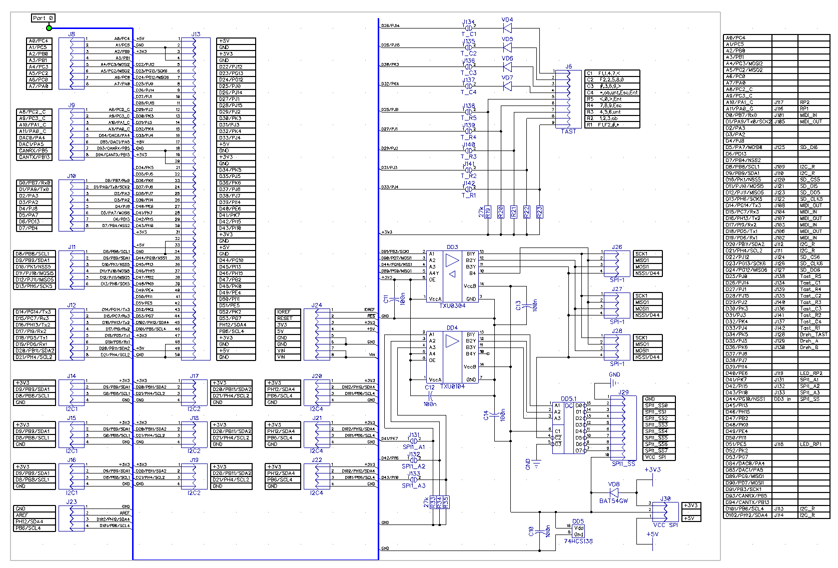
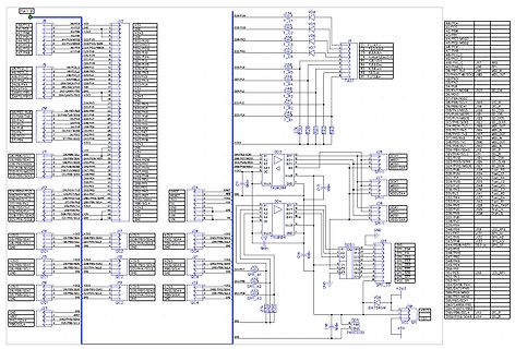
Schaltplan eines Mikrocontroller-Systems mit SPI und I2C
ATmega8, SPI, I2C, J13, J14, J17, J28, J24, J26, J34, J36, J38, J40, J42, J44, J46, J48, J50, J52, J54, J56, J58, J60, J62, J64, J66, J68, J70, J72, J74, J76, J78, J80, J82, J84, J86, J88, J90, J92, J94, J96, J98, J100, J102, J104, J106, J108, J110, J112, J114, J116, J118, J120, J122, J124, J126, J128, J130, J132, J134, J136, J138, J140, J142, J144, J146, J148, J150, J152, J154, J156, J158, J160, J162, J164, J166, J168, J170, J172, J174, J176, J178, J180, J182, J184, J186, J188, J190, J192, J194,
in „I2C Display einfache Frage“ · Mikrocontroller und Digitale Elektronik · · Schaltpläne
-
Datei
MEGA328P_Minicomputer_BASIC.bas
'BASIC-Minicomputer mit ATMega8 ' 'An PortD.3 - PortD.0 ist ein HD44780-kompatibles Display, Enable ist an 'PortB.1, RS ist an PORTB.0. 'An PortC.0 - PortC.3 und PortD.4 - PortD.7 ist eine Tastenmatrix. Bei 'PortD.4 - PortD.7 sind
in „Minicomputer mit BASIC-Interpreter“ · Mikrocontroller und Digitale Elektronik ·
-
Datei
timer.c
// ATMega128L - 8 MHz #include <avr/io.h> #include <avr/interrupt.h> volatile uint8_t timer0_sys_clk; volatile uint8_t bad_vec_cnt; // Initialisierung von Timer0, CTC-Mode, 1ms, ISR enable void init_timer0(
in „Probleme mit AVR Timer0 Interrupts“ · Mikrocontroller und Digitale Elektronik ·
-
Datei
test.c
/***************************/ //ATmega 88, CPU 10MHz #include <avr/io.h> #define F_CPU 10000000UL /***************************/ // Port void Port_Init() { DDRC|=(1<<PC5); } #define Port_Hi PORTC|=(1<<PC5) #define Port_Lo PORTC&=~(1<<PC5
in „ADC will nicht so recht“ · Mikrocontroller und Digitale Elektronik ·