-
PDF
e8_manual_5_July_2008.pdf
Out/PWM Out PWM2 Discrete Out/PWM Out Discrete Out/PWM Out Discrete Out/PWM Out PWM3 Discrete Out/PWM Out Discrete Out/PWM Out Discrete Out/PWM Out PWM4 Discrete Out/PWM Out Discrete Out/PWM Out Discrete Out
in „Vollprogrammierbare Zündanlage für 1Zylinder 2 und 4 Takt Motoren“ · Mikrocontroller und Digitale Elektronik ·
-
Datei
main2.c
/#define F_CPU 8000000UL #define Ledport PORTB #define R PB1 #define G PB2 #define B PB3 #define R_PWM OCR2 #define G_PWM OCR1A #define B_PWM OCR1B #define state 0 int my_delay(void); int main(void) { DDRB |= (1 << PB3); //PB3-PB1 als Ausgang DDRB |= (1 << PB2); DDRB |= (1 << PB1); PORTB &= ~(1 << PB3
in „RGB Fader Atmega8 Anfänger“ · Mikrocontroller und Digitale Elektronik ·
-
Datei
main.h
///////////////////////////////////////// #define ANLAUF_DUTY_CYCLE 20 // 0-100% von PWM, während dem Anlauf #define MINIMUM_DUTY_CYCLE 30 // 0-100% von PWM, direkt nach Anlauf #define PWM_FREQUENZ 20 // in khz ////////////////////////////////////////////////////////////////////////////
in „Brushless-Regler: Umschaltung Analog Komparator <-> ADC“ · Mikrocontroller und Digitale Elektronik ·
-
Datei
programm.txt
tn13def.inc" ;Include-Datei für Pseudonyme einbinden .def temp = r16 ;temporäres Register deklarieren .def pwm_periode = r17 ;Anzahl der PWM-Perioden pro Intensitäts-Wert .def ocr_wert = R18 ;Vergleichswert zur erzeugung des PWM-Signals .def betrieb = r19 ;Anzeige des Betriebszustands ;Bit0=0 -> aus, Bit0=1
in „µc-Programm für PWM und Schaltausgänge“ · Mikrocontroller und Digitale Elektronik ·
-
PDF
TD340.pdf
Figure 1 : Duty Cycle versus IN1 voltage Duty Cycle 100% Voltage 0% 1.2V 3.6V IN1 7/21 TD340 Figure 2 : PWM Analog and Digital Modes Vbatt Vbatt TD340 TD340 µP µP 5V M 5V M IN1 IN1 PWM PWM PWM PWM 0V 0V CF CF ANALOG INPUT PWM OUTPUT DIGITAL INPUT PWM OUTPUT + CF (270pF) + CF GROUNDED Active (synchronous)
in „Suche Vollbrücken Gatetreiber“ · Analoge Elektronik und Schaltungstechnik ·
-
Datei
main.c
<<PD7); PORTD|=(1<<PD5)+(1<<PD4)+(1<<PD6)+(1<<PD7); unsigned char i; usart0_init(); timer0_init(); pwm_init(); pwm_set_width(1024); pwm_set_val(100); pwm_direction(pwm_dir_1); unsigned int send,send2,send3; uint_fast8_t rec; usart_puts("restart\n"); while(1){ if(usart0_data_received()){ rec=usart0_getc(); //pwm_set_val(rec); //usart switch(rec){ case 0: pwm_direction(pwm_dir_0); break; case 1: pwm_direction(pwm_dir_1); break; case 2: pwm_react_shortcut(); break; case 3: pwm_direction(pwm_toshortcut); /* //
in „AVR: 16 Bit PWM funktioniert nur sporadisch“ · Mikrocontroller und Digitale Elektronik ·
-
Datei
uart_cmd.c
system->ADC_Value[6]); uart_puts(" 7: "); uart_putv(system->ADC_Value[7]); uart_puts("\n"); } //Soft PWM void cmd_pwm(char *cmd_buffer, uint8_t cnt, System_def *system) { unsigned char pwm=0, value=0; value = atoi(cmd_buffer+2); pwm = cmd_buffer[1] - '0'; if(value > 130){value=130;} if(pwm > 7){pwm=7;} pwm_setting[pwm] = pgm_read_word (&pwmtable_8D[value]); uart_puts("PWM Nr: "); uart_putv(pwm); uart_puts(" auf "); uart_putv(value); uart_puts("gesetzt"ENDLINE); pwm_update(); }
in „optimize Os / O0“ · Mikrocontroller und Digitale Elektronik ·
-
Datei
tiny1.ino
; volatile uint16_t seccount = 0; volatile uint16_t lastsec = 0; uint8_t daycount = 0; static void pwm_init(void) { DDRB |= _BV(PB0); // set PWM pin as OUTPUT TCCR0A |= _BV(WGM01) | _BV(WGM00); // set timer mode to FAST PWM TCCR0A |= _BV(COM0A1); // connect PWM signal to pin (AC0A => PB0) } /* When timer
in „AtTiny13: Watchdog Interrupt dauert lange“ · Mikrocontroller und Digitale Elektronik ·
-
Datei
main.c
(10k oder 100k) nutzen der den PWM-Pin nach Masse zieht. Wenn du die PWM abschalten möchtest schaltest du erst PB1 auf LOW und deaktivierst dann die PWM-Funktion des Pins PB1. * -------------------------------------------------------
in „Akku Spannung für 40W LED Lampe Kontrollieren“ · Mikrocontroller und Digitale Elektronik ·
-
Datei
ch552_keil.h
PIN_X 0x10 // UART0 alternate pin enable: 0=RXD0/TXD0 on P3.0/P3.1, 1=RXD0/TXD0 on P1.2/P1.3 #define bPWM2_PIN_X 0x08 // PWM2 alternate pin enable: 0=PWM2 on P3.4, 1=PWM2 on P3.1 #define bPWM1_PIN_X 0x04 // PWM1 alternate pin enable: 0=PWM1 on P1.5, 1=PWM1 on P3.0 #define bT2EX_PIN_X 0x02 // T2EX/CAP2 alternate
in „uC für 0,20€ CH552 / CH554 von WCH Billig Micro mit USB Funktion, Chip vorstellung“ · Mikrocontroller und Digitale Elektronik ·
-
Datei
ch552_keil.h
PIN_X 0x10 // UART0 alternate pin enable: 0=RXD0/TXD0 on P3.0/P3.1, 1=RXD0/TXD0 on P1.2/P1.3 #define bPWM2_PIN_X 0x08 // PWM2 alternate pin enable: 0=PWM2 on P3.4, 1=PWM2 on P3.1 #define bPWM1_PIN_X 0x04 // PWM1 alternate pin enable: 0=PWM1 on P1.5, 1=PWM1 on P3.0 #define bT2EX_PIN_X 0x02 // T2EX/CAP2 alternate
in „uC für 0,20€ CH552 / CH554 von WCH Billig Micro mit USB Funktion, Chip vorstellung“ · Mikrocontroller und Digitale Elektronik ·
-
Datei
Timer.txt
= CONTROL1; serial_asyn0_reg_ptr->sci0cr2 = CONTROL2; // ---start of program printf("start\n\r"); pwm_ptr = (PWMmodule*)ADDR_PWM; //PWM Base Address pwm_ptr->polarity = 0x01; //chan0 = high->low pwm_ptr->clock_select = 0xFF; // clock sa, sb ; bus_clock = 8MHz pwm_ptr->presc_clk_sel = 0x07; // clock a = bus_clock / 128 (62500Hz) pwm_ptr->scale_a = 0xFF; //(122Hz->8,16ms) pwm_ptr->scale_b = 0xFF; //(122Hz->8,16ms) pwm_ptr->period0 = 0xF5; //8,16ms*245=2s pwm_ptr->period1 = 0xF5; //8,16ms*245=2s pwm_ptr->period3 = 0xF5; //8,16ms*
in „Problem mit dem Timer eines HCS12“ · Mikrocontroller und Digitale Elektronik ·
-
PDF
DS8816A-05.pdf
® RT8816A Dual-Phase PWM Controller with PWM-VID Reference General Description Features The RT8816A is a 2/1 phase synchronous Buck PWM Dual-Phase PWM Controller controllerwhichisoptimizedforhighperformancegraphic Power
in „Spule auf Synchronwandler wird innerhalb sekunden brennend heiß“ · Analoge Elektronik und Schaltungstechnik ·
-
 Bild
Bild
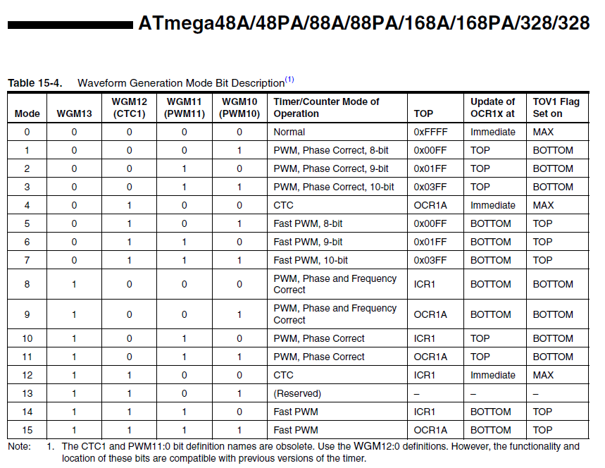
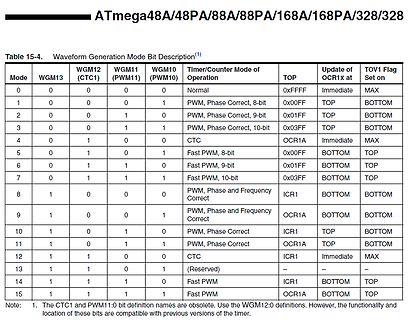
Tabelle der Waveform Generation Modi für ATmega-Mikrocontroller
PWM, 8-bit 0x00FF BOTTOM TOP 6 1 1 1 0 Fast PWM, 9-bit 0x01FF BOTTOM TOP 7 1 1 1 Fast PWM, 10-bit 0x03FF BOTTOM TOP 8 1 0 0 0 PWM, Phase and Frequency Correct ICR1 BOTTOM BOTTOM 9 1 0 0 1 PWM, Phase and Frequency Correct OCR1A BOTTOM BOTTOM 10 1 0 1 0 PWM, Phase Correct ICR1 TOP BOTTOM 11 1 0 1 1 PWM, Phase Correct OCR1A TOP BOTTOM 12 1 1 0 0 CTC ICR1 Immediate MAX 13 1 1 0 1 (Reserved) - 14 1 1 0 0 Fast PWM ICR1 BOTTOM TOP 15 1 1 1 Fast PWM OCR1A BOTTOM
in „ATmega Timer CTC ASM“ · Mikrocontroller und Digitale Elektronik · · Screenshots
-
Datei
Timer1_MEGA_8_16_32.html
Normal'; tT += ''; } if (RadioValue(document.Timer.radiobutton) == 'mode1') { tC += 'Timer1, Mode 1, PWM, Phase Correct, 8-bit'; tA += '(1 << WGM10)'; tAValue = 1; } if (RadioValue(document.Timer.radiobutton) == 'mode2') { tC += 'Timer1, Mode 2, PWM, Phase Correct, 9-bit'; tA += '(1 << WGM11)'; tAValue
in „Codegenerator Timer1 für Mega 8, 16, 32“ · Mikrocontroller und Digitale Elektronik ·
-
PDF
AVR335.pdf
buffer, while the first one is reloaded. Reading data from the DataFlash buffer is synchronized to the PWM frequency. Figure 6. Two Example PWM Cycles PWM Counter 8 7 6 5 4 3 2 1 PWM Cycle Number 0 1 2 3 4 5 6 7 8 7 6 5 4 3 2 1 0 1 2 3 4 5 6 7 8 7 6 5 4 3 2 1 0 4 AVR335 1456C–AVR–04/05 AVR335 The digital
in „PWM zur Tonausgabe auf einem Lautsprecher Mega8“ · Mikrocontroller und Digitale Elektronik ·
-
PDF
PCA9626.pdf
02h PWM0 7:0 IDC0[7:0] R/W 0000 0000* PWM0 Individual Duty Cycle 03h PWM1 7:0 IDC1[7:0] R/W 0000 0000* PWM1 Individual Duty Cycle 04h PWM2 7:0 IDC2[7:0] R/W 0000 0000* PWM2 Individual Duty Cycle 05h PWM3 7:
in „Probleme mit PCA9626 und I2C“ · Mikrocontroller und Digitale Elektronik ·
-
Datei
koax_pwm_01_06ms.asm
PWM input .equ PWM_IN1 = 4 .equ PWM_IN2 = 3 ; PPM output .equ PPM_OUT1 = 1 .equ PPM_OUT2 = 0 ; LED output .equ LED_OUT = 2 .equ PPM_MS_REL = 150 .equ PPM_PERIOD = 7 ; means 6-7 ms .equ CCM_AB_EN = (1<<OCIE0B
in „Ich bräuchte Assembler hilfe.“ · Mikrocontroller und Digitale Elektronik ·
-
PDF
ST10F27X_Flyer.pdf
10x10-bit 18Ch/8PWM 5 RTC/WDT 2 2 1 2 76 TQFP100 5V MAC p ST10F252 ● 256K 20K 48MHz 10x10-bit 18Ch/8PWM 5 RTC/WDT 2 2 1 2 76 TQFP100 5V MAC 1 ST10F252M ● 256K 16K 40MHz 16x10-bit 18Ch/8PWM 5 WDT 2 2 1 2 76 TQFP100 5V MAC ST10R252 ● 256K 12K 48MHz 10x10-bit 18Ch/8PWM 5 RTC/WDT 2 2 1 2 76 TQFP100 5V MAC ST10F269D ● 256K 12K 40MHz 16x10-bit 2x16Ch/4PWM 5 RTC/WDT 1 1 - 2 111 P(T)QFP 5V MAC ST10F271 ● 128K 12K 64MHz 24x10-bit 2x16Ch/8PWM 5 RTC/WDT 2 2 1 2 111 P(T)QFP
in „Programmer für C167“ · Mikrocontroller und Digitale Elektronik ·
-
PDF
ST10F27X_Flyer.pdf
10x10-bit 18Ch/8PWM 5 RTC/WDT 2 2 1 2 76 TQFP100 5V MAC p ST10F252 ● 256K 20K 48MHz 10x10-bit 18Ch/8PWM 5 RTC/WDT 2 2 1 2 76 TQFP100 5V MAC 1 ST10F252M ● 256K 16K 40MHz 16x10-bit 18Ch/8PWM 5 WDT 2 2 1 2 76 TQFP100 5V MAC ST10R252 ● 256K 12K 48MHz 10x10-bit 18Ch/8PWM 5 RTC/WDT 2 2 1 2 76 TQFP100 5V MAC ST10F269D ● 256K 12K 40MHz 16x10-bit 2x16Ch/4PWM 5 RTC/WDT 1 1 - 2 111 P(T)QFP 5V MAC ST10F271 ● 128K 12K 64MHz 24x10-bit 2x16Ch/8PWM 5 RTC/WDT 2 2 1 2 111 P(T)QFP
in „Ein kleiner Oberoncompiler für die C16x-Familie“ · Projekte & Code ·
-
PDF
181205_purewngs2pwm_db_de.pdf
x B x H in mm) 140 x 140 x 25 120 x 120 x 25 92 x 92 x 25 80 x 80 x 25 Lüfterdrehzahl (rpm) @ 100% PWM 1,000 1,500 1,900 1,900 Lautstärke (dB(A)) @ 100% PWM 19,8 20,2 19,6 19,2 Fördervolumen @ 100% PWM 61,2 / 104 51,4 / 87 33,15 / 56,02 26,3 / 44,45 (cfm / m3/h) Luftdruck @ 100% PWM (mm/H2O) 0,76 1,25
in „Frage zu 12V Lüfter“ · Mikrocontroller und Digitale Elektronik ·
-
PDF
AtmelCprogramming.pdf
allerdings bei anderen AVR-Controllern vergleichbar, die Pinbelegung allerdings nicht unbedingt. Um den PWM-Modus zu aktivieren müssen im Timer/Counter1 Control Register A TCCR1A die Pulsweiten-Modulatorbits PWM10 bzw. PWM11 entsprechend nachfolgender Tabelle gesetzt werden: PWM11 PWM10 Bedeutung 0 0 PWM-Modus
in „ATmega 8 und ohmisch messen“ · Mikrocontroller und Digitale Elektronik ·
-
PDF
Atmel.pdf
allerdings bei anderen AVR-Controllern vergleichbar, die Pinbelegung allerdings nicht unbedingt. Um den PWM-Modus zu aktivieren müssen im Timer/Counter1 Control Register A TCCR1A die Pulsweiten-Modulatorbits PWM10 bzw. PWM11 entsprechend nachfolgender Tabelle gesetzt werden: PWM11 PWM10 Bedeutung 0 0 PWM-Modus
in „RS232 direkt Anbindung“ · Mikrocontroller und Digitale Elektronik ·
-
PDF
AtmelCprogramming.pdf
allerdings bei anderen AVR-Controllern vergleichbar, die Pinbelegung allerdings nicht unbedingt. Um den PWM-Modus zu aktivieren müssen im Timer/Counter1 Control Register A TCCR1A die Pulsweiten-Modulatorbits PWM10 bzw. PWM11 entsprechend nachfolgender Tabelle gesetzt werden: PWM11 PWM10 Bedeutung 0 0 PWM-Modus
in „Suche gute möglichst Deutsche Doku zum C für AVR zu lernen“ · Mikrocontroller und Digitale Elektronik ·
-
PDF
AtmelCprogramming.pdf
allerdings bei anderen AVR-Controllern vergleichbar, die Pinbelegung allerdings nicht unbedingt. Um den PWM-Modus zu aktivieren müssen im Timer/Counter1 Control Register A TCCR1A die Pulsweiten-Modulatorbits PWM10 bzw. PWM11 entsprechend nachfolgender Tabelle gesetzt werden: PWM11 PWM10 Bedeutung 0 0 PWM-Modus
in „Tutorial mit sämtlichen Registererklärungen“ · Mikrocontroller und Digitale Elektronik ·
-
PDF
WTV020SD.pdf
FUNCTION 1 RESET RESET Reset pin 2 AUDIO-L DAC+ DAC audio output(+) to amplifier 3 NC NC NC 4 SP+ PWM+ PWM audio output to speaker 5 SP- PWM- PWM audio output to speaker 6 NC NC NC 7 P04 K3/A2/CLK Key /CLK in two line serial 8 GND GND Address pin 9 P07 K5/A4/SBT Key 10 P05 K4/A3/DI Key /DI in two line
in „Anfängerfrage 16 Bit seriell übertragen“ · Mikrocontroller und Digitale Elektronik ·
-
PDF
T302B_Brief_Release_v1.05.pdf
current (DC2DC) 1 VFBI I Feedback of Lamp current (LED or CCFL) 2 OLR I Open Lamp protection (CCFL) 3 PWM2 (PWM_DC) O PWM output for DC2DC 108 PWM3 (PWM_LED or VPWMN) O PWM output for LED or VPWMN for CCFL 110 Misc. X12MI I 12 MHz crystal input 20 X12MO O 12 MHz crystal output 21 SAR1 I SARADC for keypads
in „Übersicht über preisgünstige elektronische Geräte für reverse-engineering“ · Mikrocontroller und Digitale Elektronik ·
-
Datei
empfangen_uebung.c
void licht() { //Licht if(licht_ein == 50) { PORTB |= (1 << PB2); } else PORTB &= ~(1 << PB2); } void pwm_berechnung() { int wert1 = 0; if(pwm > 185) { wert1 = -(pwm-177); wert1 = ((wert1*4)+35); OCR1A = wert1; PORTB |= (1 << PB3); PORTB &= ~(1 << PB5); } if(pwm < 181) { wert1 = -(pwm-177); wert1 = ((wert1
in „Probleme mit UART“ · Mikrocontroller und Digitale Elektronik ·
-
Datei
Interrupts.c
CurFra != 1) { FrameHome(); } } else if(PIND & (1<<PD3)) //PCINT27 - Makes the Display darker { if (PWM_G == 255) { OCR1A = 127; PWM_G = 127; } else if (PWM_G == 127) { OCR1A = 63; PWM_G = 63; } else if (PWM_G == 63) { OCR1A = 0; PWM_G = 0; } } else if(PIND & (1<<PD4)) //PCINT28 - Makes the Display brighter { if(PWM_G == 0) { OCR1A = 63; PWM_G = 63; } else if(PWM_G == 63) { OCR1A = 127; PWM_G = 127; } else if(PWM_G == 127) { OCR1A = 255; PWM_G = 255; } } }
in „"Multiple Definition of." Warum?“ · Mikrocontroller und Digitale Elektronik ·
-
Datei
rc.h
change) extern volatile uint32_t rc_ppm_out[RC_PPM_OUT_NR_SERVOS+1]; void rc_ppm_out_init(void); /// PWM output /// #define RC_PWM_OUT_FREQ 80 #define RC_PWM_OUT_TIM_FREQ 1000000 #define RC_PWM_OUT_TIMER TIM3 // use this macro to set the motor commands // nr = 1..4, value = pwm signal in microseconds #define RC_PWM_SET_MOTOR_(nr) TIM_SetCompare ## nr #define RC_PWM_SET_MOTOR(nr, value) RC_PWM_SET_MOTOR_(nr)(RC_PWM_OUT_TIMER, value) void rc_pwm_out_init(void); #endif
in „RC Summensignal erzeugen“ · Mikrocontroller und Digitale Elektronik ·
-
PDF
ADCINCVR.pdf
of the PWM16 will be routed. Both parameters are set in the Device Editor. Table 15. Block PWM16_LSB: Register Output Bit 7 6 5 4 3 2 1 0 Value 0 0 0 0 0 0 0 0 Table 16. Block PWM16_MSB: Count Register DR0 Bit 7 6 5 4 3 2 1 0 Value Count(MSB) Count: PWM16 MSB down PWM. It can be read using the PWM16 API. Table 17. Block PWM16_LSB: Count Register DR0 Bit 7 6 5 4 3 2 1 0 Value Count(LSB) Count: PWM16 LSB down PWM. It can be read using the PWM16 API.
in „Beispiel Anwendungen/Application zu ADCs - Abtastrate & Auflösung“ · Mikrocontroller und Digitale Elektronik ·
-
Datei
led_fade_.asm
intcon,t0if goto t0_done movlw -(ISR_T0_US-2) ; addwf tmr0 movlw leds movwf fsr incf cnt0 movlw 256/PWM_STEPS addwf pwm bnc pwm_not_new_period bcf intcon,t0if ; temp flag decf cnt1 ; timer cnt1 stop after reaching 0 incfsz cnt1 incf cnt1 pwm_not_new_period movfw led movwf pwm_tmp bsf pwm_cnt,3 ; load 8 into pwm_cnt pwm_loop rrf pwm_tmp skpnc clrf 0 comf 0,w addwf pwm,w btfss intcon,t0if ; temp flag incfsz 0 skip decfsz 0 ; never skip incfsz 4 ; never skip decfsz pwm_cnt goto pwm_loop rrf pwm_tmp,w ; clock
in „LEDs an PIC ausglimmen lassen“ · Mikrocontroller und Digitale Elektronik ·
-
Datei
main.c
#define PWM_PORT PORTC #define F_CPU 12000000L // Systemtakt in Hz #define F_PWM 100 // PWM-Frequenz in Hz #define PWM_STEPS 90 // PWM-Schritte pro Zyklus(1..256) #define PWM_channels 3 #define T_PWM (F_CPU/(F_PWM*PWM_STEPS)) // Systemtakte pro PWM-Takt #if (T_PWM<(93+5)) #error T_PWM zu klein, F_CPU muss vergrösst werden oder F_PWM oder PWM_STEPS verkleinert werden #endif #include <avr/wdt.h> #include <stdint.h>
in „Probleme bei VUSB- Bachelorarbeit“ · Mikrocontroller und Digitale Elektronik ·
-
Datei
Test.asm
temp ; OCR1A mit 50 laden ldi temp, high(50) out OCR1AH, temp ldi temp, low(50) out OCR1AL, temp ; PWM Zähler zurücksetzen clr pwm_count1 clr pwm_count2 ; Compare Werte vorgeben ; LED 1 ldi led1h, high(0) ldi led1l, low(0) ; LED 2 ldi led2h, high(512) ldi led2l, low(512) ; LED 3 ldi led3h, high(1023)
in „10-Bit Soft-PWM geht nicht“ · Mikrocontroller und Digitale Elektronik ·
-
Datei
setup.c
CONFIG_BOARD_GRASSHOPPER_PWM1 { .name = "pwm1", .gpio = 1, }, #endif #ifdef CONFIG_BOARD_GRASSHOPPER_PWM2 { .name = "pwm2", .gpio = 2, }, #endif #ifdef CONFIG_BOARD_GRASSHOPPER_PWM3 { .name = "pwm3", .gpio = 3, }, #endif }; static struct gpio_led_platform_data pwm_led_data = { .num_leds = ARRAY_SIZE(pwm_led), .leds = pwm_led, }; static struct platform_device pwm_led_dev = { .name = "leds-atmel-pwm", .id = -1, .dev = { .platform_data = &pwm_led_data, }, }; #endif
in „Probleme mit ADS7846 beim NGW100“ · Mikrocontroller und Digitale Elektronik ·
-
Datei
setup.c
CONFIG_BOARD_GRASSHOPPER_PWM1 { .name = "pwm1", .gpio = 1, }, #endif #ifdef CONFIG_BOARD_GRASSHOPPER_PWM2 { .name = "pwm2", .gpio = 2, }, #endif #ifdef CONFIG_BOARD_GRASSHOPPER_PWM3 { .name = "pwm3", .gpio = 3, }, #endif }; static struct gpio_led_platform_data pwm_led_data = { .num_leds = ARRAY_SIZE(pwm_led), .leds = pwm_led, }; static struct platform_device pwm_led_dev = { .name = "leds-atmel-pwm", .id = -1, .dev = { .platform_data = &pwm_led_data, }, }; #endif
in „Grasshopper und USB-Host“ · Mikrocontroller und Digitale Elektronik ·
-
PDF
AS5410_Datasheet_EN_v2.pdf
, D3 PWMEn 0 Enables the PWM output D2-0 PWMPreScale<2:0> 0 PWM PreScale, Sets PWM frequency and resolution Figure 19: Single Pin Data Transmission Connection Diagram VDD= 3.0 - 3.6V 100nF VDD VDD AS5410 PWM
in „SPI funktioniert nicht“ · Mikrocontroller und Digitale Elektronik ·
-
PDF
irmck203.pdf
PwmConfig PwmPeriod (MSBs) 0xE (W) (W) (W) (W) PwmDeadTm 0xF (W) ModScl (LSBs) 0x44 (W) ModScl (MSBs) 0x45 (W) PwmGuardBand 0x51 (W) PwmConfig Write Register Map Field Access Field Description Name (R/W
in „BLDC, Synchronmaschine, Drehfeld Experimentierschaltung“ · Mikrocontroller und Digitale Elektronik ·
-
PDF
conradMuxPcb.pdf
MISO1/TX1/TOUCH A21/DAC0 A21 MuxA2 U3 K 2 U9 K 7 U15 K 1 2 39 Mux D4 1 R Mux D5 1 R Mux D6 1 R A 2/PWM 39/A20 MuxA3 B 3 3/PWM/CAN0TX/SCL2 38/A19/PWM/SDA138 MuxA4 6 6 6 C 4 4/PWM/CAN0RX/SDA2 37/A18/PWM/SCL137 MuxA5 C 1 3 1 3 1 3 5 36 C 11 C OUT P3 11 C OUT P9 11 C OUT P15 Inh 5/PWM/TX1/MISO1 36/A17/PWM MuxD2 A 10 A V X0 13 1 A 10 A V X0 13 1 A 10 A V X0 13 1 pin6 6 6/PWM 35/A16/PWM 35 MuxD3 B B 14 2 B B 14 2 B B 14 2 7 34 C 9 C X1 C 9 C X1 C 9 C X1 Rx3 7/PWM/RX3/MOSI0/SCL0 34/A15/CAN1RX/SDA0/RX5 Rx5 X2 15 3 X2 15 3 X2 15 3 Tx3 8 8/PWM/TX3/MISO0/SDA0 33/A14/CAN1TX/SCL0
in „Schaltplan richtig erstellen?“ · Analoge Elektronik und Schaltungstechnik ·
-
Datei
Original.c.c
dann { // dann schalte PWM1 und PWM2 _delay_ms(200); // auf 150, 200 und dann auf 250 PWM1 = 150; _delay_ms(200); PWM2 = 150; _delay_ms(200); PWM1 = 200; _delay_ms(200); PWM2 = 200; _delay_ms(200); PWM1 = 250; _delay_ms(200);
in „Ttiny 461a isp schaltung“ · Mikrocontroller und Digitale Elektronik ·
-
Datei
code.txt
#include <math.h> #define PWM 11 //PB3 #define left 9 //PB1 #define right 10 //PB2 #define minPWM 90 //minimal Duty-Cycle #define maxPWM 180 //maximal Duty-Cycle bool direction = true; int counter = 0; void setup() { // put your
in „H-Brücke es wird nur ein P-Fet extrem heiß“ · Analoge Elektronik und Schaltungstechnik ·
-
PDF
Akkulader_Beschreibung.pdf
rKeyRep = R8 ; Zähler für Tastenwiederholung ;.DEF rAdcV = R9 ; Betriebsspannungsmaske fr ADC .DEF rPwmC = R10 ; PWM Zähler .DEF rPwm1S = R11 ; PWM Schaltwert fr Kanal 1 .EQU cPwm1S = 11 ; (Pointerwert fr Kanal 1) .DEF rPwm2S = R12 ; PWM Schaltwert fr Kanal 2 .DEF rPwm3S = R13 ; PWM Schaltwert fr Kanal
in „2A 1s Li-ion Lader + Protection“ · Analoge Elektronik und Schaltungstechnik ·
-
Datei
main.c
Ausgang, serielle Schnittstelle (TxD) // Pin 2: Ausgang, An-Ausschalter Pumpe 1 // Pin 3: Ausgang, PWM Timer 2 // Pin 4: ungenutzt // Pin 5: Ausgang, PWM Timer 0 // Pin 6: Ausgang, PWM Timer 0 // Pin 7: Ausgang, An-Ausschalter Pumpe 2 PORTD |= (1 << PD0) | (1 << PD2) | (1 << PD4) | (1 << PD7); DDRD |
in „PWM mit Timer0 & 2 mit ATmega168PA läuft nicht“ · Mikrocontroller und Digitale Elektronik ·
-
Datei
main_mit_c.c
| (0<<MOTORA_2) | (1<<MOTORB_EN) | (1<<MOTORA_EN); abstand = HC_SR_04(); if (abstand >100) { MOTOR_PWM(50,50); } else if (abstand > 40 && abstand <= 100) { MOTOR_PWM(35,35); } else if (abstand <= 40 && abstand >5) { MOTOR_PWM(0,0); SERVO_LINKS; _delay_ms(250); links = HC_SR_04(); SERVO_RECHTS; _delay_ms
in „Externe .c bringt nur theater“ · Mikrocontroller und Digitale Elektronik ·
-
Datei
test.c
; // Skipped for this example // Initialize only GPAMUX and GPBMUX for this test EALLOW; // Enable PWM pins GpioMuxRegs.GPAMUX.all = 0x00FF; // EVA PWM 1-6 pins GpioMuxRegs.GPBMUX.all = 0x00FF; // EVB PWM 7-12 pins EDIS; // Step 3. Clear all interrupts and initialize PIE vector table: // Disable CPU
in „TIs und "DELAY_US()"“ · Digitale Signalverarbeitung / DSP / Machine Learning ·
-
Datei
lpc210x.h
0xE0008038)) #define TIMER1_EMR (*((volatile unsigned long *) 0xE000803C)) /* Pulse Width Modulator (PWM) */ #define PWM_IR (*((volatile unsigned long *) 0xE0014000)) #define PWM_TCR (*((volatile unsigned long *) 0xE0014004)) #define PWM_TC (*((volatile unsigned long *) 0xE0014008)) #define PWM_PR (*((
in „ARM: Absturz zur Laufzeit“ · Mikrocontroller und Digitale Elektronik ·
-
Datei
LED-Dimmen_2.asm
PortBy Eingang mit internen Pull-Up sbi DDRB,PLA ;Portpin für LED als Ausgang schalten... cbi DDRB ,PWM_1 ;PWM-Portpin als Eingang ohne... cbi PORTB,PWM_1 ;...internen Pull-Up-Widerstand LED = AUS ;...und somit gleichzeitig An ; ;Stackpointer initialisieren ; ldi A,low(RAMEND) ;Hier reicht ein Byte, weil
in „Wie generiere ich eine Pwm mit fester Frequenz aber variablem Tastverhältnis“ · Mikrocontroller und Digitale Elektronik ·
-
PDF
AXP202_PMU.pdf
Available Output Current PWM Mode 1800 mA VDC2OUT Output Voltage Range 0.7 2.275 V DCDC3 ILIM3 PMOS Switch Current Limit PWM Mode 1400 mA IDC3OUT Available Output Current PWM Mode 1000 mA VDC3OUT Output Voltage Range 0.7 3.5 V
in „LilyGo T-Watch 2020 v1 Micropython“ · Mikrocontroller und Digitale Elektronik ·
-
PDF
l9805e.pdf
1 0 1 0 1 0 0 1 FORWARD Full Bridge y 1 M W P 1 1 1 1 1 0 0 1 1 0 BACK Full Bridge e d M 1 1 0 1 1 pwm1 pwm1 pwm2 pwm2 PWM1 ->left Two Half 2 PWM2->right Bridges M W / M 1 1 1 1 1 pwm1 pwm1 pwm2 pwm2 PWM1 ->left Two Half W PWM2 ->right Bridges P Note: The DIR signal is internally synchronized with the
in „ST L9805-E Motortreiber mit H Brücke und ST7UD05 Kern“ · Mikrocontroller und Digitale Elektronik ·
-
Datei
fan.py
GPIO.BCM) #prepare switch GPIO port self.switchPin = 22 GPIO.setup(self.switchPin, GPIO.OUT) #prepare PWM GPIO port pwmPin = 27 GPIO.setup(pwmPin, GPIO.OUT) self.pwm = GPIO.PWM(pwmPin, 2000) #Notice: The target frequency for PWM on PC Ventilators is 25kHz. However, the Raspberry Pi 2, I am using for testing
in „PC FAN 4Port mit Raspberry Pi kontrollieren“ · Projekte & Code ·