-
Thread
FB7490: Selektives Mitschneiden ausgehender Daten
von der Pipe ein Problem mit dem Format. Ich nehme dann tcpdump. Letzte Zeile also z. B. ... =$SID| tcpdump -r - -w test.dmp Mit dem Filtern kann es bei tcpdump und dem Internetanschluss etwas schwierig werden. Also einfach noch eine Pipe nach tshark (von tcpdump aus geht das) und dann kann man Wireshark Display-Filter nehmen. Z. B.: ..., =$SID | tcpdump -r - -w - | tshark -r - -Y "udp.port == 53" filtert DNS. Das Shellskript beendet den Paketmitschnitt nicht. Das sollte man dann in der FritzBox machen.
-
Thread
433,92 MHz Fernbedienung mit Codeschloss brücken
Wenn du die SIDE Anschlüsse mit COM verbindest wird sich vermutlich nur eines der Tore öffnen. Einen Widerstand für die Verbindung zu nutzen ist eine gute Idee um einen Kurzschluss zu verhindern falls die Schaltung
-
Thread
PWM-Schaltung prüfen 3,3v zu 12V
/spoc-plus-2-multichannel-spi-high-side-power-controller/bts71040-4esa/
Source an +12V und Drain an den Ausgang. Infineon mit seinen N-Kanal MOSFETs in vielen Smart High-Side Switches (z.B. BTS50025) hat einfach keine Ahnung - oder was wolltest du sagen?
-
Thread
SSR DC DC 12V positiv geschaltet
Der passende Suchbegriff dafür wäre wohl "automotive high side switch", da findest du viele schöne Bauteile von diversen Herstellern.
-
Thread
Fritzbox 7950 WiFi 2,4GHz schlechter Empfang
das alte WLan bekannt waren kommen auf natürlich auf die neue Fritzbox drauf, da ja das alte WLAN (SID/PW) auf der neuen Box ist. Okay soweit? Nun nimmt er sich einen Zettel (Papier und Stift, du weißt schon) zur Hand und notiert sich von der alten Fritzbox (die er ja gerade abgebaut hat und in
-
Thread
MC33879 Freilauf
entnehmen, daß der Ausgang VPWR einen Schutz bietet. Zudem gibt es "Output voltage clamp, + 45 V (low side) and - 20 V (high side) during inductive switching". Für mich hört sich das so an, als ob das ausreicht? Da die Last ja mit beiden Klemmen nur mit dem MC33879 verbunden sind (Drain und Source) und
Freilaufdiode (für Motoren, Relais > usw.)? Nocht unbedingt "Output voltage clamp, +45 V (low-side) and -20 V (high-side) during inductive switching" hast du gefunden. Wegen der Anwendungsvariabilitat sind die Spannungen ab der sie einsetzen aber höher als sie es bei einer Freilaufdiode wären
-
Thread
Suche Board mit Shunt + Verstärker zur Strommessung bis 10mA
einen High-Side Shunt und einen Verstärker verwenden, fertig als INA240 o.ä. Bei 10mA reicht auch fast jeder OP, geschaltet als virtuelle Masse. https://www.elektronik-kompendium.de/public/schaerer/opa1.htm
Rainer W. schrieb im Beitrag #7735269: > Du könntest einen High-Side Shunt und einen Verstärker verwenden, fertig > als INA240 o.ä. Ah, sehr gut. Probiere ich aus. Vielleicht wäre der INA169 sogar noch besser geeignet weil ich da den Verstärkungsfaktor einstellen
-
Thread
dimensionierung von Kondensator gesucht
zur Folge) Gäbe es eine Möglichkeit das irgendwie herauszufinden? Ich wär für Tipps dankbar 'sid
der zweiten Sekundärwicklung (nördlich bei D102) verbunden... IC1 versorgung würd ich meinen. 'sid
-
Thread
Heckenschere defekt, brauche Hilfe bei Diagnose!
Sid schrieb im Beitrag #7733972: > Motorpole direkt mit 36V Spannung versorgt: führt zu Kurzschluss Was für ein Motor ist das? Photos! Photos! Photos!
Sid schrieb im Beitrag #7734115: > Hab den Motor ausgebaut: zunächst lässt sich nichts drehen, Na dann ist er hin, Lager festgefressen.
-
 Bild
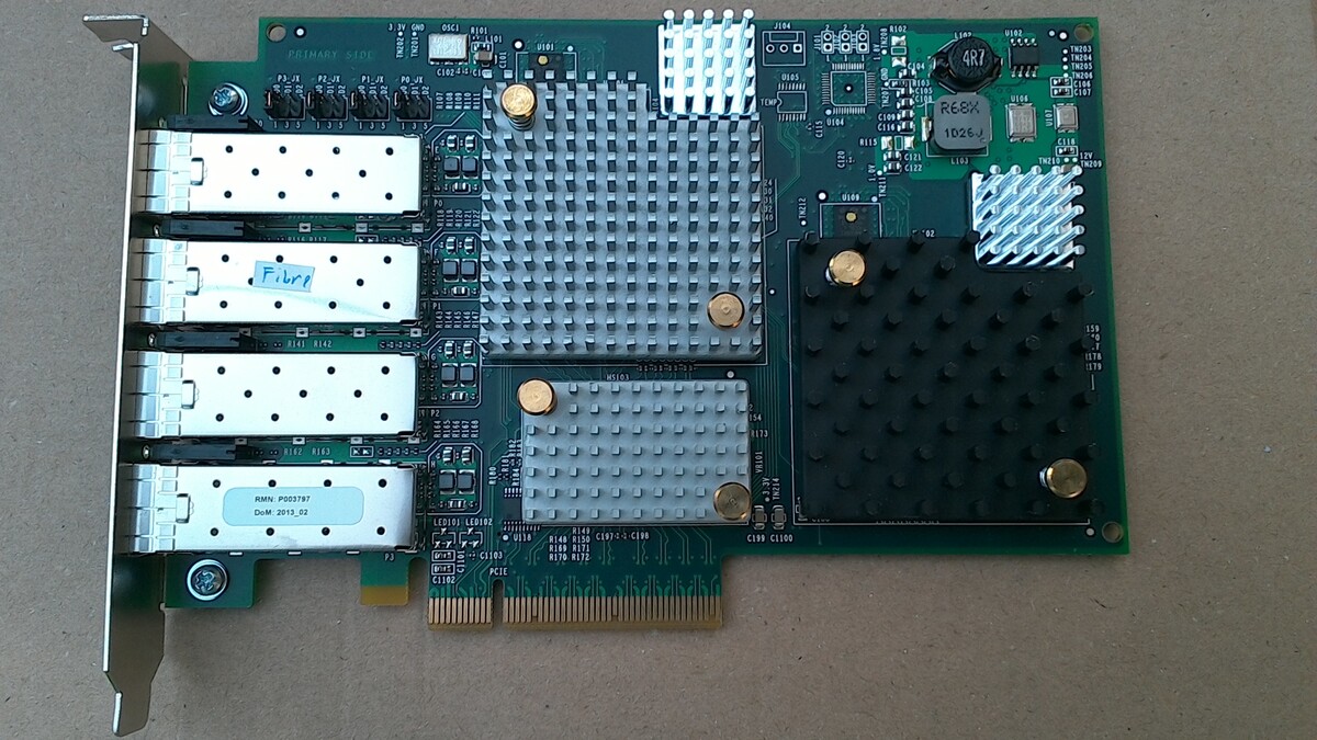
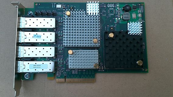
PCIe-Netzwerkkarte mit Kühlkörpern
PRIMARY SIDE, P1, P2, P3, P4, U102, U103, U104, U105, U106, R101, R102, R103, R104, R105, R106, R107, R108, R109, R110, R111, R112, R113, R114, R115, R116, R117, R118, R119, R120, R121, R122, R123, R124, R125, R126
-
 Bild
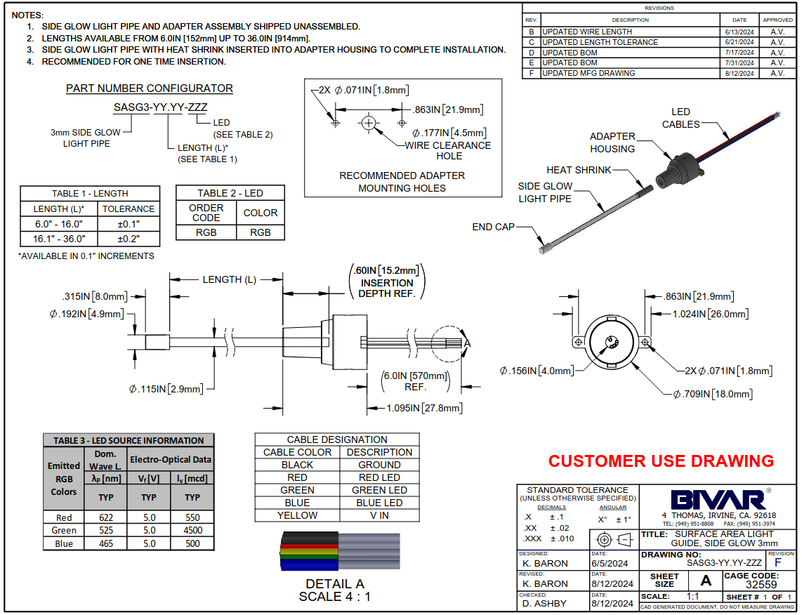
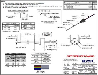
Technische Zeichnung einer LED-Leuchtleitung
NOTES: 1. SIDE GLOW LIGHT PIPE AND ADAPTER ASSEMBLY SHIPPED UNASSEMBLED. 2. LENGTHS AVAILABLE FROM 6.0IN [152mm] UP TO 36.0IN [914mm]. 3. SIDE GLOW LIGHT PIPE WITH HEAT SHRINK INSERTED INTO ADAPTER HOUSING TO COMPLETE
-
 Bild
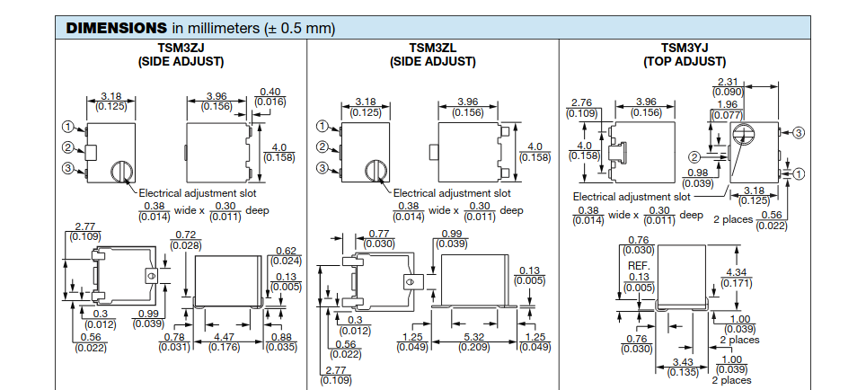
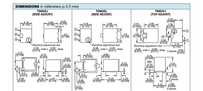
Technische Zeichnungen von TSM3ZJ und TSM3YJ Bauteilen
DIMENSIONS in millimeters (± 0.5 mm) TSM3ZJ (SIDE ADJUST) TSM3YJ (TOP ADJUST) Electrical adjustment slot 3.18 (0.125) 3.96 (0.156) 0.40 (0.016) 4.0 (0.158) 2.76 (0.109) 1.96 (0.077) 0.38 (0.014) wide x 0.30 (0.011) deep 0.72 (0.028) 0.62 (0.024) 0.13
-
 Bild
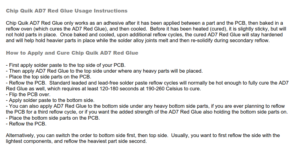
Gebrauchsanweisung für Chip Quik AD7 Red Glue
AD7 Red Glue also holding the bottom side parts on. - Place the bottom side parts on the PCB. - Reflow the PCB. Alternatively, you can switch the order to bottom side first, then top side. Usually, you want to first reflow the side with the lightest components, and reflow the heaviest part side second.

-
 Bild
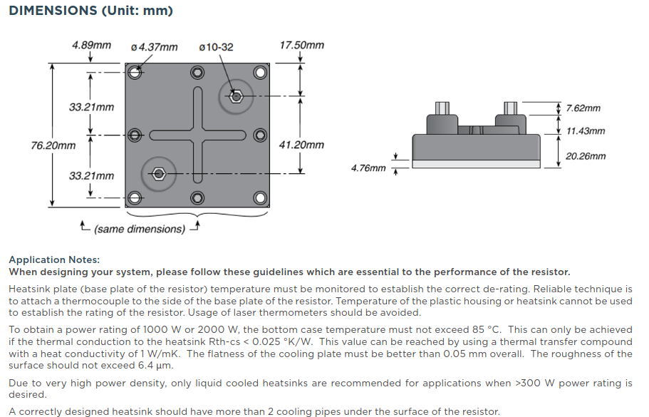
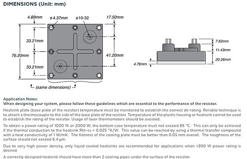
Technische Zeichnung und Anwendungshinweise eines Widerstands
monitored to establish the correct de-rating. Reliable technique is to attach a thermocouple to the side of the base plate of the resistor. Temperature of the plastic housing or heatsink cannot be used to establish the rating of the resistor. Usage of laser thermometers should be avoided. To obtain a power
-
Thread
StepUp Regler MC34063 steuern
deinen N-Kanal auf der High-Side bekommst du nicht ganz durchgesteuert (mess mal den Spannungsabfall am FET), mit dem P-Kanal kannst du sauber schalten. Es gibt auch viele Alternativen <100mOhm, z.B. bei Diodes gucken.
-
Thread
Umsetzung eines 5V Output mit ESP32 und AQY Halbleiterrelais
https://www.mouser.de/c/semiconductors/switch-ics/power-switch-ics-power-distribution/?type=High%20Side
alles Low-Side mit NPN (oder N-MOSFET). Ich denke, das ist bei KFZ der Normalfall. Nur die Beleuchtung ist High-Side geschaltet, aber rein mechanisch, an der Elektronik-Box vorbei. Ich habe früher öfter mal
-
 Bild
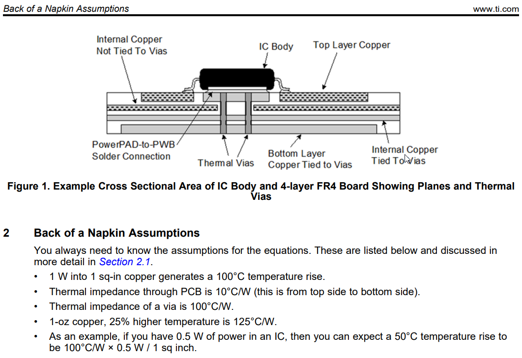
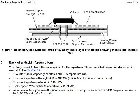
Querschnitt IC-Gehäuse und 4-lagige FR4-Leiterplatte mit Thermal Vias
copper generates a 100°C temperature rise. • Thermal impedance through PCB is 10°C/W (this is from top side to bottom side). • Thermal impedance of a via is 100°C/W. • 1-oz copper, 25% higher temperature is 125°C/W. • As an example, if you have 0.5 W of power in an IC, then you can expect a 50°C temperature
-
Thread
Sodastream Power - Servo defekt
doch an > Betriebs Reisen: 40º / der einen Seite Puls reisen 400us = Operating Travel: 40°/one side pulse traveling 400us Wenn das PWM Signal 1500us +-500us macht, dann macht das Servo wie beschrieben +-50º Ausschlag (400us = 40º). Das passt zu deiner Beobachtung. Ich würde sagen, falsches
-
Thread
kleine Spannung (µC) größere Spannung (13V) Highside schalten. Bauteil?
katalog/power-switches-schaltkreise_113433/?params=2613:1492961_integrierten-schaltkreises-art:high-side Wie zu erwarten, erschlägt mich die Vielfalt. Dirk F. schrieb im Beitrag #7726149: > Optokoppler Oh. Ich dacht bisher, das man damit nur LowSide schalten kann. Gibt es da spezielle Optokoppler
Dirk F. schrieb im Beitrag #7726149: >> Optokoppler > Oh. Ich dacht bisher, das man damit nur LowSide schalten kann. Gibt es > da spezielle Optokoppler? Oder ist dies gar nicht nötig? Ein Beispiel > Schaltbild für eine HighSide Schaltung? > Lass die da nichts einreden, Optokoppler verwendet man
-
 Bild
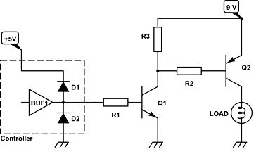
Schaltplan einer Transistor-Treiberstufe
+5V Controller BUF1 D1 D2 R1 Q1 R3 R2 Q2 9V LOAD
-
Thread
Ich suche ein Programm
"völlig exakt" zu emulieren. Das liegt in der analogen Natur der Sache. Schon zwei Exemplare eines SID aus derselben Charge waren nie völlig identisch.
-
 Bild
Foto einer Leiterplatte mit Detailvergrößerung eines Bauteils
09A1G F7002 B9011 >EP GW< SIDE B

-
 Bild
-
 Bild
Grüne Leiterplatte mit Lötstellen
M15-IUV-2 PIN SIDE IUV-2 401R79

-
Thread
Entwurf eines Abwärtswandlers
Bei 1A hat man schon hohe Verluste in der Shottky-Diode. Moderne Regler haben daher auch einen Low-Side FET, z.B. AP63205: https://www.digikey.de/de/products/detail/diodes-incorporated/AP63205WU-7/9858424
Peter D. schrieb im Beitrag #7723673: > Moderne Regler haben daher auch einen Low-Side FET Das (und Weiteres) hatte ich Serg zuvor *ebenfalls* gesagt. Scheint ihn nur _tatsächlich_ nicht zu interessieren ...
-
 Bild
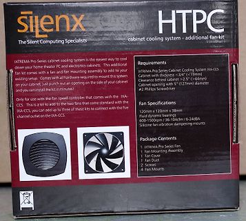
Verpackung eines Silenx HTPC Gehäuse-Lüfter-Kits
with all hardware required to mount this system on your cabinet, just punch out an opening on the side of your cabinet and you can install the kit in minutes! Only for use with the fan speed controller that comes with the IXA-CCS. This is a kit to add to the two fans that come standard with the IXA-CCS
-
Thread
Kleine Strombegrenzung
Danke an alle. Wir haben das nun mit einem Low Side Sense Widerstand und einem op-amp gelöst. Danke nachmals...
-
 Bild
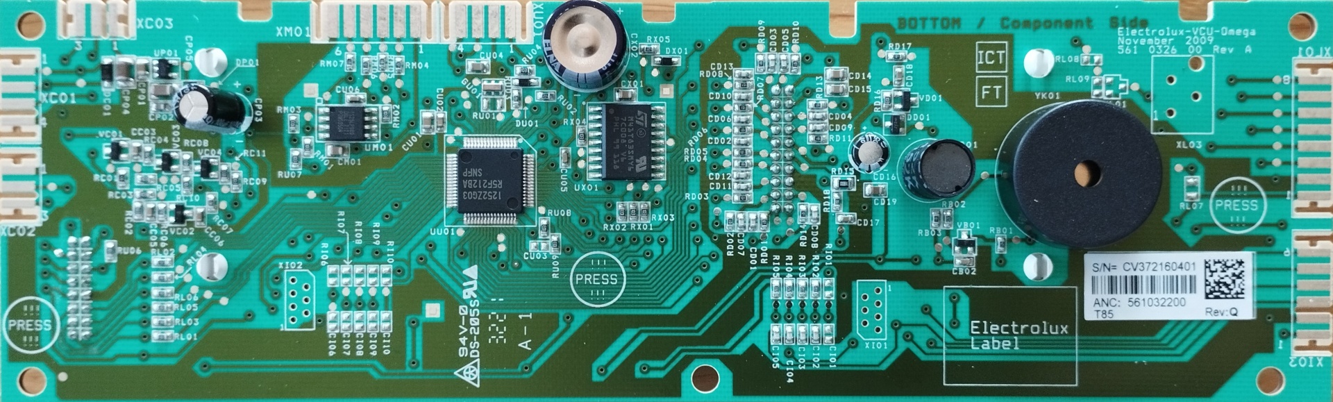
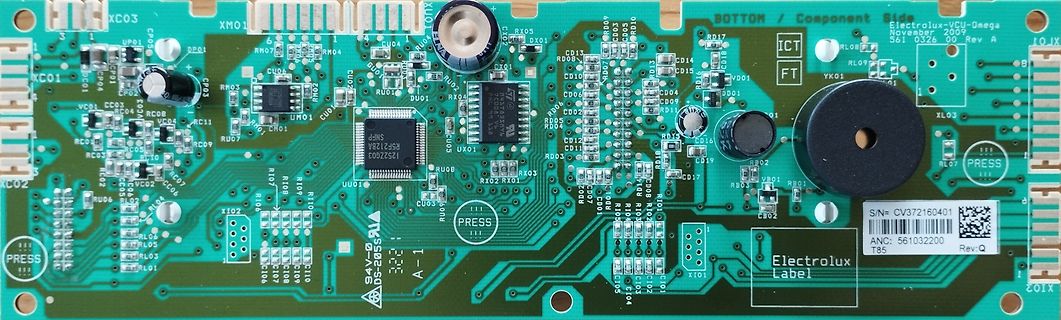
Bestückte grüne Leiterplatte von Electrolux
BOTTOM / Component Side Electrolux-VCU-Omega November 2009 561 0326 00 Rev A XC03 XM01 D101 RX05 UP01 CU01 RM04 RM03 C903 C902 C901 C904 C905 C906 C907 C908 C909 C910 C911 C912 C913 C914 C915 C916 C917 C918 C919 C920 C921
-
Thread
Relais mit UL2003A korrekt schalten
Der ULN2003 schaltet low-side!
-
 Bild
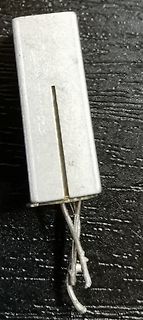
Metallgehäuse mit Drähten
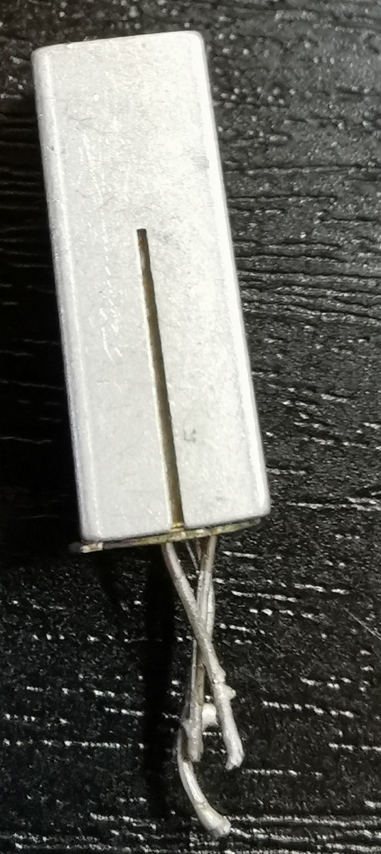
AC178_side.jpg
-
 Bild
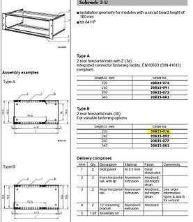
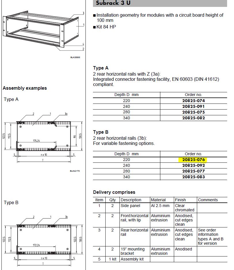
Technische Zeichnung und Tabelle eines Subracks
280 20825-077 340 20825-083 Delivery comprises Item Qty Description Material Finish Comments 1 2 Side panel Aluminium 2.5 mm Clear chromated 2 2 Fronthorizontal rail, with lip Aluminium extrusion Anodised, cut edges clean 3 2 Rear horizontal rail Aluminium extrusion Anodised, cut edges clean See order