-
PDF
doc4779atr2406.pdf
40 µs > 40 µs m > 50 µs n g D a TX_DATA Data g Pin 29 a m 3W_CLK Preamble (1-0-1-0) Pin 30 p ( 16/25 bits 16 bits 3W_DATA R > 200 µs > 200 µs Pin 31 t a 3W_ENA i Pin 32 S nOLE Pin 26 REF_CLK REF_CLK REF_CLK Pin 2 > 50 µs RX_ON Pin 24 TX_ON Pin 25 t u Data RX_DATA ( Pin 28 R VS m RSSI f valid signal
in „Gauss Anpassung Register“ · Mikrocontroller und Digitale Elektronik ·
-
PDF
lm3444.pdf
5% OnSemi BZX84C15LT1G 2 D2, D13 Diode, SCH, SOD123, 40V, 120 mA NXP BAS40H 4 D3, D4, D8, D9 Diode, FR, SOD123, 200V, 1A Rohm RF071M2S 1 D10 Diode, FR, SMB, 400V, 1A OnSemi MURS140T3G 1 D12 TVS, VBR = 144V Fairchild SMBJ130CA 1 R2 Resistor, 1206, 1%, 100 kΩ Panasonic ERJ-8ENF1003V 1 R3 Resistor, 1210,
in „High Brightness LEDs > 50W µC als regelbare KSQ“ · Mikrocontroller und Digitale Elektronik ·
-
PDF
Vishay_Tantal-faq.pdf
capacitor not exceed the derated value as provided in the relevant product datasheet. Axis Title 1.25 10000 o a R 1.00 g l 1000 e V 0.75 e n l e t d n a 1 n 2 R 0.50 2 t 100 o e 0.25 a C 0 10 0 25 50 75 100 125 150 175 Application Temperature (°C) 2nd line As an example, if a tantalum capacitor is used
in „Überspannungsschutz günstiger“ · Analoge Elektronik und Schaltungstechnik ·
-
PDF
bd4856.pdf
Ga BD48L31 Kn BD49L31 3.0V Ah BD48K30 Dd BD49K30 Fy BD48L30 Km BD49L30 2.9V Ag BD48K29 Dc BD49K29 Fr BD48L29 Kk BD49L29 2.8V Af BD48K28 Db BD49K28 Fp BD48L28 Kh BD49L28 2.7V Ae BD48K27 Da BD49K27 Fn BD48L27 Kg BD49L27 2.6V Ad BD48K26 Cy BD49K26 Fm BD48L26 Kf BD49L26 2.5V Ac BD48K25 Cr BD49K25 Fk BD48L25
in „Batterieschutzschaltung. Murks oder möglich?“ · Analoge Elektronik und Schaltungstechnik ·
-
PDF
infineon-bsb056n10nn3-g-datasheet-en.pdf
=C00 °C 1) - - 9 V GS0 V,T =2A °C,R thJA45 K/W 2) Pulsed drain current ID,pulse - - 332 A T C25 °C Avalanche energy, single pulse E - - 450 mJ I =30 A, R =25 AS D GS Gate source voltage V GS -20 - 20 V - - - 78 T C25 °C Power dissipation P tot - - 2.8 - T A25 °C, R thJA5 K/W 1) Operating and storage
in „Bauteilsuche Mosfet“ · Analoge Elektronik und Schaltungstechnik ·
-
PDF
ADuM5400.pdf
Ix DDx AC SPECIFICATIONS Output Rise/FallTime t /t 2.5 ns 10% to 90% R F Common-ModeTransient |CM| 25 35 kV/µs V IxV DD1 orV ISO CM= 1000V, Immunity 1 transient magnitude = 800V Refresh Rate fr 1.0 Mbps 1|CM|isthemaximumcommon-modevoltageslewratethatcanbesustainedwhilemaintainingO >0.7×DD1or0.7×VISOrahighoutputorV
in „ADUM5400 (Optokoppler) läuft nicht korrekt“ · Mikrocontroller und Digitale Elektronik ·
-
 Bild
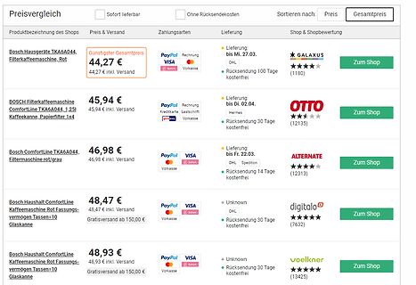
Preisvergleich für Bosch Filterkaffeemaschinen
Rücksendung 100 Tage kostenfrei GALAXUS (1180) Zum Shop BOSCH Filterkaffeemaschine ComfortLine TKA6A044, 1,25l Kaffeekanne, Papierfilter 1x4 45,94 € 45,94 € inkl. Versand PayPal Rechnung Kreditkarte Lastschrift qihpay Vorkasse Lieferung: bis Di. 02.04. Hermes Rücksendung 30 Tage kostenfrei OTTO (12135) Zum Shop
in „Kaffeemaschine defekt“ · Offtopic · · Screenshots
-
 Bild
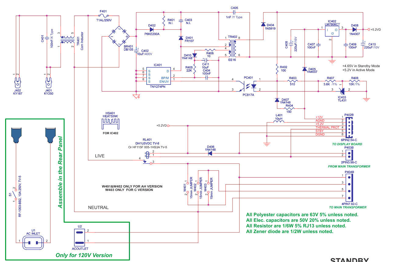
Schaltplan eines Schaltnetzteils
D402 R401 C403 N.I. C405 1nF / Type D404 1N5819 IC402 LM7806CT C407 100nF D408 1N407 C410 220uF D401 FR107 R406 10 1N4148 C411 100nF IC401 TNY274PN R405 22K PC401 R402 100nF R407 3.6K / 10 R408 10K / 1% D407 1N4148 R404 150 PC817 C409 100nF IC403 TL431 P402B +12V AGND +5.2V THERMAL PROT 5 S1BY DGND 6PNC
in „NAD Verstärker Stby Netzteil Problem“ · Analoge Elektronik und Schaltungstechnik · · Schaltpläne
-
Datei
20250418_Grundschlueler_Schulwindeln.txt
Entscheidung. „Windeln“ im Klassenzimmer: Steigt die Abhängigkeit von ... Frankfurter Rundschau https://www.fr.de › ... › Familie · Translate this page 3 Apr 2025 — Immer mehr Schüler im Grundschulalter sind noch auf Windeln angewiesen. Medizinische Ursachen sind eher die Ausnahme. Eltern beschweren sich, zum
in „Mitarbeiterfluktuation in Firmen“ · Ausbildung, Studium & Beruf ·
-
PDF
BT134W-SERIES_ENG_TDS.pdf
- K/W junction to ambient pcb mounted; pad area as in fig:14 - 70 - K/W STATIC CHARACTERISTICS Tj= 25 ˚C unless otherwise stated SYMBOL PARAMETER CONDITIONS MIN. TYP. MAX. UNIT BT134W- ... ...F ...G IGT Gate trigger current VD= 12 V; IT= 0.1 A T2+ G+ - 5 35 25 50 mA T2+ G- - 8 35 25 50 mA T2- G- - 11
in „Diac und Triac in einem Bauteil“ · Analoge Elektronik und Schaltungstechnik ·
-
PDF
FR5050_1.2_complete.pdf
50A DC brushed motor PWM speed controller DATASHEET FOR: Motor PWM FR5050 1.2 TECHNICAL SPECIFICATIONS: Supply voltage: 6-50V Output current: 100A peak 50A continuous at 25°C PCB version needs additional heatsink! Minimum duty cycle: 0% Maximum duty cycle: 100% Protections
in „suche Poti mit Rechts- und Linkslauf“ · Analoge Elektronik und Schaltungstechnik ·
-
PDF
D15G14E_14_030526.pdf
impedance(3)MV 2 - 1500 3000 Ω MV 2 LCDpowersupplyoutput impedance(4)1OUT Iout±100µA, T a25°C - 100 200 Ω V 1OUT Static current DDQ Ta=25°C - 0.5 5 µA VDDI, consumption V DD I2Q V 215.0V, Ta=25°C - 0.1 1 µA V2 I1Q V 12.5V, Ta=25°C - 0.5 5 µA V1 Operating current consumption (1)IDD 1/6 bias,
in „Nokia LCD 3510“ · Mikrocontroller und Digitale Elektronik ·
-
PDF
xx.pdf
Das Element Frau Element: Frau Symbol : Fr Entdecker : Adam (Jahreszahl unbekannt) Quantitative Analyse : Die durchschnittliche Masse beträgt 59, Isotope von 50 bis 110 sind bekannt. Durchschnittlicher Ionenradius 91-71-91 (mit Abweichungen von 63-25-51 bis 152-140-152) Vorkommen : Überall, wo Mann (Ma) zu finden ist, aber selten in dem sehr reaktiven, energiereichen unverheirateten Zustand. Reichhaltige Vorkommen in allen städtischen Gegenden, in
-
PDF
clt3.pdf
OUT 3 I3 0.75xLIM I3 ESD 0.25xLIM OVER 1.5mA VOLTAGE CURRENT LIMITER I LIM PROTECTION ESD 34 COM 34 ESD OVER CURRENT LIMITER I LIM 1.5mA VOLTAGE 0.25xLIM PROTECTION 0.75xLIM 4 I4 IN4 OUT 4 OPTO COUPLER DRIVER 2/10 CLT3-4BT6 FUNCTIONAL
in „Vergleichbarer Baustein zu CLT3-4B“ · Mikrocontroller und Digitale Elektronik ·
-
Datei
14_4_T13_I2C_PCF_LCD_MC.asm
******************** I2C_Star_Ack: cbi PortB, SDA ;start condition ldi count, 3 ;delay 10 cycles 1.25uS I2_Str0: dec count ; brne I2_Str0 ; ;============================ cbi PortB,SCL ;============================ ldi count, 3 ;delay 10 cycles 1.25uS I2_Str1: dec count ; brne I2_Str1 ; ;=============
in „AVR ATtiny13 I2C PCF8574 LCD Display Ansteuerung“ · Mikrocontroller und Digitale Elektronik ·
-
PDF
SS8050_D-2320098.pdf
SS8050 Rev. 1.1.0 S S Thermal Characteristics (1) 0 5 Values are aA T = 25°C unless otherwise noted. 0 — Symbol Parameter Value Unit N P Power Dissipation 1 W N PD E Derate Above 25°C 8 mW/°C p RθJA Thermal Resistance, Junction-to-Ambient 125 °C/W t a Note: i l 1. PCB size: FR-4, 76 mm x 114 mm x 1.57 mm (3.0 inch x 4.5 inch x 0.062 inch) with minimum land patternSsize. l c o Electrical Characteristics n r Values are aA T = 25°C unless otherwise noted. a s Symbol Parameter
in „LED Ansteuerung für Lazertag Projekt“ · Mikrocontroller und Digitale Elektronik ·
-
 Bild
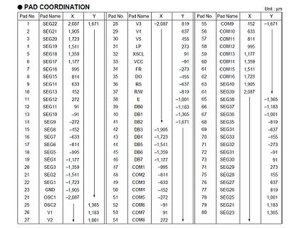
Tabelle der Pad-Koordinaten
SEG5 -995 19 SEG4 -1,177 20 SEG3 -1,359 21 SEG2 -1,541 22 SEG1 -1,723 23 GND -1,905 24 OSC1 -2,087 25 OSC2 1,365 26 V1 1,183 27 V2 1,001 28 V3 -2,087 819 29 V4 637 30 V5 455 31 LP 273 32 XSCL 91 33 VCC -91 34 FR -273 35 DO -819 36 RS -637 37 R/W -819 38 E -1,001 39 DB0 -1,183 40 DB1 -1,365 41 DB2 -1,671
in „PeakTech 4010 - Baugleich Metex?“ · Mechanik, Gehäuse, Werkzeug · · Screenshots
-
Datei
GETWDAY.INC
sbci a0, 0 ;use last year for jan. & feb. add r0, a0 ;+ 1.day of month lsr a0 lsr a0 add a0, r0 ;+ 0.25 add a0, day ;+ day _gwd1: subi a0, 7 brcc _gwd1 subi a0, -7 ;a0 = a0 % 7 ;0 = So, 1 = Mo, ... , 6 = Sa ret domonth: .db FD, FD+3, FD+2, FD+5, FD, FD+3 .db FD+5, FD+1, FD+4, FD+6, FD+2, FD+4 ;--------
in „Wochentag aus Datum berechnen auf ATMEL AVR“ · Mikrocontroller und Digitale Elektronik ·
-
PDF
VDO-Druckgeber-Pressure_Sensors.pdf
contact: max3 z W induktionsBrei z W max3 noninductiOe etriebstemperatur: ° 2z+C bis 1 A55+C (bis 1 A25+Crating temperature: ° 2z+C to 1 A55+C (up to 1 A25+C max3 A Std3 am 8nschßussgewinde) Bor A hour max3 at threaded connector) Widerstandsbereich: A5 Ω bis AR4 Ω vesistance range:A5 Ω to AR4 Ω Schaltbild
in „Druckgeber auswerten“ · Mikrocontroller und Digitale Elektronik ·
-
Datei
pse.txt
Titanium 23 5 4 V 50.942 4.30 51 6.74 Vanadium Vanadium 24 6 4 Cr 51.996 4.50 64 6.766 Chrom Chromium 25 7 4 Mn 54.938 4.10 0 7.435 Mangan Manganese 26 8 4 Fe 55.847 4.81 16 7.870 Eisen Iron 27 9 4 Co 58.933 5.00 64 7.86 Cobalt Cobalt 28 10 4 Ni 58.71 5.35 112 7.635 Nickel Nickel 29 11 4 Cu 63.546 5.10
-
Datei
report.txt
00 00 8C 30 | 0A D0 8A 20 E0 2D 10 10 3E 96 00 C4 8E 21 00 00 40 | 18 01 1D 80 D0 72 1C 16 20 10 2C 25 80 C4 8E 21 50 | 00 00 9E 01 1D 00 BC 52 D0 1E 20 B8 28 55 40 C4 60 | 8E 21 00 00 1E 8C 0A D0 90 20 40 31 20 0C 40 55 70 | 00 C4 8E 21 00 00 18 00 00 00 00 00 00 00 00 95 HEAD Revision: 3 Native DTDs
in „DVI-EDID Problem, Monitor wird nicht erkannt“ · Mikrocontroller und Digitale Elektronik ·
-
PDF
31-ab858785d62afdbe2d324f0ab-1.pdf
andtwllbeunderstoodthatinterial 23 and 24. Thssecured to makingthetrIpreertomountthebody9 ofthescrews25,anderesasacoverfns andissupportieve8onasutbleitue 20themotorassembly. Thisk23maybe whichmaylosupportthecup-shapedeleSecuredtothecylindereisofscrews aroundthesuppo. Asexplainoe,anorminsulatingdisk23maybeprovooe
in „Kontaktverschleiß bei elektr. Uhr zu groß“ · Analoge Elektronik und Schaltungstechnik ·
-
PDF
COG-BTHQ2165_I2C_LCD_Display.pdf
SPECIFICATIONS 4 3. INTERFACE SIGNALS 8 4. ABSOLUTE MAXIMUM RATINGS 8 4.1 ELECTRICAL MAXIMUM RATINGS (Ta=25qC) 8 4.2 ENVIRONMENTAL CONDITION 8 5. ELECTRICAL SPECIFICATIONS 9 5.1 TYPICAL ELECTRICAL CHARACTERISTICS 9 5.2 TIMING SPECIFICATIONS 10 6. CHARACTER SET ‘R’IN CGROM 12 VL-FS-COG-BTHQ21605-01 REV.A (BTHQ
in „Anschlußproblem I²C LCD an Atmega328P“ · Mikrocontroller und Digitale Elektronik ·
-
PDF
FU_Stoeber.pdf
UMGEBUNGSBEDINGUNGEN Betriebstemperatur 0 - +40 C (50 C siehe Tabelle 2-1, für Strom bei 50 C) Lagertemperatur -25 - +55 C Transporttemperatur -25 - +70 C Klimatische Beding. Klasse 3K3, wie in prEN50178 (1995) definiert Schutzart IP20, geeignet für Schaltschrankeinbau. Aufstellungshöhe Über 1000 m Leistungsreduktion
in „FU601/003 mit 0-10V ansteuern gelingt nicht“ · Analoge Elektronik und Schaltungstechnik ·
-
PDF
logicpkginfo.pdf
SN64BCT25*** DCT25*** DC*** SN74AS*** 74AS*** AS*** SN64BCT29*** DCT29*** DD*** SN74AVC*** AVC*** AVC*** SN74ABT*** ABT*** AB*** SN74AVC16*** AVC16*** CVA*** SN74ABT***–S ABT***–S AB***–S SN74AVC32*** AVC32***
in „IC Gesucht: 4040 CMOS“ · Mikrocontroller und Digitale Elektronik ·
-
PDF
deskline-dl5-dl6-system-montageanleitung-dt.pdf
70 / Tel.: +86 755 8610 6656 Tel.: 011-4303-8989 / 8900 Tel.: +86 755 8610 6990 E-Mail: linak@linak.fr +48 22 295 09 71 Fax: 011-4032-0184 E-Mail: sales@linak.cn www.linak.fr E-Mail: info@linak.pl E-Mail: info@novotecargentina.com www.linak.cn www.linak.pl www.novotecargentina.com Indien LINAK A/S India
in „Schreibtisch Linak Problem beim runter fahren“ · Mikrocontroller und Digitale Elektronik ·
-
PDF
ak4528vm-en-datasheet.pdf
De-emphasis Control Pin 21 DEM1 I De-emphasis Control Pin 22 VT - Output Buffer Power Supply Pin, 2.7 ∼ 5.25V 23 VD - Digital Power Supply Pin, 4.75 ∼ 5.25V 24 DGND - Digital Ground Pin 25 AOUTL− O Lch Negative Analog Output Pin 26 AOUTL+ O Lch Positive Analog Output Pin 27 AOUTR− O Rch Negative Analog Output
in „Daisy: Eingebettete Plattform für Audioprojekte“ · Mikrocontroller und Digitale Elektronik ·
-
PDF
001264678-da-01-en-DIODE_ZENER_2_7V_2_MM3Z2V7B_SOD_323F_ONS.PDF
Symbol Parameter Value Unit R θJA Thermal Resistance, Junction to Ambient 595 °C/W * Device mounted on FR-4 PCB minimum land pad. Electrical Characteristics TA= 25°C unless otherwise specified Symbol Parameter/ Test condition Min. Typ. Max. Unit VF Forward Voltage F I =10mA -- -- 1.0 V Package Marking and
in „Puffer für DCC-Dekoder mit Superkondensatoren“ · Projekte & Code ·
-
PDF
512410-sp-01-en-PROGRAM__SCHALTNETZTEIL_PSP_12010.pdf
-OUTPUTCONVERTER R21 CON2 DRV 5 4 3 2 1 5 4 3 2 1 +V +VDDIO R26 R17 R30 470E 2K2 6K8 R18 Q5 D 6 D R25 Q8 6 8 TX 8 5 B C1 B U5A 1K CN14 5K6 PC817 U5B 1 PC817 2 3 +V 2 4 R19 3PinSTM 4K7 R13 -V 6 5K6 8 Q3 C +VDDIO B +V 1 C D5 C R23 R16 D 4148W Q7 2 CN13 R21 2K2 10E R28 BC856 R20 1 4K7 1K 2 4 R15 1 RX 1K
in „Tipps zum Reparieren eines Voltcraft PSP12010“ · Analoge Elektronik und Schaltungstechnik ·
-
PDF
irl7833.pdf
Ratings Parameter Max. Units VDS Drain-to-Source Voltage 30 V VGS Gate-to-Source Voltage ± 20 I @ T = 25°C Continuous Drain CurrGS@ 10V 150f D C D @ TC= 100°C Continuous Drain CurrGS@ 10V 110f A I Pulsed Drain Current 600 DM PD@T C 25°C Maximum Power Dissipation 140 W P @T = 100°C Maximum Power Dissipation
in „Beschaltung Mosfet für Brushless-Regler“ · Analoge Elektronik und Schaltungstechnik ·
-
PDF
SeikoG642G_Pinbelegung.pdf
PIN 1 +12 PIN 1 VDD PIN 2 GND PIN 2 VSS PIN 3 M PIN 3 VLCD PIN 4 LR0 NC PIN 4 LP PIN 5 HSYNC PIN 5 FR PIN 6 LR1 NC NC PIN 6 N/C PIN 7 SCLK NC PIN 7 N/C PIN 8 BDSCLK NC PIN 8 DIN PIN 9 ECK NC PIN 9 XSC PIN 10 GND NC PIN 10 N/C PIN 11 LD0 PIN 11 UD0 PIN 12 BNCLK NC PIN 12 UD1 PIN 13 LD1 PIN 13 UD2 PIN
in „Saiko G642G Rev2 Display ansteuern (Signale)“ · Mikrocontroller und Digitale Elektronik ·
-
PDF
HF_H-Feld_Sonde_bis_1GHz.pdf
Amplitudendämpfunggerechnet werden. Die mechanischstabilere Ausführungdieser "Sniffer"-Spule aufeiner FR4- Leiterplatte erlaubt trotzdemeine sichere ReproduktionvonMessergebnissen! ImGegensatzzueiner HF-Prüfspitze (engl.:RF-Probe) muss nicht noch mühselignacheinemMasseanschluss inder zuprüfendenSchaltunggesucht
-
PDF
Referenz_Text.PDF
stamt von }lP, deshalb kommt ein lnJachbaunur für den eigenen Gebrauch in Frage. Prinüig: Ein 5ol'fr{zszillator T1 enthält einen kapaz,Ltiven Spannungs- teiler in der itückkopplungsschaltung, der von einen 8,2pF Kondensator gebildet und einer Kapazitätsdiode t:W3 wird", Ein Teii. d,er erzeugten HF-Leistung
in „AD8307. Wie die Leistung kalibrieren?“ · HF, Funk und Felder ·
-
PDF
ALS302.pdf
Φ0.81) Coppery Dielectric Foam PE 2.15±0.10 Natural Color 1 Outer Conductor Laminate Aluminum Tape 2.25±0.10 Silvery st 2 Outer Conductor 98%Copper Braid(112/0.10mm) 2.65±0.10 Silvery 3 Outer Conductor 97%Copper Braid(128/0.10mm) 3.05±0.10 Silvery Jacket FR-PVC 3.70±0.20 Black Physical Mechanical Specifications
in „Suche passenden RP SMA Stecker zum crimpen“ · Mechanik, Gehäuse, Werkzeug ·
-
PDF
UA702-Fairchild.pdf
Input Offset Voltage A S '; 2 k n 6.5 7.5 mV Average Temperature Coefficient AS - 50 n . 5.0 20 7.5 25 J.LV/"C of Input Offset Voltage TA = +70"C to O"C Input Offset Current 2.5 2.5 J.LA i Average Temperature Coefficient TA - 25 C to +70 C 4.0 10 3.0 8.0 nAI C of Input Offset Current T.A= 25°C to O"C
in „OPV mit nicht ganz symmetrischer Versorgung?“ · Analoge Elektronik und Schaltungstechnik ·
-
PDF
UA702-Fairchild.pdf
Input Offset Voltage A S '; 2 k n 6.5 7.5 mV Average Temperature Coefficient AS - 50 n . 5.0 20 7.5 25 J.LV/"C of Input Offset Voltage TA = +70"C to O"C Input Offset Current 2.5 2.5 J.LA i Average Temperature Coefficient TA - 25 C to +70 C 4.0 10 3.0 8.0 nAI C of Input Offset Current T.A= 25°C to O"C
in „µA702 - Der Urahne in der Simulation“ · Analoge Elektronik und Schaltungstechnik ·
-
PDF
datasheet_1_.pdf
t7 Latch pulse width Tc - 5 Tc - 4 ns t8 XECL falling edge setup time to FPSHIFT falling edge 0.25Tc -5 0.25Tc - 4 ns t9 XECL falling edge setup time from FPLINE rising edge 0.75Tc - 5 0.75Tc - 4 ns t10 XECL falling edge hold time to FPLINE falling edge Tc - 8 Tc - 8 ns t11 XECL pulse
in „Display Ansteuerung mit Epsonlohnenswert oder zu aufwendig?“ · Mikrocontroller und Digitale Elektronik ·
-
PDF
s1d13700.pdf
t7 Latch pulse width Tc - 5 Tc - 4 ns t8 XECL falling edge setup time to FPSHIFT falling edge 0.25Tc -5 0.25Tc - 4 ns t9 XECL falling edge setup time from FPLINE rising edge 0.75Tc - 5 0.75Tc - 4 ns t10 XECL falling edge hold time to FPLINE falling edge Tc - 8 Tc - 8 ns t11 XECL pulse
in „Quarz für S1D13700“ · Mikrocontroller und Digitale Elektronik ·
-
PDF
samsung_bn44-00195a_mk32p3_sch.pdf
CB852 2012 TDA4863G 2012 2012 6 2200uF RP802 SOP8 GND J801 RB802 10V 270KJ 6 3 3216 47R J 2012 CB803 0.25W 7 5 Z/D C/S 4 CP809 104K DZB801 RP803 473K DRAIN VCC 50V CB802 BZX84C30 RB803 240KJ 2012 7 2 2012 CB804 50VF SOT23 1R J 2012 CP808 2.2uF 2012 6 GND M/I 3 224K 50V RB857 16V DRAIN OCP 1KJ 2012 8 1 2012
in „? Reparatur Stromversorgung Samsung 245B“ · Analoge Elektronik und Schaltungstechnik ·
-
Datei
Analoge_Ein_Ausgabe.htm
> <td width="25%" align="center">0</td> <td width="25%" align="center">0</td> <td width="25%" align="center">0</td> <td width="25%" align="center">2</td> </tr> <tr> <td width="25%" align="center">0</td> <td width="25%" align="center">0</td> <td width="25%" align="center">1</td> <td width="25%" align="center">2</td> </tr> <tr> <td width="25%" align="center">0</td> <td width="25%" align="center">1</td> <td width="25%" align="center">0</td> <td width="25%
in „kurs in gcc“ · Mikrocontroller und Digitale Elektronik ·
-
PDF
BTS409L1.pdf
atTj= 25 °C, = 12 V unless otherwise specified bb min typ max Load Switching Capabilities and Characteristics On-state resistance (pin 3 to 5) IL= 1.8 A Tj=25 °C: R ON -- 160 200 m Tj150 °C: 320 400 Nominal load
-
PDF
MC74VHC1GT66-D.pdf
PHZ Delay, ON/OFF Control 3.0 28 35 40 45 to Analog Output (Figures 8, 15) 4.5 24 30 35 40 5.5 20 25 30 35 PZL, Maximum Propagation RL= 1000 W 2.0 32 40 45 50 ns PZH Delay, ON/OFF Control 3.0 28 35 40 45 to Analog Output (Figures 8, 15) 4.5 24 30 35 40 5.5 20 25 30 35 C Maximum Input ON/OFF Control
in „Widerstand nötig?“ · Mikrocontroller und Digitale Elektronik ·
-
Datei
20070716.txt
Extreme......: 0000 0 none - Precipitation: 010 2 30% - Switch.......: 0 - Temperature..: 111101 47 25°C - Unknown......: 10 <0011110010011100010000111000111110000001111010000000000000011010001110010011100000010101010000001010010110> IN - Data pack 1..: 00111100100111 - Data pack 2..: 00010000111000 -
in „AVR: Wetterinformationen über DCF77“ · Mikrocontroller und Digitale Elektronik ·
-
PDF
8051_Instructions.pdf
Comapre/Capture Unit E0H .7 .6 .5 .4 .3 .2 .1 .0 ACC 98H SM0 SM1 SM2 REN TB8 RB8 TI RI SCON C8 H T2PS I3FR I2FR T2R1 T2R0 T2CM T2I1 T2I0 T2CON 1) 2) F0H .7 .6 .5 .4 .3 .2 .1 .0 B 98H SM0 SM1 SM20 REN0 TB80 RB80 TI0 RI0 S0CON CC H .7 .6 .5 .4 .3 .2 .1 .0 TL2 3) 4) D0H CY AC F0 RS1 RS0 OV F1 P PSW 99 H .7 .6
in „Wieviel Zyklen pro Befehl??“ · Mikrocontroller und Digitale Elektronik ·
-
PDF
si3459bdv.pdf
A - 2.2 T A 70 °C - 1.8, b A Pulsed Drain Current DM - 8 Continuous Source-Drain Diode Current T C 25 °C I - 2.9 T A 25 °C S - 1.7, b T = 25 °C 3.3 C Maximum Power Dissipation T C 70 °C P 2.1 W T A= 25 °C D 2a, b a, b T A 70 °C 1.3 Operating Junction and Storage Temperature Range TJ, stg - 55 to 150
in „SMD Bauteil identifizieren "*"“ · Analoge Elektronik und Schaltungstechnik ·
-
PDF
NANO_BreakoutBoard_Stromlaufplan2.pdf
GND 4 GND R4 5 3 RESET D2 5 D2/PD2/INT0 R12 VCC 4 VCC D3 6 330R 6 D3/PD3/INT1 A7/ADC7 26 A7 5 A7 7 25 A6 330R D4 7 R5 8 D4/PD4/XCK/T0 A6/ADC6 24 A5 6 A6 D5 8 9 D5/PD5/T1 SCL/ADC5/PC5/A5 23 A4 R13 7 A5 D6 9 330R D6/PD6/AIN0 SDA/ADC4/PC4/A4 8 A4 D7 10 R6 10 D7/PD7/AIN1 ADC3/PC3/A3 22 A3 330R 9 A3 D8 11
in „Zeigt her eure Kunstwerke (2017-2019)“ · Projekte & Code ·
-
PDF
ITS4140.pdf
Datasheet Page 2 Rev. 2.1, 2006-07-24 ITS 4140N Maximum Ratings Parameter Symbol Values Unit at Tj= 25°C unless otherwise specified Supply voltage Vbb 60 V Load current (Short – circuit current, see page 5) IL self limited A Maximum current through the input pin (DC) I ±15 mA IN Junction temperature Tj
in „Wer kann dieses Bauteil identifizieren“ · Mikrocontroller und Digitale Elektronik ·
-
PDF
S20_EU.SCH.pdf
1 2 A C 1 10R|1W|D4L12V U . P10 A 2 3 1 6 A 1 2 2 3 5 5 pad4_55d2_75 1 0 C D7 A 4 4 1 OUT 2 1 C J FR102 C 1 | R M U12 . SMT 1 1 P2 R2 10A/3.6X10 2 3DG3001A1-H IW1700 1 pad4_55d2_75 VICFUSE Q2 3 3 C IW1700 1 1 1 1 2 2 L B 3 6 OUTPUT ASU 3 E 4 ISENSE VCC 1 1 C7 capy 5 R14 2 0 5 GND VSENSE 2 1 2 1 1 2
in „SonOff S20 Leben, wirken und widerbelebung. :-)“ · Haus & Smart Home ·
-
PDF
BFR93AR_1.pdf
crystal in a SOT37 package (BFR91A). [3] IMD = −60 dB (DIN 45004B);CI = 30 mA; CE = 8 V; L = 75 ; Tamb= 25 °C; Vp= VOat IMD = −60 dB; p = 795.25 MHz; Vq= VO−6 dB at fq= 803.25 MHz; Vr= VO−6 dB at r = 805.25 MHz; measured at p +qf −rf = 793.25 MHz [4] C = 30 mA; VCE= 8 V; RL= 75 ; amb = 25 °C; Vp= 200 mV at
in „KiCAD: SOT323 aus libcms scheint defekt zu sein“ · Platinen ·