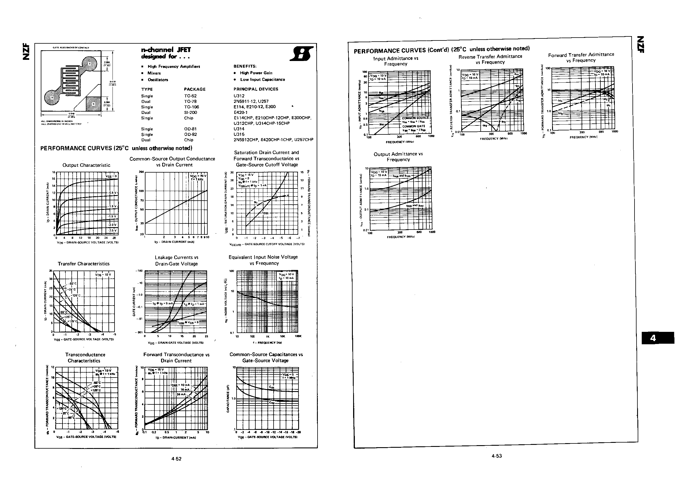
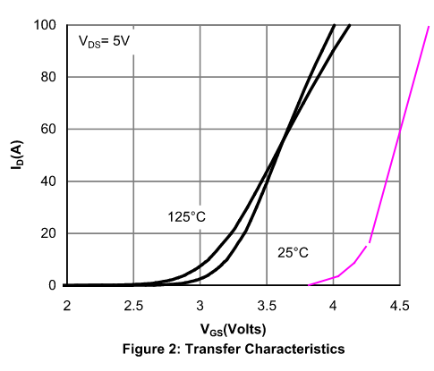
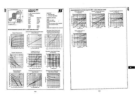
unless otherwise noted) Output Characteristic Common-Source Output Conductance vs Drain Current Transfer Characteristics Leakage Currents vs Drain-Gate Voltage Equivalent Input Noise Voltage vs Frequency Output Admittance vs Frequency Reverse Transfer Admittance vs Frequency Forward Transfer Admittance
, mit denen jeweils der CDC- oder HID-Modus aktiviert wird. Unter WindowsXP konnte man den Bulk-Transfer, welcher für den CDC-Modus benötigt wurde, im LowSpeed Betrieb illegalerweise noch freischalten, später ging aber auch das nicht mehr. Wenn dein Doper noch für CDC programmiert ist, wirst du ihn
Ingo W. schrieb im Beitrag #7445626: > weil ich der Meinung > war, dass Bulk-Transfer für Low-Speed Geräte illegal ist. Ist er definitiv. Deswegen haben ja auch alle relevanten OS die entsprechenden Bugfixes vorgenommen, damit diese illegalen Konfigurationen nicht mehr akzeptiert
M. Golzio, P. Dumond, S. Cros, and J. Teissié, “In vivo electrically mediated protein and gene transfer in murine melanoma,” Nat. [17] J.W. Loomis-Husselbee, P.J. Cullen, R.F. Irvine, and A.P. Dawson, Biotechnol., vol. 16, pp. 168-171, 1998. “Electroporation can cause artefacts due to solubilizaion
hatte ich auch bessere Angebote. Frueher waren das ganz viele. Als sich noch Angebote fuer den Transfer von Fluechtlingsvermoegen dazugesellten, wurden es innerhalb weniger Tage ganz wenige und blieb seit dem so.
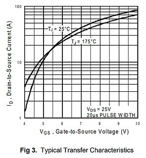
(V) VDS DRAIN-SOURCE VOLTAGE (V) GS D Figure 1.Typical Output Characteristic Figure 2. Typical Transfer Characteristic E C ) N ) 0.03 Ω 0.1 ( E A C C V N0.025 N D A V = 4.5V T 0.08 I GS I A S E E 0.02 R I = 7.0A - N 0.06 D O O E0.015 VGS= 10V E C R ID= 9.0A U U 0.04 O O - 0.01 - I I A R 0.02 D0.005
weiterlaufen können, während der PC auf die Daten zugreift. https://de.wikipedia.org/wiki/Media_Transfer_Protocol
Wie greife ich über den PC auf den Speicher des Smartphones zu? Das geht so nicht. MTP (media transfer protocol)-Devices werden unter Windows nicht als normale Laufwerke verwaltet. Die erscheinen nur im im Explorer in etwa so, als wären es welche. Dementsprechend gibt es im Shell-API die entsprechende
T (1) normally at conditions where current density is fairly uniform. ‰ where q = rate of heat transfer or power In some applications such as in RF power amplifiers and dissipation (D ) short-pulse applications, current density is not uniform and • h = heat transfer coefficient, … A = area involved in heat transfer, localized heating in the semiconductor chip will be the s T = temperature difference between regions of controlling factor in determining power handling ability. @ heat transfer. … Œ However, electrical
YUZ ® standard products shall ® also apply to such Bourns custom products. Users shall not sell, transfer, export or re-export any Bourns▯WYVK\J[Z▯VY▯[LJOUVSVN`▯MVY▯\ZL▯PU▯HJ[P]P[PLZ▯^OPJO▯PU]VS]L▯[OL▯ KLZPNU▯▯KL]LSVWTLU[▯▯WYVK\J[PVU▯▯\ZL▯VY▯Z[VJRWPSPUN▯VM▯U\JSLHY▯▯JOLTPJHS▯VY▯IPVSVNPJHS▯^LHWVUZ▯VY▯TPZZPSLZ
the bus Receiver The device which receives data from the bus Master The device which initiates a transfer, generates clock signals and terminates a transfer Slave The device addressed by the master 2 There are two signals associated with the I C bus: the Serial Clock Line (SCL) and the Serial DAta line
active high; SDOP active high; SPI1CON1 = 0x48; //SSET disabled; TXR required for a transfer; RXR data is not stored in the FIFO; SPI1CON2 = 0x03; //CLKSEL HFINTOSC; SPI1CLK = 0x01; //BAUD 15; SPI1BAUD = 0x3; TRISBbits.TRISB5 = 0; //SPI1_Open(); }
Boards dazu zu bringen, mit dem Timer Period Event des Master Timers einen synchronen DMA Burst Transfer auf die Compare Register der HRTIM TIMA, TIMB und TIMC durchzuführen. Die Compare Matches setze ich zum Erzeugen dreier unterschiedlicher PWM Signale ein, die jeweils ein komplementäres PWM Signal
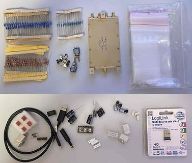
0.033 LogiLink. USB Bluetooth V4.0 Dongle class 1 up to 100m Distance low power consumption data transfer & linkage from phone to PC Bluetooth + EDR CSR LED
...........................................................18 Figure 8 - Definition of the data transfer condition .......................................................................................18 Figure 9 - Display data read back procedure - insertion of dummy read...........................
REVISION DESCRIPTION REV. DATE REMARK X01 INITIAL RELEASE 2012. 11. 01 A01 2013. 01. 31 Page 5, 15 & ■ Transfer from X version ■ Add the information of module weight 16 ■ Add tape ■ Add the packing specification - 2 - REV.: A01 2013/01/31 contained herein shall be disclosed to others or duplicated or used for
Wenn 1024 , stürzt sbTreeView gerne mal ab. hmm Auch wenn ich 512 einstelle, sehe ich bei data transfer in wireshark sowas: 7131 11.258490 host 2.10.2 USB 27 URB_INTERRUPT in 7132 11.259568 2.11.1 host USBMS 65563 SCSI: Data In LUN: 0x00 (Read(10) Response Data) 7133 11.259608 host
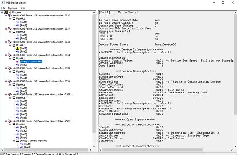
Beitrag #7422201: > das deutet ja auf einer ordentlichen Datenrate hin mit 65563 byte bulk > transfer. das zeigt nur dass du einen 64k Buffer hast. Die Größe der USB Transfers wird durch die EP Size im Descriptor bestimmt. Beispiel für einen 512B Sector Read: BulkOut > Sectorread BulkIn < 8
bit in the UCSRA register, it is possible to double the transfer rate, which is valid only in asynchronous mode Set this bit to "0" in step mode. Setting this bit will halve the division of the baud rate divider, effectively doubling the transfer rate of asynchronous
verfügung? 2 im FIFO + TXB? Frage 2 was ist gemeint mit " 1 = TxFIFO data is required for a transfer 0 = TxFIFO data is not required for a transfer " verstehe ich nicht ganz. Frage 3 BUSY bezieht sich ja auf das senden, verstehe ich es also richtig das mein Fifo leer sein kann und Busy high?
is written with ‘3’, the transfer will start with the SPIxTCNTL write. The two bytes in the TXFIFO will be sent after which the transfer will suspend until the third and last byte is written to SPIxTXB.
goal of compensation design is to shape 2. Choose the compensation capacitor (C3) to the converter transfer function to get a desired achieve the desired phase margin. For loop gain. The system crossover frequency applications with typical inductor values, setting where the feedback loop has the unity gain
of compensation design is to shape at the location of the ESR zero. Determine C6 the converter transfer function to get a desired by the equation: loop gain. The system crossover frequency C2 R ESR where the feedback loop has the unity gain is C6 = important. Lower crossover frequencies result R3 in
indicate that the cable will be online by 2030. The sea cable is projected to have the capacity to transfer 10.5 gigawatts (GW) of green electricity produced in Morocco’s Guelmim-Oud Nour region." Was stimmt denn nun? Alle anderen Quellen, incl die Seite, reden nur von 3,6GW! "The project’s budget
transmitting or receiving data, and they toggle at a fixed rate as specified in 3.1.3 GPIO when data transfer is in progress. Typically, these pins are connected to two LEDs to indicate data transfer. VIO/VIOHD CP2108 TX Toggle RX Toggle Figure 9.1. Transmit and Receive Toggle Typical Connection Diagram silabs.com
der FT230 einigermaßen clever gebaut ist enthält er einen großen Ringpuffer, der mit jedem USB-Transfer weiter aufgefüllt wird. Die Ausgabe-Blockgröße hätte dann also relativ wenig mit der Struktur der write() -Aufrufe zu tun. Mit einem USB-fähigen Mikrocontroller wär das ziemlich einfach umzusetzen
wird nicht in Echtzeit ermittelt? In der PC-Software muss praktisch zu jedem Zeitpunkt ein USB-Transfer aktiv sein (keine Pausen machen). Wenn auf dem Controller der Ringpuffer voll läuft (d.h. das DMX-Universum ändert sich langsam) sendest du einfach NAK auf dem betreffenden Endpoint bis wieder
kopieren. Christoph Z. schrieb im Beitrag #7418603: > Dafür darf USB bei einem > Isochronen Transfer auch Daten verlieren (so wie es bei IP/UDP z. B. > passieren darf). Kommt das in der Praxis denn auch vor? Bei UDP ist es zumindest solange man im LAN ist und die Auslastung hinreichend gering
Capacitance ––– 3400 ––– V = 0V iss GS Coss Output Capacitance ––– 1400 ––– pF VDS = -25V C Reverse Transfer Capacitance ––– 640 ––– ƒ = 1.0MHz, See Fig. 5 rss Source-Drain Ratings and Characteristics Parameter Min. Typ. Max. Units Conditions I Continuous Source Current MOSFETsymbol D S ––– ––– -74 (Body
, This bit will go high every time a data sample is dropped or repeated. DETC - D to E C-buffer transfer interrupt. Indicates the completion of a D to E C-buffer transfer. See “Channel Status and User Data Buffer Manage- ment” on page 38 for more information. RERR - A receiver error has occurred. The
Input Capacitance C iss 160 pF V =15 V, V =0V, Output Capacitance C 50 pF f=1MHz GS oss Reverse Transfer Capacitance C rss 30 pF SWITCHING(2) (3) Turn-On Delay Time td(on) 2.4 ns Rise Time tr 4.2 ns VDD =10V, D =0.93A R =6.2 , R =11 Turn-Off Delay Time td(off) 7.8 ns G D (refer to test Fall Time t 4.2
einen Breakpoint setzen und die Ergebnisse der 3 Aufrufe in 3 Variablen speichern - sich den Transfer mit einem Logikanalyzer direkt auf dem I2C Bus ansehen
Capacity 16Gbps Throughput 11.9Mpps Packet Buffer 1Mb MAC Address 2K Jumbo Frame 2048bytes Transfer Mode Store and forward Mean Time Between Failure 100000 hour Network protocol IEEE802.3 (10Base-T) IEEE802.3u (100Base-TX) IEEE802.3ab (1000Base-TX) IEEE802.3z(1000Base-FX) IEEE802.3x (Flow control
EverlightElec-EL357N_C_TA_G/C29981 Ginge dieser auch? Kurzer Vergleich zeigt dass hier die Current Transfer Ratio bei 50% liegt und bei dem PC817 bei 80% Sollte aber für den Pegel am uC nicht relevant sein?
wenn man in der Implementierung nicht gepennt hat. Atmel hat erst den Laden gekauft der Charge Transfer erfunden hat, hat es dann in die MCUs integriert und hat erschöpfend darüber geschrieben wie sowas zu integrieren ist. Stehendes Wasser geht natürlich prinzipbedingt nicht. Aber es sollte nun
Switching Unit A 6414 01016 Verschiedene zusätzliche Anschlußadapter und Verlängerungsleitungen Daten Transfer Software für D 6000 A 6899 00160 Screen Copy Software für D 6000 A 6899 00155 werden ebenfalls angeboten. Individuelle Lösungen sind möglich. Hinweis: Bei Verwendung des IEEE 488 Interfaces wird National
für die Devisen! Der im Wunschdenken 'Wichtigste' vielleicht, aber eben nicht der Grösste. Transfer-rubel wurden von denTiefrotbestrahlen Wirtschaftsmurkser auch schon mal als Devisen bezeichnet. Und natürlich wurde der Energieträger "Russen-Gas" mit einer Art Arbeitnehmer- und Techniküberlassung
iss Input Capacitance 520 pF C Output Capacitance V GSV, V =-DSV, f=1MHz 100 pF oss C rss Reverse Transfer Capacitance 65 pF R g Gate resistance V GSV, V =0DS f=1MHz 3.5 7.5 11.5 Q (10V) Total Gate Charge 9.2 11 nC g Q g4.5V) Total Gate Charge 4.6 6 nC V GS=-10V, VDS-15V, I D-6.5A Q gs Gate Source Charge
Switching speed Typical 0.2 ms 0.1 ms VIN= 5 V Turn off time* Toff IL= 100 mA Maximum 3.0 ms VL= 10 V Transfer Typical 0.8 pF f = 1 MHz characteristics I/O capacitance Ciso VB = 0 V Maximum 1.5 pF Initial I/O isolation resistance Minimum Riso 1,000 MΩ 500 V DC VIN= 5 V Maximum operating Maximum — 0.5 cps Duty
but are not limited to, airline regulatory controls, telecommunications regulations, technology transfer controls, and health and safety regulations. Each Member is solely responsible for the compliance by their Bluetooth™ Products with any such laws and regulations and for obtaining any and all required
DRV 2 VCR2_OUT B DRV U +6dB DRV MULTI MONI - RS232C D SPI signal TV IN NJM2296 p +6dB DRV 9 MAIN TRANSF TV_IN OSD BA7622 EX IR OUT LC74781 VCR1 IN (RC-6 Status) DSS_IN NJM2234 OSD/FL Cont VCR1 OUT LD_IN DC1 KEY MATRIX I RED STANDBY LED IR SENSOR Parallel port DVD_IN DC OUT1 NJM2234 CONT DC2 1 2 VCR2
jedem Takt weiter, und es werden alle 8 Takte Interrupts ausgelöst. CS geht erst am Ende des Transfer wieder auf inaktiven Zustand.
zwei SPIs mit mehr als 16 bit Datenbreite bietet? Die RSPIc der Renesas RX Familie können das >Transfer bit length is selectable as 8, 9, 10, 11, 12, 13, 14, 15, 16, 20, 24, or 32 bits. Z.B. R5F565N7ADFP https://mou.sr/3Hxw1el Grüße
instructions. Refer to "7.7.1 Function Set Command" for detail. 12 CU20049-UW2J 8.3.3 Serial data transfer Serial data can be inputted when the Strobe goes to "0". Serial data consists of 2 bytes. The first byte (Start Byte) consists of a total of 8 bits: the Synchronous bits (bit1-bit5), R/W (bit6), RS

 Bild
Bild
 Bild
Bild
 Bild
Bild
 Bild
Bild
 Bild
Bild
 Bild
Bild
 Bild
Bild