-
Datei
AT32MENU_Int_anzeige_Abfrage_Passwort.bas
Echtzeituhr Ddrd = &HFE Ddrb.1 = 1 Config Sda = Portc.1 ' I2C Bus konfigurieren Config Scl = Portc.0 Const Ds1307w = &HD0 ' Addresse der Ds1307 Uhr Const Ds1307r = &HD1 Config Clock = User '' Interne Time/Date Routinen für Bascom konfigurieren Config Date = Dmy , Separator = . ' *********** Konfiguration Ende
in „Variabeln ändern in ISR“ · Mikrocontroller und Digitale Elektronik ·
-
Datei
serieltest1.c
include <util/delay.h> #include "variablen.h" /* 9600 baud */ #define UART_BAUD_RATE 9600 #define DS1307 0xD0 //Adresse des DS1307 #define PCF_Write 0x70 //Adresse für PCF Porterweiterung schreiben #define PCF_Read 0x71 //Adresse für PCF Porterweiterung lesen #define MCP_Write 0xDC //Adresse MCP ADC schreiben
in „UART Schleife MC stürzt ab“ · Mikrocontroller und Digitale Elektronik ·
-
Datei
temp_str.c
TWCR & (1<<TWSTO))); #if defined(ARDUINO) #if ARDUINO >= 100 //check busy Wire.beginTransmission(DS1307_ID); printIIC(STATUS_REGISTER); Wire.endTransmission(); Wire.requestFrom( ( DS1307_ID ), 1); // request Status Register 1 Byte if ((readIIC() & 0x00ff) & (1<<BSY)) // auf busy pruefen mit 0x00ff unddieren
in „RTC DS3231 - Temperatur Daten?“ · Mikrocontroller und Digitale Elektronik ·
-
Datei
AT32MENU_Int_anzeige_Abfrage_Passwort.bas
Echtzeituhr Ddrd = &HFE Ddrb.1 = 1 Config Sda = Portc.1 ' I2C Bus konfigurieren Config Scl = Portc.0 Const Ds1307w = &HD0 ' Addresse der Ds1307 Uhr Const Ds1307r = &HD1 Config Clock = User '' Interne Time/Date Routinen für Bascom konfigurieren Config Date = Dmy , Separator = . ' *********** Konfiguration Ende
in „Servomotor ansteuern in Bascom“ · Mikrocontroller und Digitale Elektronik ·
-
Datei
serieltest1.c
include <util/delay.h> #include "variablen.h" /* 9600 baud */ #define UART_BAUD_RATE 9600 #define DS1307 0xD0 //Adresse des DS1307 #define PCF_Write 0x70 //Adresse für PCF Porterweiterung schreiben #define PCF_Read 0x71 //Adresse für PCF Porterweiterung lesen #define MCP_Write 0xDC //Adresse MCP ADC schreiben
in „UART Schleife MC stürzt ab“ · Mikrocontroller und Digitale Elektronik ·
-
Datei
serieltest1.c
include <util/delay.h> #include "variablen.h" /* 9600 baud */ #define UART_BAUD_RATE 9600 #define DS1307 0xD0 //Adresse des DS1307 #define PCF_Write 0x70 //Adresse für PCF Porterweiterung schreiben #define PCF_Read 0x71 //Adresse für PCF Porterweiterung lesen #define MCP_Write 0xDC //Adresse MCP ADC schreiben
in „UART Schleife MC stürzt ab“ · Mikrocontroller und Digitale Elektronik ·
-
Datei
serieltest1.c
include <util/delay.h> #include "variablen.h" /* 9600 baud */ #define UART_BAUD_RATE 9600 #define DS1307 0xD0 //Adresse des DS1307 #define PCF_Write 0x70 //Adresse für PCF Porterweiterung schreiben #define PCF_Read 0x71 //Adresse für PCF Porterweiterung lesen #define MCP_Write 0xDC //Adresse MCP ADC schreiben
in „UART Schleife MC stürzt ab“ · Mikrocontroller und Digitale Elektronik ·
-
Datei
serieltest1.c
include <util/delay.h> #include "variablen.h" /* 9600 baud */ #define UART_BAUD_RATE 9600 #define DS1307 0xD0 //Adresse des DS1307 #define PCF_Write 0x70 //Adresse für PCF Porterweiterung schreiben #define PCF_Read 0x71 //Adresse für PCF Porterweiterung lesen #define MCP_Write 0xDC //Adresse MCP ADC schreiben
in „UART Schleife MC stürzt ab“ · Mikrocontroller und Digitale Elektronik ·
-
Datei
serieltest1.c
include <util/delay.h> #include "variablen.h" /* 9600 baud */ #define UART_BAUD_RATE 9600 #define DS1307 0xD0 //Adresse des DS1307 #define PCF_Write 0x70 //Adresse für PCF Porterweiterung schreiben #define PCF_Read 0x71 //Adresse für PCF Porterweiterung lesen #define MCP_Write 0xDC //Adresse MCP ADC schreiben
in „UART Schleife MC stürzt ab“ · Mikrocontroller und Digitale Elektronik ·
-
Datei
l__fung.bas
Bewegung Alias Pind.7 Config Sda = Portc.1 '##### I2C Bus konfigurieren Config Scl = Portc.0 Const Ds1307w = &HD0 '##### Addresse der Ds1307 Uhr Const Ds1307r = &HD1 Config Clock = User '##### Interne Time/Date Routinen für Bascom konfigurieren Config Date = Dmy , Separator = . Const Pause = 150 '#####
in „Ds1307 bleibt einach stehen?“ · Mikrocontroller und Digitale Elektronik ·
-
Datei
ds1307.c
#include <p18cxxx.h> #include <i2c.h> #include "ds1307.h" void DS_settime_array(char* time){ DS_settime(&time[0], &time[1], &time[2]); } void DS_settime(char* hour, char* min, char*sec) { // es wird keiner AM/PM Darstellung verwendet char raw[]= {0,0,0
in „PIC: HW I2C & SW SPI gemeinsam nutzen“ · Mikrocontroller und Digitale Elektronik ·
-
Datei
DS1307.c
// Compile with: gcc /Programme/DS1307.c -o /Programme/DS1307 #include <stdio.h> #include <stdlib.h> #include <linux/i2c-dev.h> #include <linux/i2c.h> #include <fcntl.h> #include <string.h> #include <sys/ioctl.h> #include <sys/types.h>
in „raspberry pi i2c EEPROM Datei senden?“ · Mikrocontroller und Digitale Elektronik ·
-
 Bild
Bild
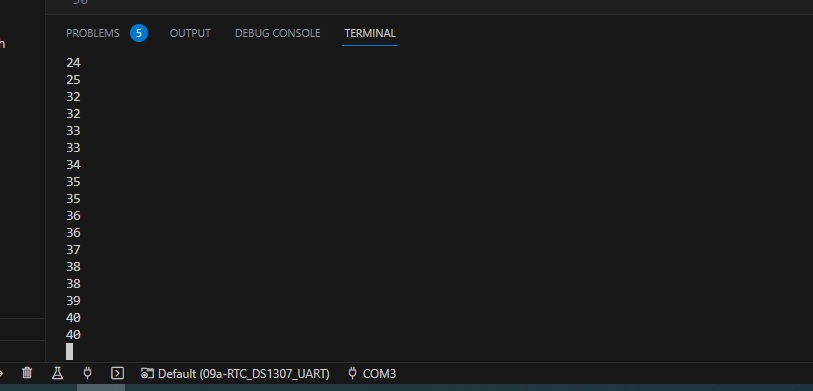
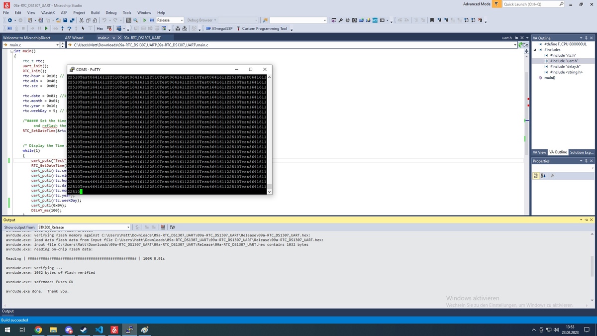
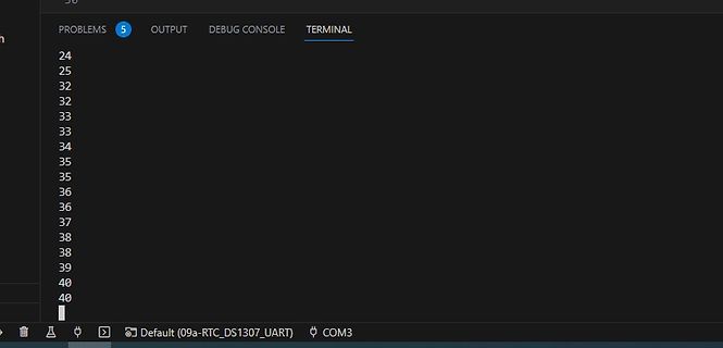
Screenshot eines Terminals mit Zahlenreihe
OUTPUT DEBUG CONSOLE TERMINAL 24 25 32 32 33 33 34 35 35 36 36 37 38 38 39 40 40 Default (09a-RTC_DS1307_UART) COM3
in „Atmega328p und DS1307“ · Mikrocontroller und Digitale Elektronik · · Screenshots
-
Datei
DS1307.c
-------------------------------------- //Funktion zum Lesen der Uhrzeit aus der Real Time Clock (DS 1307). void read_time(void) { uart_puts(" Read time start "); uint8_t i; //Zählvariable uint8_t buf[10]; i2c_start(0xD1); // Leseadresse des Bausteins senden //i2c_write(0x00); <<wird nicht unbedingt benötigt
in „Schon wieder DS 1307“ · Mikrocontroller und Digitale Elektronik ·
-
Datei
DS1307.asm
i2c_write ldi accu,0x10 rcall i2c_write rcall i2c_stop ret RTC_read: ldi yl,low(RTC_copy) ;Rohdaten des DS1307 ldi yh,high(RTC_copy) ; -"- rcall i2c_start ;Start ldi accu,0xD0 ;DS1307 Adresse rcall i2c_write ;schreiben clr accu ;h00 Wordadress als pointer rcall i2c_write ;schreiben rcall i2c_start ;restart
-
Datei
RTC.c
include "Main.h" #include "RTC.h" #include "TWI_Master.h" void RTC_read(){ // Starte Verbindung zu DS1307, schreibend TWI_Start(0b01101000, TWI_WRITE); TWI_Write(0x00); // Setze das Anfangsregister // in Lesemodus springen und auslesen TWI_Start_Rep(0b01101000, TWI_READ); for(int i=0;i<7;i++){ rtc_data
in „[C] GCC Atmega32, Menü über Funktionspointer, PeDa Entprellung, unterscheidet key_short/long nicht“ · Mikrocontroller und Digitale Elektronik ·
-
Datei
AT24C32.asm
------------------------------ EEPROM_write: rcall i2c_start ;i²C starten ldi accu,0xA0 ;Adresse DS1307 "W" rcall i2c_write ;schreiben mov accu,EE_Adr ;"Page" Adresse laden rcall i2c_write ;schreiben mov accu,EE_index ;Adresse unteres Byte rcall i2c_write ;schreiben lds accu,EE_copy+0 ;EE_copy schreiben
-
Datei
ds3231.c
= 1) { uputs(PSTR("RTC start1 failed..")); i2c_stop(); return 1; } errorStatus = i2c_sendAddress(DS1307_W); if(errorStatus == 1) { uputs(PSTR("RTC sendAddress1 failed..")); i2c_stop(); return 1; } i2c_receiveData_ACK(); errorStatus = i2c_sendData(0x00); if(errorStatus == 1) { uputs(PSTR("RTC write-2
in „i2c send data“ · Mikrocontroller und Digitale Elektronik ·
-
Datei
TWI_DS1307_routines.asm
andi temp1, 0xF8 lds temp1, TWDR ret ;_______________________________________________________ TWI_DS1307_set_adress: ;Setzt die RAM-Adresse push temp2 rcall TWI_init mov temp2, temp1 ldi temp1, 0b11010000 ;Slave address+Write rcall TWI_address_send mov temp1, temp2 ;Adress-Byte senden rcall TWI_byte_send
in „Probleme mit DS1307 und dessen Zeitausgabe“ · Mikrocontroller und Digitale Elektronik ·
-
Datei
configx.h
nothing() #define lcd_time_min() nothing() #else #if use_twi || use_twilcd || use_twi_rtc #define i2c_ds1307 1 #include "C:\zuc\i2c\twimaster.h" #include "C:\zuc\i2c\kk_twixx.h" #endif #if use_twilcd #define use_glcd 0 //#include "kk_alt_lcdxx.h" //C:\WinAVRkk\kklibx\// #include "C:\zuc\lcd\twilcd.h" //C:
in „Header Datei für Konfiguration erstellen“ · Mikrocontroller und Digitale Elektronik ·
-
Datei
Uhr_Temp.asm
/* * Uhr_Temp.asm * * Version: v1 * Verwendete Hardware: -ATMega128A -DS1307 -AT24C32 -DS18B20 -MAX232 -LCD 16x2 * Eine Uhr mit EntsorgungsKalender. * -Restmüll * -Papier * -Gelber Sack * * Einstellungen mit PC-Terminalprogramm * zu aktivieren mit der leertaste * * Created:
-
Datei
rtc.c
); if(errorStatus == RTC_ERROR) { i2c_stop(); return(RTC_ERROR); } errorStatus = i2c_sendAddress(DS1307_W); if(errorStatus == RTC_ERROR) { i2c_stop(); return(RTC_ERROR); } errorStatus = i2c_sendData(0x00); if(errorStatus == RTC_ERROR) { i2c_stop(); return(RTC_ERROR); } for(i=0;i<7;i++) { errorStatus
in „suche C source für die DS1307 RTC“ · Mikrocontroller und Digitale Elektronik ·
-
Datei
rtc.c
); if(errorStatus == RTC_ERROR) { i2c_stop(); return(RTC_ERROR); } errorStatus = i2c_sendAddress(DS1307_W); if(errorStatus == RTC_ERROR) { i2c_stop(); return(RTC_ERROR); } errorStatus = i2c_sendData(0x00); if(errorStatus == RTC_ERROR) { i2c_stop(); return(RTC_ERROR); } for(i=0;i<7;i++) { errorStatus
in „DS1307 Uhrzeit stellen über ein LCD“ · Mikrocontroller und Digitale Elektronik ·
-
Datei
UhrWS2812.ino
SoftwareWire.h> // must be included here so that Arduino library object file references work #include <RtcDS1307.h> #include <TimeLib.h> //http://www.arduino.cc/playground/Code/Time #include <Timezone.h> //https://github.com/JChristensen/Timezone #include <EEPROM.h> //Central European Time (Frankfurt, Paris)
in „LED Uhr mit RTC braucht Taster“ · Mikrocontroller und Digitale Elektronik ·
-
Datei
TWI.c
#include <stdlib.h> #include "types.h" #include "TWI.h" #include "usart.h" volatile adr; #define DS1307ADR 104 void TWI_SendByte (u08 Data) { TWCR = (1 << TWSTA) | (1 << TWEN) | (1 << TWINT); //Startbedingung while (!(TWCR & (1<<TWINT))); //Warten bis TWINT 1 if ((TWSR & TW_STATUS) != TW_START) //Check
in „Probleme mit DS1307 und Atmega 16“ · Mikrocontroller und Digitale Elektronik ·
-
Datei
main.c
Flankenwechsel 0 => ir_adr + CMD v u8 ir_tog; v u8 curpos=2,wdy=1,max,basis,next_step,step; v u8 displayZeile,ds1307menu=0; v u8 kkdat[11]; v u8 AbsFB=0; #include "FB_carmp3.c" #include "FB_RC5_64.c" #include "sub_irMenu.c" //================================================================================ //=====
in „Heizungssteuerung Wärmepumpe Fußbodenheizung“ · Mikrocontroller und Digitale Elektronik ·
-
Datei
main.c
lcd_int2(hou);lw(":"); lcd_int2(min);lw(":"); //init_ADC(); ds1820_init(); #if _I2C_kk_funktionen_h ds1307gefunden = i2c_start(0xd0); //0b11010000 - 188?? if (ds1307gefunden==0)kk_ds1307_getAll_to_global_struct_zt(); #endif lcd_clear(0); led1_off; bba_status=(1<<bba_status_kneten); DDRB|=(1<<4); PORTB&=
in „Brotbackautomat Steuerplatine defekt“ · Haus & Smart Home ·
-
Datei
RTC.C
")) : Serial.println(F(" DS1307 RTC ")); #endif break; default: DEBUG_PRINTLN(F("")); break; } nDevices++; } else if (error==4) { DEBUG_PRINT(F("Unknow error at address 0x")); if (address<16) DEBUG_PRINT(F("0")); DEBUG_PRINTLN_DEC_HEX
in „DS3231 RTCmit PC synchronisieren“ · Mikrocontroller und Digitale Elektronik ·
-
 Bild
Bild
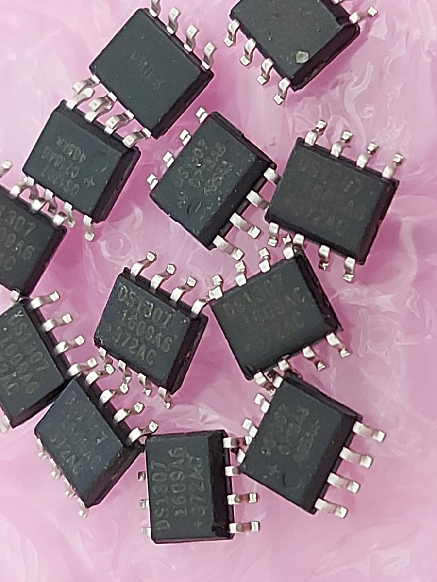
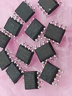
Mehrere integrierte Schaltkreise DS1307
DS1307 2609AG 372AC
in „[V] 12St. RTC Dallas DS1307 SO8 abzugeben (10€)“ · Markt · · Fotos
-
Datei
sub_irMenu.c
kkdat[5]*10+kkdat[6]; MON=kkdat[7]*10+kkdat[8]; YEA=kkdat[9]*10+kkdat[10]; //wdg20on; #if use_twi ds1307gefunden = i2c_start(0xd0); //0b11010000 - 188?? if (ds1307gefunden==0){ kk_ds1307_setAll();lcd_write(" ok....");}else{lcd_write("err1307");} #endif ir_cmd=10; //wdg20off; //no break case(10):ir_cmd
in „RC5 code einer IR Fernbedienung auslesen“ · Mikrocontroller und Digitale Elektronik ·
-
 Bild
Bild
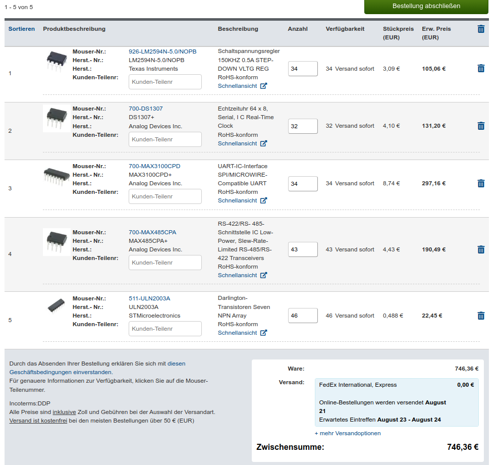
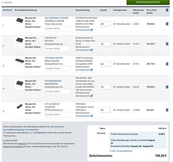
Warenkorb eines Elektronik-Online-Shops
Mouser-Nr.: 926-LM2594N-5.0/NOPB, LM2594N-5.0/NOPB, Texas Instruments, 700-DS1307, DS1307, Analog Devices Inc., 700-MAX3100CPD, MAX3100CPD, Analog Devices Inc., 700-MAX485CPA, MAX485CPA+, Analog Devices Inc., 511-ULN2003A, ULN2003A, STMicroelectronics, Zwischensumme: 746,36 €
in „[V] 34x LM2594N-5.0, 32x DS1307, 34x MAX3100, 43x MAX485, 46x ULN2003A“ · Markt · · Screenshots
-
Datei
rtc.h
RTC_ROUTINES HEADER FILE ******** // ************************************************************** #define DS1307_W 0xd0 #define DS1307_R 0xd1 #define RTC_NO_ERROR 0 #define RTC_ERROR 1 typedef struct { unsigned char time[9]; unsigned char date[12]; unsigned char day; unsigned char rtc_register[7]; } RTC_DATE_TIME
in „suche C source für die DS1307 RTC“ · Mikrocontroller und Digitale Elektronik ·
-
Datei
rtc.h
RTC_ROUTINES HEADER FILE ******** // ************************************************************** #define DS1307_W 0xd0 #define DS1307_R 0xd1 #define RTC_NO_ERROR 0 #define RTC_ERROR 1 typedef struct { unsigned char time[9]; unsigned char date[12]; unsigned char day; unsigned char rtc_register[7]; } RTC_DATE_TIME
in „DS1307 Uhrzeit stellen über ein LCD“ · Mikrocontroller und Digitale Elektronik ·
-
Datei
i2cnew.h
MR_DATA_ACK 0x50 #define MR_DATA_NACK 0x58 #define ARB_LOST 0x38 #define ERROR_CODE 0x7e #define DS1307_W ((0x68 << 1) | 0x01) #define DS1307_R ((0x68 << 1) & 0xFE) //#define EEPROM_W 0xa0 //#define EEPROM_R 0xa1 void twi_init(void); unsigned char i2c_start(void); unsigned char i2c_repeatStart(void);
in „i2c send data“ · Mikrocontroller und Digitale Elektronik ·
-
Datei
MENUE_Interrupt-Abfrage_Anzeige_Deklarierung.bas
Echtzeituhr Ddrd = &HFE Ddrb.1 = 1 Config Sda = Portc.1 ' I2C Bus konfigurieren Config Scl = Portc.0 Const Ds1307w = &HD0 ' Addresse der Ds1307 Uhr Const Ds1307r = &HD1 Config Clock = User '' Interne Time/Date Routinen für Bascom konfigurieren Config Date = Dmy , Separator = . ' *********** Konfiguration Ende
in „RXC Interrupt Problem ( Bascom)“ · Mikrocontroller und Digitale Elektronik ·
-
PDF
SCHALTUNG_DS1307_RTC.pdf
DS1307 RTC ) 7805 V IC2 +5V 1 0 10µ 10µ t LCD 2x16 Anmerkung: Diese LEDs könnten ev. Probleme bereiten r D n S / 0 1 2 3 4 5 6 7 16 V V K R R E D D D D D D D D k k 4 4 SDA Programmieradapter 1 5 1s SCL 2
in „DS1307 TWI I2C RTC Initialisierung ROM Zeit setzen auslesen Assembler ATmega8“ · Projekte & Code ·
-
PDF
SCHALTUNG_TV_DCF77_DS1307_RTC_ATmega1284P.pdf
TV - DCF77 DS1307 RTC - ATmega1284P t l t s g t c i n c o g n n t a i u n l R h E g O I k k 7805 R K C C C 1 1 Bei Bedarf +12V E T O D D D GND 1N4001 10µ 10µ Sekundentakt 450 R1 40 39 38 37 36 35 34 33 32 30 29 28 27
in „DCF77 RTC DS1307 TV FBAS / BAS LS-7 LS-8 ATmega1284P Assembler“ · Projekte & Code ·
-
Datei
ABFRAGE_UND_ANZEIGE_UHR_AT32_26_02_2010.HTML
; </font></font></font><B><font color="#000080">Const</font></B><font color="#000000"> Ds1307w </font><font color="#FF0000">=</font><font color="#000000"> </font><font color="#FF0000">&</font><font color="#000000">HD0
in „Passwortabfrage in Bascom“ · Mikrocontroller und Digitale Elektronik ·
-
PDF
arduinoheader.pdf
D R D D I U I T T D D D T E C P P P O O C C C O L L S S R R L L L R XTAL 1 0 +5 XTA1 0 XTAL 2.54 DS1307 R1 R2 1 8 Vishay CVRisChWay1C20R6C4WK7102F0K64EKA70FKEA X1 Vcc 2 7 7 X2 3SQW S V-Bat 3 D SCL 6 GND VCC GND 4 SDA 5 BAT- + DS1307Z 74LVT245WM C4 1 0 C1 1 20 GND T/R Vcc +5 A N N K Kyocera / AVX 0603YC103JAZ2A
in „Radio Projekt mit Fehler, brauche Hilfe :(“ · Mikrocontroller und Digitale Elektronik ·
-
Datei
main.asm
=========================================== ; ATmega8 Maker-Clock-FM-Radio mit PLL & 7-Segment + DS1307 ; CPU: 4 MHz RC-Oszillator intern ; Ports: ; SDA = PC4, SCL = PC5 (I²C DS1307) ; PORTD: Display-ZIFA/B/C/D, LATCH, SEGI, LM_SIN, LM_SCK ; PORTB: Tasten, EEPROM-Adr ; ===============================
in „Probleme mit DS1307 und dessen Zeitausgabe“ · Mikrocontroller und Digitale Elektronik ·
-
Datei
arduino.txt
-----------------------------------------------------------*/ //Variable für Real Time Clock RTC_DS1307 rtc; //Sensor ID const char *sID = "1"; //Sensor Bestätigungs String const char *OK; //Sting für Kommandos char *CMD; //String für den Zeitstempel char *dateANDtime; //Batteriestatus char *battStat
in „Arduino Micro Programmieren“ · Mikrocontroller und Digitale Elektronik ·
-
PDF
DS1307_RTC_ADJ.jpg.pdf
▯▯▯▯▯▯▯▯▯ ▯▯ ▯▯▯▯ ▯▯▯▯▯▯▯▯▯▯▯▯▯▯▯▯▯▯▯▯▯▯▯▯▯ ▯▯▯▯▯ ▯▯▯▯▯▯ ▯ !" #▯$▯▯ %&’
in „DS1307 rennt“ · Mikrocontroller und Digitale Elektronik ·
-
PDF
PA100D.pdf
C C V V Q4 BC856ASMD 32,768 kHz Q3 3k3 C12 LED1_RT A 1 2 8 R9 A 7 100n 150 1 2 C R 4 X X V R13 6 DS1307 7 GND SCL SCL D SQW/OUT SQW/OUT BC856ASMD 5 G 3 SDA SDA VBAT 2 3k3 IC4 DS1307Z+ + 0 LED1_GN 4 1 R R10 G C 150 - R14 JP7 C13 Q6 1 BC856ASMD 2 GND 100n 3k3 3 B 4k7 LED2_RT 4 B R11 5 IC9 R7 GND 150 16
in „Schutzbeschaltung Analog-Eingänge / Durchsicht Schaltplan“ · Mikrocontroller und Digitale Elektronik ·
-
Datei
main.asm
=========================================== ; ATmega8 Maker-Clock-FM-Radio mit PLL & 7-Segment + DS1307 ; CPU: 4 MHz RC-Oszillator intern ; Ports: ; SDA = PC4, SCL = PC5 (I²C DS1307) ; PORTD: Display-ZIFA/B/C/D, LATCH, SEGI, LM_SIN, LM_SCK ; PORTB: Tasten, EEPROM-Adr ; ===============================
in „Probleme mit DS1307 und dessen Zeitausgabe“ · Mikrocontroller und Digitale Elektronik ·
-
PDF
84123_usb_i2c_handbuch_v1_7.pdf
: FB Taster 4: F7 Taster 5: EF Taster 6: DF Taster 7: BF Taster 8: 7F 4.5.2. Echtzeituhr mit dem DS1307 Bei dem DS1307 handelt es sich um einen Uhrenbaustein von der Firma Maxim. Dieser kann über den I²C- Bus gestellt werden und liefert dann Sekunde, Minute, Stunde, Monat, Wochentag und Jahr. Er berücksich
in „Hygrosens I2C Tmp Modul antwortet nicht“ · Mikrocontroller und Digitale Elektronik ·
-
 Bild
Bild
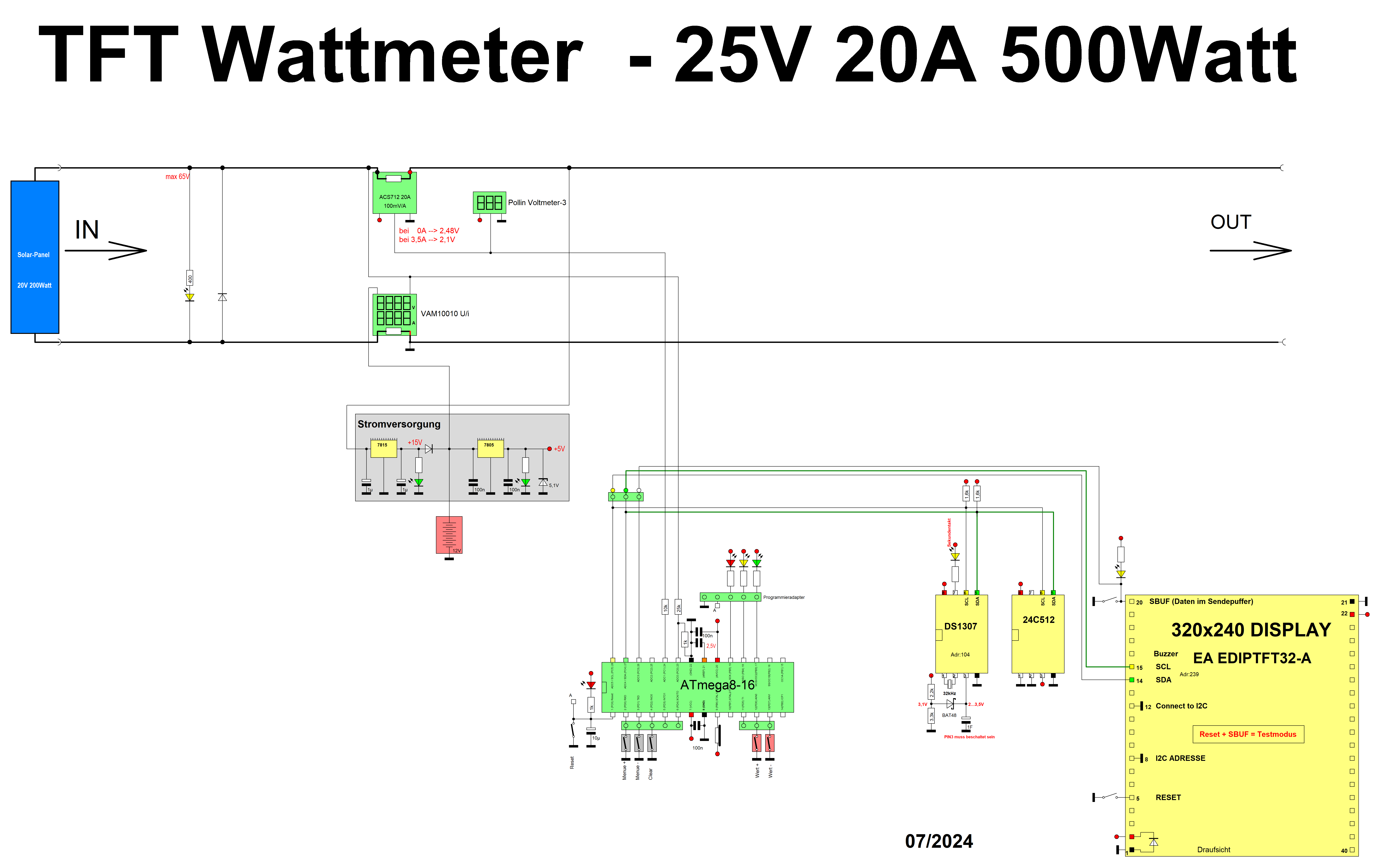
Schaltplan eines TFT-Wattmeters
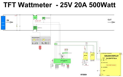
10A Polin Voltmeter-3 bei 5A -> 2.45V bei 3A -> 3.1V VAM10010 UI Stromversorgung 12V 5V ATmega8-16 DS1307 24C512 320x240 DISPLAY EA EDIPTFT32-A Buzzer SDA SCL Reset + SBUF + Testmodus DC ADRESSE RESET Draufsicht 07/2024
in „Wattmeter TFT EA_EDIPTFT32 24C512 DS1307 ACS712 graphisch Atmega8 Assembler“ · Projekte & Code · · Schaltpläne
-
 Bild
Bild
Screenshot einer Entwicklungsumgebung mit C-Code und Terminal
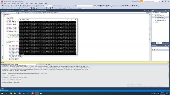
Ols_RTC_DS1307_UART . Microchip Studio File Edit View Valgrind ASF Project Debug Tools Window Help Advanced Mode Quick Launch (Ctrl+Q) main.c #include <uart.h> #include <delay.h> #include <string.h> void main() {
in „Atmega328p und DS1307“ · Mikrocontroller und Digitale Elektronik · · Screenshots
-
Datei
rtc.bas
b2 symbol day = b3 symbol date = b4 symbol month = b5 symbol year = b6 symbol control = b7 ; set DS1307 slave address i2cslave %11010000, i2cslow, i2cbyte ; Initialise the clock - "Thu 2003-12-25 11:59:00" let day = $03 ; 03 Note all BCD format let year = $03 ; 03 Note all BCD format let month = $12
in „DS1307 ungültige Sekundenanzahl“ · Mikrocontroller und Digitale Elektronik ·
-
Datei
sketch_nov21a.ino
include "RTClib.h" #include <SD.h> #include <SPI.h> #define pinCS 10 // Pin 10 auf Arduino Uno RTC_DS1307 rtc; File myFile; int temperatur = 20; DateTime now, last; TimeSpan ts; void setup() { // init UART Serial.begin(9600); while (!Serial); // init RTC if (!rtc.begin()) { Serial.println("Couldn't find
in „SD-KArte jede stunde einen Wert speichern“ · Mikrocontroller und Digitale Elektronik ·
-
Datei
Quellcode.txt
void main() { ds1307_init(); lcd_init(); strcpy(temp,"warte..."); lcd_put_string(temp); delay_ms(3000); port_b_pullups(TRUE); clear_interrupt(int_RB); help++; help--; set_tris_b (0xFF); enable_interrupts(GLOBAL); enable_interrupts
in „Seltsames µC Verhalten nach Unterbrechung von UB“ · Mikrocontroller und Digitale Elektronik ·