??_AT89LP3240_ NUMBER 000A ??_AT89LP4052_ NUMBER 0002 ??_AT89LP428_ NUMBER 0006 ??_AT89LP51ED2_ NUMBER 0011 ??_AT89LP51IC2_ NUMBER 000E ??_AT89LP51ID2_ NUMBER 0010 ??_AT89LP51RB2_ NUMBER 000C ??_AT89LP51RC2_ NUMBER 000D ??_AT89LP51RD2_ NUMBER 000F ??_AT89LP51_ NUMBER 0007 ??_AT89LP52_ NUMBER 0008 ??_AT89LP6440_ NUMBER 000B ??_AT89LP828_ NUMBER 0009 ??_AT89LS51_ NUMBER 0019 ??_AT89LS52_ NUMBER 001A ??_AT89S2051_ NUMBER 0012
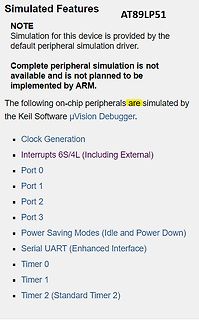
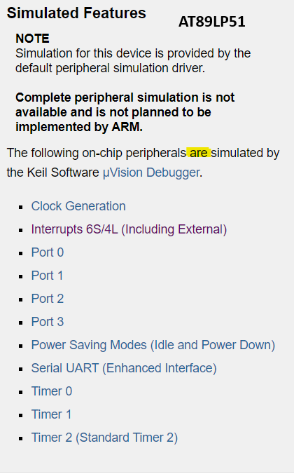
Simulated Features
AT89LP51
NOTE
Simulation for this device is provided by the default peripheral simulation driver.
Complete peripheral simulation is not available and is not planned to be implemented by ARM.
The following
uVision Debugger (5.38.00 Eval Version) kommt in der Simulation nicht mit PowerDown klar, wenn ich den AT89LP51RB2 als Device verwende. Diese simple Loop kann ich im Single Step (F11) durchgehen, obwohl beim PCON |= 2 die Simulation sofort anhalten sollte, weil die Clock steht. [code] int count = 0; void
Aussagen von Keil zu den beiden Chips. Daraufhin hatte ich angenommen, PD geht in der Simulation beim AT89LP51.
sowieso nicht möglich ist, werde ich auch nicht versuchen, da durchzusteigen. Habe mir jetzt den Atmel AT89LP51RB2 ausgesucht, ist bei Mouser verfügbar. Der wird ordentlich von Keil supportet und kann weit mehr, als ich benötige. Zumindest konnte ich schon erste Simulationen erfolgreich durchlaufen.
LinschringverhalteneiaBeschleunigen 64 t t t t 1,11- 1,999 -----~-_-_ - Anzeigeschritt 65 t t t t l=lp1 1=5ua ---_-- -_ vorerstohne Funktion 66 0 0 0 0 0eingeben ----_- -- -. VerweilzeitDrehrichtunqs-Uskehr 61 t t t t I <.<65,535[s] ArbeitsspindeflCrZyklus ‘Gerindebohren” ---- -------__ -- SpeicherfunktiofYr
JLCPCB-Bestellung habe ich noch 4 Leiterplatten übrig. Es handelt sich um einen Programmieradapter für die AT89S(LS/LP)-Mikrocontroller wie in https://www.mikrocontroller.net/topic/73988 beschrieben. Alle dort gegebenen Hinweise zu Ergänzungen sind eingearbeitet. Als Buffer-IC wird ein 74HCT541NS verwendet.
pin for tamper detection Note: It is always safe to set the BKP_CTRL.TP_ALEV and BKP_CTRL.TP_EN bits at the same time. However, clearing both at the same time produces a false tamper event. Therefore, it is recommended to change the state of the BKP_CTRL.TP_ALEV bit only when BKP_CTRL.TP_EN is 0. 5.4.4
protected EEPROM block beginning at selected address Read data from the protected EEPROM block beginning at the selected IDREAD 0011 0011 address CLRRAM 0101 0100 Clear all SRAM data to ‘0’ DS20002300E-page 10 2012-2023 Microchip Technology
LOOPBACK Near-end (Remote) loopback is conducted at PHY port 1 of the KSZ8851SNL. The loopback path starts at the PHY port’s receive inputs (RXP/RXM), wraps around at the same PHY port’s PMD/PMA, and ends at the PHY port’s transmit outputs (TXP/TXM).
leider Philips/NXP seine 8051 mit I2C vollständig abgekündigt. Eine Umrüstung auf Atmel ATmega8 und AT89LP51RD2 ist dann gründlich in die Hose gegangen, die sind definitiv nicht als Multimaster geeignet. Mit Haufen Timeouts, Retries ging eine Notlösung, allerdings mit unterirdischen Antwortzeiten. Wir
befüllt. Wir haben aber noch zusätzlich einen Message-FIFO im SRAM angelegt. Später haben wir den AT89C51CC03 und den AT90CAN128 verwendet. Der CAN-Controller ist bei allen 3 gleich aufgebaut, d.h. auch 15 MOBs. Zur Programmierung gibt es nicht viel zu sagen. Man setzt die Timingregister für die
selbst, vier LED-Displays mit gemeinsa- mer Kathode (TLR 324 von Toshiba) und einem Mikrocontroller AT89C2051 von Atmel(eswärenauchandereTypendenk- bar) istnur noch ein Temperatursensor er- forderlich. Der dafür gewählte LM75 von National Semiconductor passt sehr gut zum Rest der Elektronik, da er ebenfalls
Ob S. schrieb im Beitrag #7633828: > Die explizite Abkündigung ist inzwischen erfolgt für AT89xxxx, ATMEGA16x, ATMEGA32x, ATMEGA48x, ATMEGA644x, ATMEGA85x5L, ATMEGA88, ATMEGA8A, ATTINY13V, ATTINY24, ATTINY44, ATTINY461, ATTINY48, ATTINY84, ATTINY861 and ATTINY88 device families in PDIP.
klar das es einen 328PB Nachfolger gibt. Echte Ersatzlose Abkündigung kann ich nicht erkennen. AT89xxxx ...... ATMEGA16x ..... ATMEGA32x ..... ATMEGA328PB ATMEGA48x ..... ATMEGA644x .... ATMEGA85x5L ... ATMEGA88 ...... ATMEGA8A ...... ATTINY13V ..... ATTINY24 ...... ATTINY44 ..
Voltages – 2.7 - 5.5V Operating temperature – Industrial (-40°C to +85°C) Maximum Frequency – 8 MHz at 2.7V - Industrial range – 16 MHz at 4.5V - Industrial range 2 AT90USB82/162 7707F–AVR–11/10 AT90USB82/162 1. Pin Configurations Figure 1-1. Pinout AT90USB82/162 B . C ) / 1 T A N IN A K C C C C D S D
sein und nicht zum Keil vergleichbar otimiert. Dabei gibt es durchaus leistungsfähige 8051, z.B. AT89LP51RD2 (20 MIPS).
Peter D. schrieb im Beitrag #7603117: > Dabei gibt es durchaus leistungsfähige 8051, z.B. AT89LP51RD2 (20 MIPS). Lahme Gurke! ;-) https://www.silabs.com/mcu/8-bit-microcontrollers/c8051f12x-f13x
kleinen Streich erinnert, den wir vor einigen Jahren unseren Kollegen gespielt haben. Ein kleiner AT90USB162 wurde dazu mit der LUFA-Bibliothek von Dean Camera (Four Walled Cubicle) so programmiert, daß er sich beim Rechner als HID-Tastatur und -Maus angemeldet, und zufällig "eine Taste gedrückt" oder
"It's a UNIX system! I know this!" Siehe auch: https://www.reddit.com/r/MovieDetails/comments/89p4n4/in_jurassic_park_the_infamous_its_a_unix_system_i/ SCNR :)
1GB) X X Expandability Microtower Small Form Factor PCI slots 2 Full Length 5V 32 bit PCI slots 2 LP 5V 32 bit PCI slots Max power per slot 25W 25W PCIe x1 slot 1 1 Max power per slot 10W 10W PCIe X16 slot 1 Full Height card 1 LP profile card Max power per slot 75W 25W External Bays 3.5" 1 1 5.25" 2
1GB) X X Expandability Microtower Small Form Factor PCI slots 2 Full Length 5V 32 bit PCI slots 2 LP 5V 32 bit PCI slots Max power per slot 25W 25W PCIe x1 slot 1 1 Max power per slot 10W 10W PCIe X16 slot 1 Full Height card 1 LP profile card Max power per slot 75W 25W External Bays 3.5" 1 1 5.25" 2
and voltage: RMS value by analog computation method Active poner: tine-division multipLication timed at approx. 70 kHz Electrical energy: voltage Eo frequency conversion after time-division multiplicat ion Measuring period: 480 ms at 50 tlzmains frequency 400 ms at 60 Hz mains frequency RelaxaEion period
Hallo, Noch eine Konvolut 18 Stück gebrauchter 8051 PLCC44 ( Nicht eingelötet) und noch 3 neue AT89LP52-20MU 44VQFN 10€ + 2,50€ Versand (Versand DHL/Post und Paypal, notfalls Überweisung ) Bei Interesse bitte PM mit Artikelangabe. Danke! MFG Roger
thermal Output Noise Voltage (10 Hz to 100 kHz) (Note 11) V mVrms n CL= 1.0 mF − 126 − CL= 100 mF − 56 − LP2951A/LP2951AC Only Reference Voltage (T = 25°C) V V A ref LP2951C/LP2951C−XX/NCV2951C* 1.210 1.235 1.260 LP2951AC/LP2951AC−XX/NCV2951AC* 1.220 1.235 1.250 Reference Voltage AT = −40 to +125°C) V ref V LP2951C/LP2951C−XX/NCV2951C* 1.200 − 1.270 LP2951AC/LP2951AC−XX/NCV2951AC* 1.200 − 1.260 Reference Voltage AT = −40 to +125°C) V ref V O = 100 mA to 100 mA,in = 23 to 30 V LP2951C/LP2951C−XX/NCV2951C* 1.185
Controllers The Enhanced Host controllers share its ports with UHCI Host controllers in the ICH9. The UHC at D29:F0 shares ports 0 and 1; the UHC at D29:F1 shares ports 2 and 3; the UHC at D29:F2 shares ports 4 and 5 with the EHC at D29:F7, while the UHC at D26:F0 shares ports 6 and 7, the UHC at D26:F1 shares
Beitrag #7557116: > Michael schrieb: >> Ich war sehr froh als der 8051 rauskam > > Für mich war der 89C2051 der erste Mikrocontroller, an dem ich wirklich > Freude hatte. Davor fand ich den Eigenbau von Schaltungen mit > Mikrocontroller einfach nur anstrengend. Ja. Der uC ist die Mikroprozessor-LP
> NEIN, ihr dürft auch keinen ISP benutzen, denn der olle 8051 hatte das > auch nicht. Bei den AT89C51RC2 verwendete ich früher mal auch selbstverständlich den Serial ISP oder auch den ASIX ISP Daß mir 8-bitter immer noch wegen ihrer Gutmütigkeit und Einfachheit gefallen, sollte kein Verbrechen
Die Fläche des Standardquarzes beträgt ca. 50mm , die des LP-Quarzes ca. 16mm . 2 Die Frequenz eines AT-Schwingers hängt von der Dicke der Quarzscheibe ab, die Induktivität ist dagegen annähernd umgekehrt proportional zu deren Oberfläche. Da das Flächenverhältnis
Calibration Bits Note: By convention, the Configuration Word is The oscillator calibration bits are stored at the Reset stored at the logical address location of vector as the operand of a MOVLW instruction. Program- 0xFFF within the hex file generated for the ming interfaces must allow users to program the
at minimal battery voltage η 96.95% max,Vbatt,min Nominal efficiency at maximal battery voltage ηnom,Vbatt,max 92.64% Nominal efficiency at nominal battery voltage ηnom,Vbatt,nom 91.32% Nominal efficiency at
II tab, two additional markers are added. If measuring an antenna, the two markers could be placed at SWR=2 at the "low end" and at the "high end". Clicking the button Antenna Q, a new window appear and the antenna Q could be calculated. There are two different methods of calculating the Q. The first
of C1 and C2. • EC: External High-Speed Clock Input 2: A series resistor (RS) may be required for AT (PIC16F505 only) strip cut crystals. 7.2.2 CRYSTAL OSCILLATOR/CERAMIC 3: RF approx. value = 10 MΩ. RESONATORS In HS (PIC16F505), XT or LP modes, a crystal or FIGURE 7-2: EXTERNAL CLOCK INPUT ceramic
verschiedenes durchgemessen: - Aufladen funktioniert. Ladestrom i.O. (Ein Lüfter der auf der Haupt-LP angeschlossen wird, lief nicht. Andere Lüfter von der Lade-LP gesteuert schon). - Run-LED blinkt und RX/TX-LED leuchten auf Batterie-LP wenn der Power ON Knopf gedrückt wird. Gehen nach kurzer Zeit
station began charging. When the battery reaches 1 percent, the error is gone. Fans were repaired at this station. 2. At the second station, the connection with the battery periodically loses during charging (error E07). At the same time, the charge continues. After a while, the error disappeared
komplett anders als die von LCDs. Über die Jahre waren auch verschiedene Controller drauf, z.B. ein AT89C51. Neuere VFDs hatten das Problem, daß sie beim Schreibzugriff deutlich flackern. Wir haben dann Pausen eingefügt, damit das nicht so auffällt. Anbei mal ein Datenblatt.
LED is off (meaning CM ,Hsince the output is at high current to be shunted away from the LED (which is not state), if an imbalance between I and I results in a LP LN wanted when the LED should be on) or conversely causing transient F equal to or greater
LED is off (meaning CM ,Hsince the output is at high current to be shunted away from the LED (which is not state), if an imbalance between I and I results in a LP LN wanted when the LED should be on) or conversely causing transient F equal to or greater
jetzt ein Fahrradhändler residiert. Andererseits habe ich in dem Lokal vor Jahrzehnten von Aldi eine LP erworben, Claptons "Slowhand", damals aktuell ...
#7515923: > Beachte die gesprengte Kette in der neueren Version! Welche? https://www.kleinezeitung.at/politik/innenpolitik/5518124/Ohne-gesprengte-Ketten_Falsche-Aufregung-um-falschen-Bundesadler
Entscheidend ist für mich aber der Ruhestrom und der ist schwierig rauszulesen aus den verschiedenen LP2950 Datenblättern. Es sind vermutlich 75uA, was im Verhältnis zu den gebrauchten 10uA des uC im Sleepmode schon ein Vielfaches ist. Dann lese ich hier in einem anderen Beitrag, dass der LP2950 sowieso
HT75xx-1 ; HT7530-1 ; 3% ; Vin = 30 V ; Iq = 2,5 µA ; max. 100 mA ; TO92 ; SOT89 ; OT23-5 HT75xx-2 ; HT7530-2 ; 1% ; Vin = 30 V ; Iq = 2,5 µA ; max. 100 mA ; TO92 ; SOT89 ; OT23-5
Die Fläche des Standardquarzes beträgt ca. 50mm , die des LP-Quarzes ca. 16mm . 2 Die Frequenz eines AT-Schwingers hängt von der Dicke der Quarzscheibe ab, die Induktivität ist dagegen annähernd umgekehrt proportional zu deren Oberfläche. Da das Flächenverhältnis
den Kopierschutz 1990/91 aus meinem 57er ausgebaut. Erst mit einem Monoflop, spaeter dann mit einem AT89C2051 der die I2C MCU und DSP (DAT Signal Processor) befummelt. Waren ein paar harte Naechte mit einem HM103, aber wir Studenten waren ja arm und hatten nix. .-) Und ja MiniDisc war grosse kacke.
unabhängig von vermuteten oder tatsächlichen Klangunterschieden bleibt zwischen LP und CD der kulturelle Unterschied: Das vorsichtige Rausnehmen aus der LP-Hülle, nur am Rand anfassen, nicht drauftatschen, das vorsichtige Auflegen auf den Plattenteller und der spannende Moment wenn
not have to • PIC16F1847 • PIC16LF1847 be brought to a different voltage, but can instead be left at the normal operating voltage. 1.0 OVERVIEW 1.1.2.1 Single-Supply ICSP Programming The PIC16F/LF1847 and PIC12F/LF1840 devices can The LVP bit in Configuration Word 2 enables single- be programmed using
3.0V (Typ), Max. 104MHz Integrated Silicon Solution, Inc.- www.issi.com 80 Rev. L9 02/20/2022 IS25LP128 9.3 DC CHARACTERISTICS (Under operating range) Symbo (2) l Parameter Condition Min Typ Max Units NORD at 50MHz, 5 9 (3) FRD Single at 133MHz 7 11 ICC1 V CCActive Read current FRD Quad at 133MHz 10
turn on at each FEEDBACK PIN USED FOR IMPROVED oscillatorcycle,thenturnoffwhenswitchcurrentreaches LOOP TRANSIENT RESPONSE 1.24k OR SOFT START a trip level set by VC voltage. This trip level is zero at VC=0.9V,
Stefan H. schrieb im Beitrag #7472793: > Beim AT89LP51 würde das externe Mappen der oberen 32k bedeuten, dass ich > die Adressdecoder umstricken und entsprechend alle Zugriffe im Code > anpassen müsste, die Kröte würde ich wohl schlucken. Das
Peter D. schrieb im Beitrag #7472803: > Stefan H. schrieb im Beitrag #7472793: >> Beim AT89LP51 würde das externe Mappen der oberen 32k bedeuten, dass ich >> die Adressdecoder umstricken und entsprechend alle Zugriffe im Code >> anpassen müsste, die Kröte würde ich wohl schlucken. >
peinE CR.LP+BOl BLEi High order byte in the 2nd point LF DLI 1L ow order byte in the ist point EDI 0L2 LHigh order byte in the ist point CR.LP 0L3 «DL3N at t!e power ON (1oint data in 2 bytes) 6 - 4 1 O c t 2 0

 Bild
Bild
 Bild
Bild