-
Datei
uart.c
UART0_BIT_TXEN TXEN #define UART0_BIT_UCSZ0 UCSZ0 #define UART0_BIT_UCSZ1 UCSZ1 #elif defined(__AVR_ATmega48__) || defined(__AVR_ATmega48A__) || defined(__AVR_ATmega48P__) || defined(__AVR_ATmega48PA__) || defined(__AVR_ATmega48PB__) || \ defined(__AVR_ATmega88__) || defined(__AVR_ATmega88A__) || defined
in „Timerberechnung die hunderste“ · Mikrocontroller und Digitale Elektronik ·
-
Datei
uart.c
UART0_BIT_TXEN TXEN #define UART0_BIT_UCSZ0 UCSZ0 #define UART0_BIT_UCSZ1 UCSZ1 #elif defined(__AVR_ATmega48__) || defined(__AVR_ATmega48A__) || defined(__AVR_ATmega48P__) || defined(__AVR_ATmega48PA__) || defined(__AVR_ATmega48PB__) || \ defined(__AVR_ATmega88__) || defined(__AVR_ATmega88A__) || defined
in „Fehler beim kompilieren des Bootloadertoutorials in C“ · Mikrocontroller und Digitale Elektronik ·
-
Datei
uart.c
UART0_BIT_TXEN TXEN #define UART0_BIT_UCSZ0 UCSZ0 #define UART0_BIT_UCSZ1 UCSZ1 #elif defined(__AVR_ATmega48__) || defined(__AVR_ATmega48A__) || defined(__AVR_ATmega48P__) || defined(__AVR_ATmega48PA__) || defined(__AVR_ATmega48PB__) || \ defined(__AVR_ATmega88__) || defined(__AVR_ATmega88A__) || defined
in „Wie macht man solche Lichtmodes? Lauflicht, PWM und Co“ · Mikrocontroller und Digitale Elektronik ·
-
PDF
avrdude.pdf
STK600-SOIC ATtiny87 ATtiny167 STK600-RC028T-3 STK600-DIP ATtiny28 STK600-RC028M-6 STK600-DIP ATtiny48 ATtiny88 ATmega8 ATmega8A ATmega48 ATmega88 ATmega168 AT- mega48P ATmega48PA ATmega88P AT- mega88PA ATmega168P ATmega168PA ATmega328P QT600-ATTINY88- ATtiny88 QT8 STK600-RC040M-4 STK600-DIP ATmega8515
in „AVRDude als Tool in AVR Studio 4 einbinden“ · Mikrocontroller und Digitale Elektronik ·
-
Datei
AVR8_Burn_O_Mat_Config.xml
caption="4.0V (3.7V - 4.5V)" Fuse1="0" Fuse2="0"/> </BrownOutDetection> <OscillatorOptions Type="ATmega8" /> </AVR> <AVR name="m48" caption="ATmega48"> <Fuse name="UNUSED_E7" bit="7" fuseByte="efuse" default="1" desc="unused" mode="expert"/> <Fuse name="UNUSED_E6" bit="6" fuseByte="efuse" default="1"
-
PDF
SermultiChip.pdf
1 Multimeter Multimeter Display Controller …. Atmega48 Display Software 7905 232 DCDC Conv. 5->9 Optische Trennung 232 Attiny45 USB Stack USB Buchse Mini Messgerät Nr2… Messgerät Nr3… USB Hub PC mit Auswertesoftware USB to 232 driver Konfiguration 2
in „Multimeter mit serieller Schnittstelle für unter 10€“ · Projekte & Code ·
-
Datei
AVR8_Burn_O_Mat_Config.xml
caption="4.0V (3.7V - 4.5V)" Fuse1="0" Fuse2="0"/> </BrownOutDetection> <OscillatorOptions Type="ATmega8" /> </AVR> <AVR name="m48" caption="ATmega48"> <Fuse name="UNUSED_E7" bit="7" fuseByte="efuse" default="1" desc="unused" mode="expert"/> <Fuse name="UNUSED_E6" bit="6" fuseByte="efuse" default="1"
in „Pollinboard Ponyprog. Probleme mit 644P“ · Mikrocontroller und Digitale Elektronik ·
-
PDF
AVRMicrocontrollers_Peripheral_Integration.pdf
ü ü ü ü 1 ü 1 6 (6) (6) (6) (6) (6) (6) ATmega48PB/88PB/168PB/328PB 32 4–32 0.5–2 1.8–5.5 20 10 8 ü ü ü 4 2/6 ü 2 1/3 ü ü ü ü 1/2 1/2 1/2 ü ü 6 ATmega80x/160x/320x/480x 28–48 8–48 1–6 1.8–5.5 20 10 16 ü ü ü 4 3 ü 5 ü ü ü ü ü ü 4 1 1 ü ü ü 3 ü ATmega64A/128A 64 64–128 4 2.7–5.5 16 10 8 ü ü ü 2 6 2 2 ü ü ü ü 2 1 1 ü 6 ATmega164PA/324PA/644PA/1284P 44 16–128 1–16 1.8–5.5 20 10 8 ü ü ü 4 2/2/4 ü 2 1/1/2 ü ü ü ü 2 1 1 ü 6 ü ATmega165PA/325PA/645P 44 16–64 1–4 1.8–5.5 16 10 8 ü ü 4 6 ü 2 3 ü ü ü ü 3 2 2 6 ü ATmega169PA/329PA
in „Nachfolger von Atmega169“ · Mikrocontroller und Digitale Elektronik ·
-
Datei
RTC.c
//Now Read and format time uint8_t data; while(1) { DS1307Read(0x00,&data); Time[8]='\0'; Time[7]=48+(data & 0b00001111); Time[6]=48+((data & 0b01110000)>>4); Time[5]=':'; DS1307Read(0x01,&data); Time[4]=48+(data & 0b00001111); Time[3]=48+((data & 0b01110000)>>4); Time[2]=':'; DS1307Read(0x02,&data); Time[1]=48+(data & 0b00001111); Time[0]=48+((data & 0b00010000)>>4); LCDClear(); LCDWriteString("DS1307 RTC Exmple"); LCDWriteStringXY(2,1,Time); //AM/PM if(data & 0b00100000) { LCDWriteStringXY(11,1,"PM"); } else
in „LCD zeigt nur die hälfte an“ · Mikrocontroller und Digitale Elektronik ·
-
PDF
techb_myavr_board_usb_kurz.pdf
controllers for the vorgesehenen Controller gehören zur Reihe der Mega-AVRs board belong to the MEGA-AVRs (ATmega8/48/88/168). The (ATmega8/48/88/168) und verfügen über alle wesentlichen system is designed after didactic principles for educational use Baugruppen. Das System ist nach didaktischen Gesichts- and
in „DS18S20, Atmega8, AVR Studio“ · Mikrocontroller und Digitale Elektronik ·
-
PDF
avr8-gnu-toolchain-3.4.0.663-readme.pdf
attiny261a attiny461a attiny861 attiny861a attiny43u attiny87 attiny88 at86rf401 at43usb355 at76c711 atmega103 at90usb82 at90usb162 atmega8u2 atmega16u2 atmega32u2 attiny1634 atmega8 atmega8a atmega48 atmega48a atmega48pa atmega88 atmega88a atmega88p atmega88pa atmega8515 atmega8hva at90pwm1 at90pwm2 at90pwm2b
in „ATtiny10 ISR TIM0_COMPB_vect“ · Mikrocontroller und Digitale Elektronik ·
-
Datei
uart_printf.c
Schnittstelle und redu- ziertem PRINTF fuer AVR-MCU. Protokoll 8N1 Controller mit Hardware-UART - ATmega8 - ATmega8515 - ATmega48 - ATmega328 - ATtiny2313, ATtiny4313 Controller mit USI-Serial - ATtiny24 - ATtiny84 - ATtiny25 - ATtiny85 Anschlussbelegungen: MCU PORT Funk.1 Funk.2 ---------------------
in „Ausgabe mittels printf über UART für ATmega / ATtiny“ · Projekte & Code ·
-
Datei
sd-reader_20090330_mega328.patch
146) @@ -74,16 +74,19 @@ /* defines for customisation of sd/mmc port access */ #if defined(__AVR_ATmega8__) || \ defined(__AVR_ATmega48__) || \ + defined(__AVR_ATmega48P__) || \ defined(__AVR_ATmega88__) || \ + defined(__AVR_ATmega88P__) || \ defined(__AVR_ATmega168__) || \ - defined(__AVR_ATmega328_
-
Datei
AVR8_Burn_O_Mat_Config.xml
caption="4.0V (3.7V - 4.5V)" Fuse1="0" Fuse2="0"/> </BrownOutDetection> <OscillatorOptions Type="ATmega8" /> </AVR> <AVR name="m48" caption="ATmega48"> <Fuse name="UNUSED_E7" bit="7" fuseByte="efuse" default="1" desc="unused" mode="expert"/> <Fuse name="UNUSED_E6" bit="6" fuseByte="efuse" default="1"
-
Datei
AVR8_Burn_O_Mat_Config.xml
caption="4.0V (3.7V - 4.5V)" Fuse1="0" Fuse2="0"/> </BrownOutDetection> <OscillatorOptions Type="ATmega8" /> </AVR> <AVR name="m48" caption="ATmega48"> <Fuse name="UNUSED_E7" bit="7" fuseByte="efuse" default="1" desc="unused" mode="expert"/> <Fuse name="UNUSED_E6" bit="6" fuseByte="efuse" default="1"
-
Datei
Bootloader.c
0x200 #endif #if ((defined __AVR_ATmega328__) | (defined __AVR_ATmega328P__)) #define UsartA UCSR0A #define UsartB UCSR0B #define UsartC UCSR0C #define UsartRXC RXC0 #define UsartTXC TXC0 #define UsartBaud UBRR0L #define UsartData UDR0 #
in „GCC Optimierung, unterschiedliche Codelänge“ · Mikrocontroller und Digitale Elektronik ·
-
PDF
NokiaLCD_c.pdf
...udio\7.0\Atmega 16 tea5767\Atmega 16 tea5767\NokiaLCD.c 1 / *-------------------------------------------------------------------------------- ------------------ Name : NokiaLCD.c Description : This is a driver for
in „PORT B LCD Atmega“ · Mikrocontroller und Digitale Elektronik ·
-
Datei
config.xml
caption="4.0V (3.7V - 4.5V)" BODEN="0" BODLEVEL="0"/> </BrownOutDetection> <OscillatorOptions Type="ATmega8"/> </AVR> <AVR name="m48" caption="ATmega48"> <Fuse name="UNUSED_E7" bit="7" fuseByte="efuse" default="1" desc="unused" mode="expert"/> <Fuse name="UNUSED_E6" bit="6" fuseByte="efuse" default="1"
in „Fuseeditor, grafische Benutzeroberfläche für AVRdude“ · Projekte & Code ·
-
Datei
AVR8_Burn_O_Mat_Config.xml
caption="4.0V (3.7V - 4.5V)" Fuse1="0" Fuse2="0"/> </BrownOutDetection> <OscillatorOptions Type="ATmega8" /> </AVR> <AVR name="m48" caption="ATmega48"> <Fuse name="UNUSED_E7" bit="7" fuseByte="efuse" default="1" desc="unused" mode="expert"/> <Fuse name="UNUSED_E6" bit="6" fuseByte="efuse" default="1"
-
Datei
tiny.txt
Low-Speicherstelle des Servos Nr. x (für x=1 bis 6) nach: Ramstart+2*(x-1) ; Schaltung : SPI: MOSI, SCK - ATMega8 zu ATTinys lt. Datenblatt (ohne MISO) ; ATMega8 - ATTiny2313 ; C1 - B0 ; C2 - B0 ; C3 - B1 ; ATtiny2313 auf Steckboard verbunden mit ATMega8 auf MYAVR-Board ; verbunden über SPI, ATMega als Master
in „SPI Kopplung von ATmega8 und ATtiny 2313“ · Projekte & Code ·
-
PDF
SpeedGrades.pdf
between 1.8V < V < 2.7V and between 2.7V < V < CC CC CC 4.5V. Figure 28-1. Maximum Frequency vs. V CC, ATmega48V/88V/168V 10 MHz Safe Operating Area 4 MHz 1.8V 2.7V 5.5V Figure 28-2. Maximum Frequency vs. V , ATmega48/88/168 CC 20 MHz 10 MHz Safe Operating Area 2.7V 4.5V 5.5V 306 ATmega48/88/168 2545M–AVR–
in „CP/M auf ATmega88“ · Mikrocontroller und Digitale Elektronik ·
-
Datei
atmel_beispiel.txt
Hope microelectronic Co.,Ltd. ;Author: Tank ;Current version: v1.0 ;Date: 2006-11-13 ;processor ATMEGA48 ;Clock: 10MHz Crystal ;Contact: +86-0755-86106557 ;E-MAIL: hopefsk@hoperf.com Connections ATMEGA48 SIDE RF12 SIDE SCK--------------->SCK MISO--------------->SDO MOSI--------------->SDI SS--------
in „RFM12 - Funkmodul“ · Mikrocontroller und Digitale Elektronik ·
-
PDF
8-bit-MCU-Overview.pdf
2 1.8–5.5 20 10 12 8 2 1 1 1 1 1 3 ATtiny42x ATmega48PB/88PB/168PB 32 4–32 0.5–2 1.8–5.5 20 10 8 4 2/65) 2 1/3(5) 1/2(5) 1/2(1/2(5) (3) 6 /328PB ATmega80x/160x/320x /480x 28–48 8–48 1–6 1.8–5.5 20 10 16 4
in „Moderne AVR (Nachfolger Atmega und Attiny)“ · Mikrocontroller und Digitale Elektronik ·
-
PDF
8-bit-MCU-Overview.pdf
2 1.8–5.5 20 10 12 8 2 1 1 1 1 1 3 ATtiny42x ATmega48PB/88PB/168PB 32 4–32 0.5–2 1.8–5.5 20 10 8 4 2/65) 2 1/3(5) 1/2(5) 1/2(1/2(5) (3) 6 /328PB ATmega80x/160x/320x /480x 28–48 8–48 1–6 1.8–5.5 20 10 16 4
in „AVR®DD family, low pin count devices“ · Mikrocontroller und Digitale Elektronik ·
-
PDF
8-bit-MCU-Overview.pdf
2 1.8–5.5 20 10 12 8 2 1 1 1 1 1 3 ATtiny42x ATmega48PB/88PB/168PB 32 4–32 0.5–2 1.8–5.5 20 10 8 4 2/65) 2 1/3(5) 1/2(5) 1/2(1/2(5) (3) 6 /328PB ATmega80x/160x/320x /480x 28–48 8–48 1–6 1.8–5.5 20 10 16 4
in „AVR®DD family, low pin count devices“ · Mikrocontroller und Digitale Elektronik ·
-
Datei
Example1_DisplayTest.ino
, 48); myTOLED.pixelSet(20, 48); myTOLED.pixelSet(21, 48); myTOLED.pixelSet(22, 48); myTOLED.pixelSet(23, 48); myTOLED.pixelSet(24, 48); myTOLED.pixelSet(25, 48); myTOLED.pixelSet(26, 48); myTOLED.pixelSet
in „Arduino OLED Display Ansteuern & "Hello World" Programme gehen nicht.“ · Softwareentwicklung ·
-
Datei
V1.5_Slave_6.12..txt
Low-Speicherstelle des Servos Nr. x (für x=1 bis 6) nach: Ramstart+2*(x-1) ; Schaltung : SPI: MOSI, SCK - ATMega8 zu ATTinys lt. Datenblatt (ohne MISO) ; ATMega8 - ATTiny2313 ; C1 - B0 (Slave 1) ; C2 - B0 (Slave 2) ; C3 - B1 ; ATtiny2313 auf Steckboard verbunden mit ATMega8 auf MYAVR-Board ; verbunden über SPI
in „SPI Kopplung von ATmega8 und ATtiny 2313“ · Projekte & Code ·
-
Datei
benchmark.c
copy 256 single bytes // PIC18@10MIPS = // PIC24@40MIPS = 96.20µs // dsPIC@30MIPS = 188.10µs // ATMEGA@16MIPS = 914µs // LPC2103@60MIPS = 64.02s pa8 = a; pb8 = b; for (i=0; i<256; i++) { *pa8++=*pb8++; } // clear 128 16bit words // PIC18@10MIPS = // PIC24@40MIPS = 48.20µs // dsPIC@30MIPS = 64.26µs // ATMEGA@16MIPS = 329µs // LPC2103@60MIPS = 23.47µs pa16 = (short*)a; for (i=0; i<128; i++) { *pa16++=0; } // fill 128 16bit words // PIC18@10MIPS = // PIC24@40MIPS = 48.20µs // dsPIC@30MIPS = 64.26µs // ATMEGA
in „LPC2103 63MIPS?“ · Mikrocontroller und Digitale Elektronik ·
-
Datei
spminterface.h
b6 fc sbrc r11, 6 1842: f4 cf rjmp .-24 ; 0x182c <waitA> 1844: 08 95 ret */ #elif defined (__AVR_ATmega48__) || defined (__AVR_ATmega48P__) || defined (__AVR_ATmega88__) || defined (__AVR_ATmega88P__) || defined (__AVR_ATmega168__) || defined (__AVR_ATmega168P__) #if defined (__AVR_ATmega88__) || defined
in „[ATMega] Programm aus externem EEprom laden“ · Mikrocontroller und Digitale Elektronik ·
-
Datei
verbosemode_nonull.txt
[ 0C 48 00 02 ] bitbang_cmd(): [ 40 00 03 E7 ] [ 94 40 00 03 ] bitbang_cmd(): [ 48 00 03 04 ] [ E7 48 00 03 ] bitbang_cmd(): [ 40 00 04 0C ] [ 04 40 00 04 ] bitbang_cmd(): [ 48 00 04 94 ] [ 0C 48 00 04 ] bitbang_cmd
in „Atmega2561 Programmieren mit AVRDude“ · Mikrocontroller und Digitale Elektronik ·
-
Datei
irsnd.c
Supported AVR mikrocontrollers: * * ATtiny87, ATtiny167 * ATtiny45, ATtiny85 * ATtiny44 ATtiny84 * ATmega8, ATmega16, ATmega32 * ATmega162 * ATmega164, ATmega324, ATmega644, ATmega644P, ATmega1284, ATmega1284P * ATmega88, ATmega88P, ATmega168, ATmega168P, ATmega328P * * $Id: irsnd.c,v 1.85 2015/04/23 12
in „IRMP - Infrared Multi Protocol Decoder“ · Projekte & Code ·
-
Datei
irsnd.c
Supported AVR mikrocontrollers: * * ATtiny87, ATtiny167 * ATtiny45, ATtiny85 * ATtiny44 ATtiny84 * ATmega8, ATmega16, ATmega32 * ATmega162 * ATmega164, ATmega324, ATmega644, ATmega644P, ATmega1284, ATmega1284P * ATmega88, ATmega88P, ATmega168, ATmega168P, ATmega328P * * $Id: irsnd.c,v 1.86 2015/05/07 06
in „IRMP - Infrared Multi Protocol Decoder“ · Projekte & Code ·
-
Datei
avr.h
=atmega48|\ mmcu=atmega88|\ mmcu=atmega64|\ mmcu=atmega644*|\ mmcu=atmega645|\ mmcu=atmega6450|\ mmcu=atmega649|\ mmcu=atmega6490|\ mmcu=atmega128|\ mmcu=atmega162|\ mmcu=atmega164*|\ mmcu=atmega165*|\ mmcu
in „ATtiny24 - ISR wird nie gerufen __vectors> fehlt“ · Mikrocontroller und Digitale Elektronik ·
-
Datei
uart_printf.h
reduziertem PRINTF fuer AVR-MCU. Protokoll 8N1 Unterstuetzte Controller: Controller mit Hardware-UART - ATmega8 - ATmega8515 - ATmega48 - ATmega328 - ATtiny2313, ATtiny4313 Controller mit USI-Serial - ATtiny24 - ATtiny84 - ATtiny25 - ATtiny85 Anschlussbelegungen: MCU PORT Funk.1 Funk.2 ---------------------
in „Ausgabe mittels printf über UART für ATmega / ATtiny“ · Projekte & Code ·
-
PDF
nRF24L01plus.pdf
2.4GHz-HowTo von der Beschreibung abweichend sind die folgenden Verbindungen: • nRF24L01+ CE → Arduino D8 (ATMega8 PB0) • nRF24L01+ CSN → Arduino D4 (ATMega8 PD4) • nRF24L01+ IRQ → Arduino D3 (ATMega8 PD3) Gaaaanz wichtig der 100µF Kondensator nahe bei der 3,3V Versorgung für den nRF24L01+ nicht vergessen. Die
in „Repeating und Routing Netzwerk mit Arduino und nRF24L01+“ · Projekte & Code ·
-
PDF
i2c.pdf
Adresse: 100 1000 + Write 1 #define MT_SLA_ACK 0x18 #define MR_SLA_ACK 0x40 #define MR_SLA_NACK 0x48 #define MT_DATA_ACK 0x28 #define MR_DATA_ACK 0x50 #define MR_DATA_NACK 0x58 #define BIT_RATE 0x50 #define POINTER_ADDRESS 0x00 #define SCL_CLOCK 10000UL uint8_t error1 = 0; #if defined (__AVR_ATmega32__) || (__AVR_ATmega328__) || defined (__AVR_ATmega328P__) || \ defined(__AVR_ATmega168P__) || defined(__AVR_ATmega168PA__) || \ defined(__AVR_ATmega88P__) || \ defined(__AVR_ATmega48P__) || \ defined(__AVR_ATmega1284P
in „Programm läuft nur mit JTAG Fuse“ · Mikrocontroller und Digitale Elektronik ·
-
Datei
AVRrescue.c
AT90S4414 {0x1E, 0x92, 0x03, 00, 00, 00}, // AT90S4433 {0x1E, 0x92, 0x05, 0x62, 0xDF, 0xFF}, // ATmega48 {0x1E, 0x92, 0x06, 0x62, 0xDF, 0xFF}, // ATtiny45 {0x1E, 0x92, 0x07, 0x62, 0xDF, 0xFF}, // ATtiny44 {0x1E, 0x92, 0x08, 0x62, 0xDF, 0xFF}, // ATtiny461 {0x1E, 0x92, 0x09, 0x62, 0xDF, 0xFF}, // ATtiny48
in „AVR-Rescue: standalone Parallel HV-Programmer“ · Projekte & Code ·
-
Datei
benchmark.c
= 188.10µs // ATMEGA@16MIPS = 914µs // Z16F@20MIPS = 77.0µs // LPC2103@60MIPS = 64.0µs pa8 = a; pb8 = b; for (i=0; i<256; i++) { *pa8++=*pb8++; } // clear 128 16bit words // PIC18@10MIPS = // PIC24@40MIPS = 48.20µs // dsPIC@30MIPS = 64.26µs // ATMEGA@16MIPS = 329µs // Z16F@20MIPS = 39.0µs // LPC2103@60MIPS = 23.47µs pa16 = (short*)a; for (i=0; i<128; i++) { *pa16++=0; } // fill 128 16bit words // PIC18@10MIPS = // PIC24@40MIPS = 48.20µs // dsPIC
in „LPC2103 63MIPS?“ · Mikrocontroller und Digitale Elektronik ·
-
 Bild
Bild
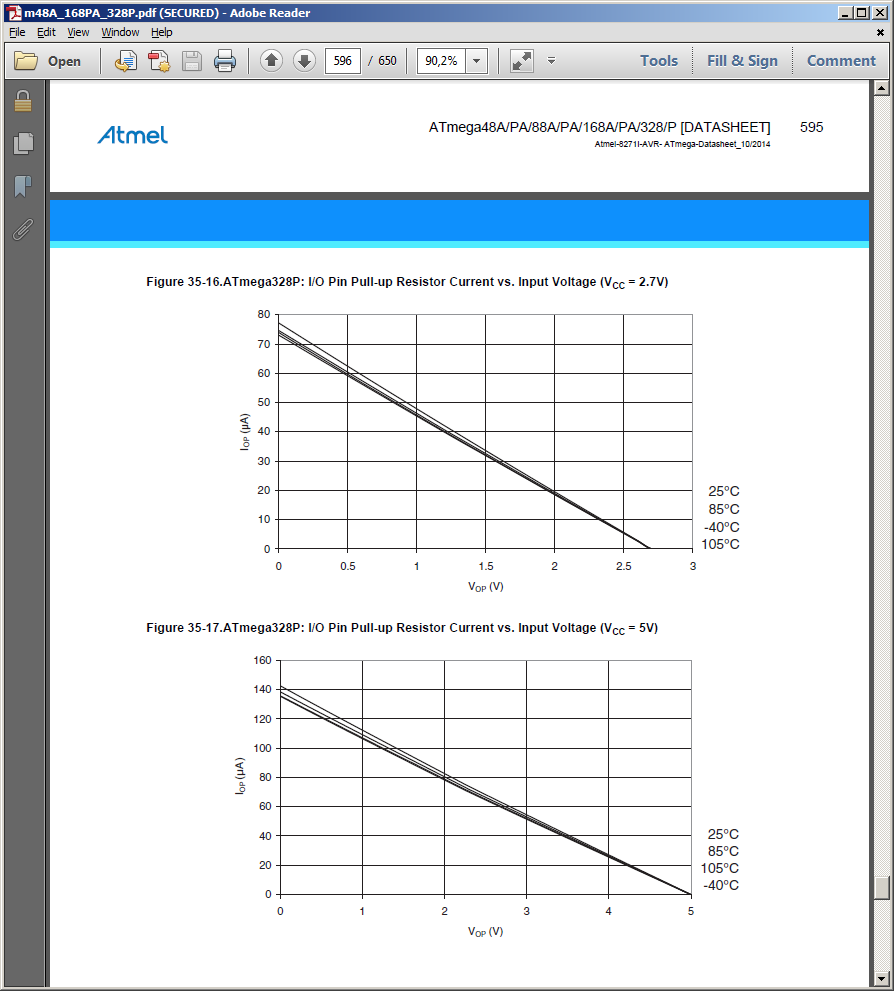
Datenblatt Diagramme für ATmega328P Pull-up Widerstand Strom
m48A_168PA_328P.pdf (SECURED) - Adobe Reader Atmel ATmega48A/PA/88A/PA/168A/PA/328P [DATASHEET] 595 Atmel-82711-AVR-ATmega-Datasheet_10/2014 Figure 35-16. ATmega328P: I/O Pin Pull-up Resistor Current vs.
in „ATmega328P Stromverbrauch“ · Mikrocontroller und Digitale Elektronik · · Screenshots
-
PDF
nRF24L01_.pdf
2.4GHz-HowTo von der Beschreibung abweichend sind die folgenden Verbindungen: • nRF24L01+ CE → Arduino D8 (ATMega8 PB0) • nRF24L01+ CSN → Arduino D4 (ATMega8 PD4) • nRF24L01+ IRQ → Arduino D3 (ATMega8 PD3) Gaaaanz wichtig der 100µF Kondensator nahe bei der 3,3V Versorgung für den nRF24L01+ nicht vergessen. Die
in „Repeating und Routing Netzwerk mit Arduino und nRF24L01+“ · Projekte & Code ·
-
Datei
benchmark.c
PIC24@40MIPS = 48.20µs // dsPIC@30MIPS = 64.26µs // ATMEGA@16MIPS = 329µs // Z8Enc!XP@20MIPS = 315.5µs // Z16F@20MIPS = 39.0µs // LPC2103@60MIPS = 23.47µs pa16 = (short*)a; for (i=0; i<128; i++) { *pa16++=0; } // fill 128 16bit words // PIC18@10MIPS = // PIC24@40MIPS = 48.20µs // dsPIC@30MIPS = 64.26µs // ATMEGA@16MIPS = 345µs // Z8Enc!XP@20MIPS = 314.5µs // Z16F@20MIPS = 38.0µs // LPC2103@60MIPS = 27.73µs pa16 = (short*)a; for (i=0; i<128; i++) { *pa16++=0x2211; } //
in „LPC2103 63MIPS?“ · Mikrocontroller und Digitale Elektronik ·
-
Datei
benchmark.c
// PIC24@40MIPS = 48.20µs // dsPIC@30MIPS = 64.26µs // ATMEGA@20MIPS = 231.4µs // Z8Enc!XP@20MIPS = 315.5µs // Z16F@20MIPS = 39.0µs // LPC2103@60MIPS = 23.47µs pa16 = (short*)a; for (i=0; i<128; i++) { *pa16++=0; } // fill 128 16bit words // PIC18@10MIPS = // PIC24@40MIPS = 48.20µs // dsPIC@30MIPS = 64.26µs // ATMEGA@20MIPS = 244.2µs // Z8Enc!XP@20MIPS = 314.5µs // Z16F@20MIPS = 38.0µs // LPC2103@60MIPS = 27.73µs pa16 = (short*)a; for (i=0; i<128; i++) { *pa16++=0x2211; }
in „LPC2103 63MIPS?“ · Mikrocontroller und Digitale Elektronik ·
-
Datei
benchmark.c
PIC24@40MIPS = 48.20µs // dsPIC@30MIPS = 64.26µs // ATMEGA@16MIPS = 329µs // Z8Enc!XP@20MIPS = 315.5µs // Z16F@20MIPS = 39.0µs // LPC2103@60MIPS = 23.47µs pa16 = (short*)a; for (i=0; i<128; i++) { *pa16++=0; } // fill 128 16bit words // PIC18@10MIPS = // PIC24@40MIPS = 48.20µs // dsPIC@30MIPS = 64.26µs // ATMEGA@16MIPS = 345µs // Z8Enc!XP@20MIPS = 314.5µs // Z16F@20MIPS = 38.0µs // LPC2103@60MIPS = 27.73µs pa16 = (short*)a; for (i=0; i<128; i++) { *pa16++=0x2211; } //
in „ATMEL billiger und leistungsfähiger als PIC“ · Mikrocontroller und Digitale Elektronik ·
-
Datei
main.c
If not, see <http://www.gnu.org/licenses/>. // // //VERSION 1.1 1Wire Barometric Pressure Sensor ATMEGA48 #define F_CPU 20000000UL //#include "i2c.h" //#include "bmp085.h" #include <avr/io.h> #include <avr/interrupt.h> #include <util/delay.h> #include "adc.h" #define C_BOARD_POTI PA7 #ifdef __AVR_ATmega644
in „1-Wire Slave auf AVR“ · Mikrocontroller und Digitale Elektronik ·
-
Datei
DOG2_SPI.asm
endif ;---------------------------------------------------------------------------------------- ; ATMega 48/88/168 .if (m48_88_168 ==1)|(m8==1) spi_out: push r18 out SPDR,r18 ; Start transmission of data (r16) spi_out10: in r18, SPSR ; Wait for transmission complete sbrs r18, SPIF rjmp spi_out10 pop r18 ret .message "Target: ATMega8/48/88/168" .endif ;---------------------------------------------------------------------------------------- ; Software SPI .if soft_spi== 1 spi_out: push r16 push r18 ldi r16,8 spi_out10: cbi lcdato
in „ea dog-m162 anschließen“ · Mikrocontroller und Digitale Elektronik ·
-
Datei
DOG2_SPI.asm
endif ;---------------------------------------------------------------------------------------- ; ATMega 48/88/168 .if (m48_88_168 ==1)|(m8==1) spi_out: push r18 out SPDR,r18 ; Start transmission of data (r16) spi_out10: in r18, SPSR ; Wait for transmission complete sbrs r18, SPIF rjmp spi_out10 pop r18 ret .message "Target: ATMega8/48/88/168" .endif ;---------------------------------------------------------------------------------------- ; Software SPI .if soft_spi== 1 spi_out: push r16 push r18 ldi r16,8 spi_out10: cbi lcdato
in „Display DOG-M an SPI- ich bekomme es nicht hin“ · Mikrocontroller und Digitale Elektronik ·
-
Datei
mega8.txt
fünf Positionen (vorn-Mitte-hinten;oben-unten) mit Low und High-Byte ; Schaltung : SPI: MOSI, SCK ATMega8 zu ATTinys, ISP und LCD-shielt lt. Datenblatt B3,B4,B5 ; ATMega8 - ATTiny2313 ; C1 - B0 ; C2 - B0 ; C3 - B1 ; ATMega8 - LCD-shield ; C0 - A0 ADC für Joystick ; D2 - RST Taster zur Umschaltung auf
in „SPI Kopplung von ATmega8 und ATtiny 2313“ · Projekte & Code ·
-
Datei
frage.h
INT1_FALLING_EDGE 0x08 #define INT1_RISING_EDGE 0x09 #define TIMSK1 TIMSK #endif #if defined (__AVR_ATmega328p__) //funktioniert nicht, compilerfehler //#if defined (__atmega328p__) //Interrupt an dem das DCF77 Modul hängt hier INT0 #define RFM12BP_INT_ENABLE() EIMSK |= (1<<INT0); #define RFM12BP_INT1_ENABLE
in „defines bedingt compilieren für m328 bringt Compilerfehler“ · Mikrocontroller und Digitale Elektronik ·
-
PDF
BabyController_B328.pdf
Baby Orangutan B-328 Robot Controller - Bezug Robotikhardware.de ' PWM Register setzen ' see the ATmega48/168/328P datasheet for detailed register info ' configure for inverted PWM output on motor control pins Tccr0a = &HF3 Tccr2a = &HF3 ' use the system clock / 8 (2.5 MHz) as the timer clock Tccr0b
in „Baby Orangutan b-328“ · Mikrocontroller und Digitale Elektronik ·
-
PDF
447.pdf
dead-time on an AVR, we continue to look at only one phase voltage. One timer/counter module on e.g. the ATmega48 can be used to control one half-bridge like the one in Figure 3-1. The timer/counter modules in the ATmega48 can control two PWM output pins each. The timer/counter units have several PWM modes,
in „Synchron- / BLDC - Motor zum Laufen bringen“ · Mikrocontroller und Digitale Elektronik ·