-
Datei
yaap.ini
; supported devices [Devices] Dev1=AT90S1200 Dev2=ATtiny12 Dev3=ATtiny15 ;Dev4=ATtiny22 Dev5=AT90S2313 Dev6=AT90S2323 Dev7=AT90S2333 Dev8=AT90S2343 Dev9=AT90S4414 Dev10=AT90S4433 Dev11=AT90S4434 Dev12=AT90S8515 Dev13=AT90S8535 Dev14=ATmega103 Dev15=ATmega103
in „Mega16 Programmieren“ · Mikrocontroller und Digitale Elektronik ·
-
Datei
1wire.cpp
along with this program. If not, see <http://www.gnu.org/licenses/>. // // //VERSION 1.1 DS2423 for ATTINY2313 and ATTINY25 //FOR MAKE by hand /* avr-gcc -mmcu=[attiny25|attiny2313] -O2 -c ow_slave_DS2423.c avr-gcc.exe -mmcu=[attiny25|attiny2313] ow_slave_DS2423.o -o ow_slave_DS2423.elf avr-objcopy -O ihex
in „1-Wire Slave auf AVR“ · Mikrocontroller und Digitale Elektronik ·
-
Datei
uart_printf.h
Unterstuetzte Controller: Controller mit Hardware-UART - ATmega8 - ATmega8515 - ATmega48 - ATmega328 - ATtiny2313, ATtiny4313 Controller mit USI-Serial - ATtiny24 - ATtiny84 - ATtiny25 - ATtiny85 Anschlussbelegungen: MCU PORT Funk.1 Funk.2 --------------------------------------------------- ATtiny25 - ATtiny85 PB1 TxD Do (6) PB0 RxD Di (5) --------------------------------------------------- ATtiny24 - ATtiny84 PA5 TxD Do (8) PA6 RxD Di (7) --------------------------------------------------- ATtiny2313 / 4313 PD1 TxD (3) PD0 RxD (2) --------------------------------------------------- 28 pol.
in „Ausgabe mittels printf über UART für ATmega / ATtiny“ · Projekte & Code ·
-
Datei
TimerPrescalersSorted.txt
<Prescaler>1:8:32:64:128:256:1024</Prescaler> ATtiny167.xml:6539: <TIMER1> ATtiny22.xml:1039: <TIMER0> ATtiny22.xml:16: <CORE_VERSION>V1</CORE_VERSION> ATtiny2313.xml:16: <CORE_VERSION>V2</CORE_VERSION> ATtiny2313.xml:4692: <TIMER0> ATtiny2313.xml:4704
in „Timer Vorteiler Werte Definition“ · Mikrocontroller und Digitale Elektronik ·
-
Datei
pi.c
/* pi.c: Compute the first 1000 hexadecimal digits of pi on an AVR ATtiny2313 microcontroller. */ /* Language: C99 Compiler: avr-gcc 4.7 if you like to compile for AVR ATtiny2313, or any C99-compliant compiler if you like to run this pogram on a PC. Hardware: AVR ATtiny2313
in „ATtiny2313 berechnet π auf 4000 Stellen“ · Projekte & Code ·
-
 Bild
Bild
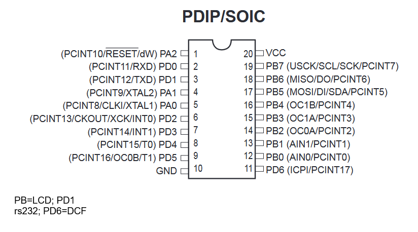
Pinbelegung PDIP/SOIC Mikrocontroller
PDIP/SOIC (PCINT10/RESET/dW) PA2 1 20 VCC (PCINT11/RXD) PD0 2 19 PB7 (USCK/SCL/SCK/PCINT7) (PCINT12/TXD) PD1 3 18 PB6 (MISO/DO/PCINT6) (PCINT9/XTAL2) PA1 4 17 PB5 (MOSI/DI/SDA/PCINT5) (PCINT8/CLKI/XTAL1) PA0 5 16 PB4 (OC1B/PCINT4) (PCINT13/CKOUT/XCK/INT0) PD2 6 15 PB3 (OC1A/PCINT3) (PCINT14/INT1) PD3 7 14 PB2 (OC0A/PCINT2) (PCINT15/TO) PD4 8 13 PB1 (AIN1/PCINT1) (PCINT16/OC0B/T1) PD5 9 12 PB0 (AIN0/PCINT0) GND 10 11 PD6 (ICPI/PCINT17) PB=LCD; PD1 rs232; PD6=DCF
in „Analoges Projekt auf MC umrüsten. Frage zu PIN Zuweisungen.“ · Mikrocontroller und Digitale Elektronik · · Screenshots
-
PDF
DTMF_ATTINY2313.pdf
DTMF_ATTINY2313.pdf
in „DTMF erzeugen Attiny2313“ · Mikrocontroller und Digitale Elektronik ·
-
Datei
Timer_ATtiny_2313.c
// TIMER ATtiny 2313 // Rev. 0.1 // by Hannes Eilers #define F_CPU 8000000UL // CPU-Geschwindigkeit // INCLUDES #include <avr/io.h> #include <stdint.h> #include <string.h> #include <util/delay.h> #include <inttypes.h
in „Taster abfragen?“ · Mikrocontroller und Digitale Elektronik ·
-
Datei
Luft_ATtiny2313.bas
Signaleingang ' PB0-PB6: 7-segment - Segment A bis G ' PD1-PD5: 7-segment - Ziffer - Select $regfile = "ATtiny2313.dat" 'ATtiny2313 $crystal = 20000000 '20.0000MHz Quarz Ddrb = &B11111111 'PortB = Ausgang Ddrd = &B00111111 'PortD = Ausgang bis auf PD6 Dim Icount As Long At &H60 Dim Wcountlo As Word At &H60
in „Drehzahlmesser 4 mal 7-segment mit 90S2313“ · Projekte & Code ·
-
Datei
ATTINY2313_Taktgenerator.c
/* * ATTINY2313_Taktgenerator.c * * Created: 13.10.2013 09:05:13 * Author: Dieter */ #include <avr/io.h> int main(void) { DDRB |= (1 << PB2); //PWM-Port auf Ausgang DDRB |= (1 << PB1); //Kontroll-Port auf Ausgang
in „UV-Laserdrucker“ · Platinen ·
-
PDF
LED_ATtiny2313.pdf
3 1 e 100nF (INT1)PD3 7 4 2 100nF P (INT0)PD2 6 GND r (TXD)PD1 2 R510 LED1 1 3 e (RXD)PD0 GND k ATtiny2313 R5 e GND RS232 GND GND L TX 3 S1 D RX 2 LED Kette _ 1 W e SPI h 10 9 GND a 8 7 Q1 h 6 5 P15NO6L / GND 4 3 R1 E 2 1 1k0 D W 6 0 GND R 1 h n c GND h s c ( S e e : / ) Helligkeits gesteuerte LED Beleuchtung
in „ATtiny2313 aus 6V Batterie versorgen“ · Mikrocontroller und Digitale Elektronik ·
-
Datei
Controller_ATTiny2313.asm
.include "tn2313def.inc" ;Definitionsdatei laden .def temp = r16 .def count1 = r18 .def count2 = r19 .def count3 = r20 .cseg ;Beginn eines Code-Segmentes .org 0 ldi temp, RAMEND out SPL, temp ldi r16,25 ;Baudrate 9600 einstellen aus Tabelle ldi r17,0 USART_Init: ;set baud rate out UBRRH, r17 out UBRRL, r16 ;Enbale receiver and transmitter ldi r16, (1<<RXEN) | (1<<TXEN) out UCSRB,r16 ;Set frame format: 8data, 1stop bit ldi r16, (0<<USBS) | (3<<UCSZ0) out UCSRC,r16 loop: ldi temp, 0x81 rcall serout ;Unterprogramm aufrufen ldi temp, 0x01 rcall serout ;Unterprogramm aufrufen ldi temp, 0x04 rcall serout
in „USART-Routine läuft auf ATTiny2313 nicht“ · Mikrocontroller und Digitale Elektronik ·
-
PDF
Timer_ATtiny_2313.pdf
Timer_ATtiny_2313.pdf
in „Taster abfragen?“ · Mikrocontroller und Digitale Elektronik ·
-
Datei
ATTiny2313_TWI.txt
#include <avr/io.h> #include <util/delay.h> #include <stdint.h> #include <avr/interrupt.h> //define LEER PA0 //define LEER PA1 //define RESET PA2 #define LED6 PB0 #define LED7 PB1 #define LED8 PB2 #define IN3 PB3 //PCINT3 #define IN2 PB4 //PCINT4 #define SDA PB5 #define IN1 PB6 //PCINT6 #define SCL PB7 #define LED1 PD0 #define LED2 PD1 #define LED3 PD2 #define LED4 PD3 #define LED5 PD4 #define T1 PD5 //define LEER PD6 /* SLAVE-ADRESS */ #define slave_address 0b00001000 //Adresse 0x08 ohne R/W Bit //Master write -> TWDR = 0b00010000 //Master read -> TWDR = 0b00010001 /**************************
in „ATTiny2313 TWI als Slave Problem beim Daten senden“ · Mikrocontroller und Digitale Elektronik ·
-
Datei
Matrix_mit_Attiny2313.c
#define F_CPU 8000000UL #define BAUD 9600 #include <avr/io.h> #include <util/delay.h> #include <util/setbaud.h> #define SPI_SCLK PB2 #define SPI_DATA PB0 #define SPI_CS PB1 #define SPI_PORT PORTB #define nop() asm volatile("nop") void USART_Init( unsigned int baud ); void USART_Transmit( unsigned char data ); void USART_Puts (char *s, char CRLF); void SPI_write(unsigned char Adr, unsigned char); void max7221_init(void); void max7221_full_on(void); void max7221_disp_test(void); int main(void){ //Ausgänge einstellen DDRB |= (1 << SPI_DATA) | (1 << SPI_SCLK) | (1 << SPI_CS); SPI_PORT |= (1 << SPI_CS
in „Soft SPI mit MAX7221 funktioniert nicht“ · Mikrocontroller und Digitale Elektronik ·
-
Datei
Attiny2313A.txt
/******************************************************* Projekt: Aetzwanne Version : ATTiny2313A - 1 Erstellt: 22.09.2016 Letze Aenderung: 25.09.2016 Chip: Attiny2313A mit internen 8.0 MHz *******************************************************/ /// Header-Dateien /// #include <io.h> #include
in „AVR ADC auswerten klappt nicht“ · Mikrocontroller und Digitale Elektronik ·
-
PDF
Uebersicht.pdf
PC ATtiny2313 MASTER USI ATtiny2313 ATtiny2313 ATtiny2313 SLAVE SLAVE SLAVE ... Überwachung von Überwachung von Überwachung von 2 Schaltern 2 Schaltern 2 Schaltern
in „Mehrere Attinys verbinden“ · Mikrocontroller und Digitale Elektronik ·
-
PDF
Code_IR_Empfaenger_Datenanzeige_09022013.pdf
IR NEC Empfänger mit 4x7 LED Anzeige (ATtiny2313) // ==================================================================================================================== // Include C Libriaries // =============================================
in „_delay_ms(500) funktioniert nur sporadisch“ · Mikrocontroller und Digitale Elektronik ·
-
Datei
io.h
.h> #elif defined (__AVR_AT90S2323__) # include <avr/io2323.h> #elif defined (__AVR_AT90S2313__) # include <avr/io2313.h> #elif defined (__AVR_ATtiny4__) # include <avr/iotn4.h> #elif defined (__AVR_ATtiny5__) # include <avr/iotn5.h> #elif defined (__AVR_ATtiny9__) # include <avr/iotn9.h> #elif
in „direkt in ein Register des Tiny5 schreiben“ · Mikrocontroller und Digitale Elektronik ·
-
PDF
AVR_Product_Update_November_2002.pdf
Emulation Tools Starter Kits ICE200 ICE10 ICE40 ICE50 JTAGICE AVRISP STK500 STK501 STK502 tinyAVR ATtiny11 • • • ATtiny12 • • • • ATtiny15 • • • ATtiny26 • • • • ATtiny28 • • AT90S AT90S1200 • • • • AT90S2323 • • • AT90S2343 • • • AT90S2313 • • • • AT90S4433 • • • • AT90S8515 • • • • AT90S8535 • • • •
in „Veraltete AVR's ?!“ · Mikrocontroller und Digitale Elektronik ·
-
Datei
sleep.h
completely identical, so we need a few * #ifdefs here. * * Note that it appears the datasheet of the tiny2313 has the bottom * two lines of table 13 with the wrong SM0/SM1 values. */ #define SLEEP_MODE_IDLE 0 #if !defined(__AVR_ATtiny2313__) && !defined(__AVR_AT94K__) /* no ADC in ATtiny2313, SM0 is alternative
in „Power Down Mode über Taster“ · Mikrocontroller und Digitale Elektronik ·
-
Datei
vali_rc5.c
_COMP_vect #endif /* defined(__AVR_ATmega32__) */ /*****************************/ /**** TARGET = ATTINY2313 ****/ /*****************************/ #if defined(__AVR_ATtiny2313__) #define DISABLE_INT0() do { \ GIMSK &= ~(1<<INT0); \ } while(0) #define ENABLE_INT0() do { \ EIFR |= (1<<INTF0); \ GIMSK |=
in „Atmega 32 RC5“ · Mikrocontroller und Digitale Elektronik ·
-
PDF
AVR_Product_Update_M__03.pdf
Emulation Tools Starter Kits ICE200 ICE10 ICE40 ICE50 JTAGICE AVRISP STK500 STK501 STK502 tinyAVR ATtiny11 • • • ATtiny12 • • • • ATtiny15 • • • ATtiny26 • • • • ATtiny28 • • • AT90S AT90S1200 • • • • AT90S2323 • • • AT90S2343 • • • AT90S2313 • • • • AT90S4433 • • • • AT90S8515 • • • • AT90S8535 • • •
in „Atmel Familie“ · Mikrocontroller und Digitale Elektronik ·
-
Datei
main.c
//***************************************************/; //* Hardware : ET-BASE AVR TINY2313 */; //* CPU : ATMEL-ATtiny2313 */; //* X-TAL : 7.3728 MHz */; //* Complier : CodeVisionAVR V1.24.8d */; //* Last Update : 10-07-2006 (ETT CO.,LTD) */; //* : WWW.ETT.CO.TH */; //* Description : Example
in „[Tiny2313] LCD: Steuerkommandos gehen, aber kein Text“ · Mikrocontroller und Digitale Elektronik ·
-
Datei
SPIsourceATtiny.txt
Datenübertragung per SPI ; Schaltung : SPI: MOSI, MISO, SCK ATMega8 zu ATTinys lt. Datenblatt ; ATMega8 - ATTiny2313 ; C1 - B0 ; C2 - B0 ; C3 - B1 ; ATtiny2313 auf Steckboard verbunden mit ATMega8 auf MYAVR-Board ; verbunden über SPI, ATMega als Master, ATTiny als Slave ; zur Anzeige steuern die MCUs jeweils LEDs, ATmega mit Taster und LED ; ATtiny mit LED an D1 ; Verbindung Steckboard - MYAVR-Board: +,-,MOSI, MISO, SCK, Software-SS, Bereit, LED (2313 Pins 20,10,17,18,19,12,13,3) ;--------------------------------------------------------------
in „SPI Kopplung von ATmega8 und ATtiny 2313“ · Projekte & Code ·
-
Datei
USI_TWI_Master.h
Supported devices : All device with USI module can be used. * The example is written for the ATmega169, ATtiny26 and ATtiny2313 * * AppNote : AVR310 - Using the USI module as a TWI Master * * Description : This is an implementation of an TWI master using * the USI module as basis. The implementation assumes
in „I2C ATtiny167 mit USI“ · Mikrocontroller und Digitale Elektronik ·
-
PDF
readme.pdf
Daten via RS232 empfangen aus dem Powerdown-Modus (mitATtiny2313) Daten via Serielle Schnittstelle empfangen aus dem Powerdown-Modus heraus Im Powerdown-Modus nimmt ein Controller wie derATtiny2313 nur eine sehr geringe Leistung auf. Das ist schön. Weniger schön
in „Daten via RS232 empfangen aus dem Powerdown-Modus (ATtiny2313)“ · Projekte & Code ·
-
Datei
uisp.diff
programming only; here just for the evidence */ /* ATtiny10 = QuickFlash(TM) OTP */ @@ -65,6 +66,7 @@ TAvr::TPart TAvr::parts [] = { { "ATtiny22", 0x91, 0x06, 2048, 0, 128, 4000, 4000, AVR_TN22 }, { "ATtiny26", 0x91, 0x09, 2048, 32, 128, 4500, 9000, AVR_TN26 }, + { "ATtiny2313", 0x91, 0x0A, 2048, 32, 128, 4000, 4000, AVR_TN2313 }, #if 0 /* 12V parallel programming only; here just for the evidence */ @@ -130,7 +132,11 @@ const char* TAvr::segment_names[] = {"fl */ TAddr
in „Bekomme keine Daten in meinen ATtiny2313“ · Mikrocontroller und Digitale Elektronik ·
-
PDF
readme_151223.pdf
integrierter DALI-Schnittstelle. Damit habe ich gearbeitet. Das Projekt besteht aus 2 Teilen: Der Hardware (ATTiny2313), programmiert in C und einem User-Interface, realisiert mit Python / TKinter. 1.) Hardware + C-Programm EinATTiny2313 fungiert als Gateway zwischen serieller Schnittstelle und dem DALI-Bus. Der
in „RS232-DALI-Gateway für ATtiny2313 / Python-GUI“ · Projekte & Code ·
-
Datei
USI_TWI_Master.h
Supported devices : All device with USI module can be used. * The example is written for the ATmega169, ATtiny26 and ATtiny2313 * * AppNote : AVR310 - Using the USI module as a TWI Master * * Description : This is an implementation of an TWI master using * the USI module as basis. The implementation assumes
in „Hilfe! Mein AVR USI Master (I2C) mag nicht mehr :(“ · Mikrocontroller und Digitale Elektronik ·
-
Datei
main.c
//***************************************************/; //* Hardware : ET-BASE AVR TINY2313 */; //* CPU : ATMEL-ATtiny2313 */; //* X-TAL : 7.3728 MHz */; //* Complier : CodeVisionAVR V1.24.8d */; //* Last Update : 10-07-2006 (ETT CO.,LTD) */; //* : WWW.ETT.CO.TH */; //* Description : Example
in „S6A0069 LCD: Kein init?“ · Mikrocontroller und Digitale Elektronik ·
-
Datei
USI_TWI_Master.h
* * Supported devices : All device with USI module can be used. * The example is written for the ATtiny2313 * * AppNote : AVR310 - Using the USI module as a TWI Master * * This is modified to just do I2C communication on ATtiny2313 running at * 1MHz. Fast mode is probably possible, but would need a faster
in „USI TWI ATtiny84a Master Daten aus Sensor auslesen“ · Mikrocontroller und Digitale Elektronik ·
-
Datei
USI_TWI_Master.h
Supported devices : All device with USI module can be used. * The example is written for the ATmega169, ATtiny26 and ATtiny2313 * * AppNote : AVR310 - Using the USI module as a TWI Master * * Description : This is an implementation of an TWI master using * the USI module as basis. The implementation assumes
in „TWI mit USI nach AN-310“ · Mikrocontroller und Digitale Elektronik ·
-
PDF
STK500-HW-Beschreibung.pdf
Die Systemsoftware unterstützt zur Zeit folgende AVR’s in allen Ge- schwindigkeitsstufen (MHz): • ATtiny11 • AT90S4433 • ATtiny12 • AT90S4434 • ATtiny15 • AT90S8515 • ATtiny22 • AT90S8535 • ATtiny28 • ATmega8 • AT90S1200 • ATmega16 • AT90S2313 • ATmega161 • AT90S2323 • ATmega163 • AT90S2333 • ATmega323
in „deutsche version vom stk500 handbuch“ · Mikrocontroller und Digitale Elektronik ·
-
PDF
STK500-HW-Beschreibung.pdf
Die Systemsoftware unterstützt zur Zeit folgende AVR’s in allen Ge- schwindigkeitsstufen (MHz): • ATtiny11 • AT90S4433 • ATtiny12 • AT90S4434 • ATtiny15 • AT90S8515 • ATtiny22 • AT90S8535 • ATtiny28 • ATmega8 • AT90S1200 • ATmega16 • AT90S2313 • ATmega161 • AT90S2323 • ATmega163 • AT90S2333 • ATmega323
in „Handbuch/Anleitung zu AVR STK 500“ · Mikrocontroller und Digitale Elektronik ·
-
PDF
STK500-HW-Beschreibung.pdf
Die Systemsoftware unterstützt zur Zeit folgende AVR’s in allen Ge- schwindigkeitsstufen (MHz): • ATtiny11 • AT90S4433 • ATtiny12 • AT90S4434 • ATtiny15 • AT90S8515 • ATtiny22 • AT90S8535 • ATtiny28 • ATmega8 • AT90S1200 • ATmega16 • AT90S2313 • ATmega161 • AT90S2323 • ATmega163 • AT90S2333 • ATmega323
in „Einstieg mit dem AVR STK 500“ · Mikrocontroller und Digitale Elektronik ·
-
PDF
STK500-HW-Beschreibung.pdf
Die Systemsoftware unterstützt zur Zeit folgende AVR’s in allen Ge- schwindigkeitsstufen (MHz): • ATtiny11 • AT90S4433 • ATtiny12 • AT90S4434 • ATtiny15 • AT90S8515 • ATtiny22 • AT90S8535 • ATtiny28 • ATmega8 • AT90S1200 • ATmega16 • AT90S2313 • ATmega161 • AT90S2323 • ATmega163 • AT90S2333 • ATmega323
in „Einsteigerfragen zu STK-500“ · Mikrocontroller und Digitale Elektronik ·
-
PDF
STK500-HW-Beschreibung.pdf
Die Systemsoftware unterstützt zur Zeit folgende AVR’s in allen Ge- schwindigkeitsstufen (MHz): • ATtiny11 • AT90S4433 • ATtiny12 • AT90S4434 • ATtiny15 • AT90S8515 • ATtiny22 • AT90S8535 • ATtiny28 • ATmega8 • AT90S1200 • ATmega16 • AT90S2313 • ATmega161 • AT90S2323 • ATmega163 • AT90S2333 • ATmega323
in „++++Programmübertragung auf STK500++++“ · Mikrocontroller und Digitale Elektronik ·
-
PDF
STK500-HW-Beschreibung.pdf
Die Systemsoftware unterstützt zur Zeit folgende AVR’s in allen Ge- schwindigkeitsstufen (MHz): • ATtiny11 • AT90S4433 • ATtiny12 • AT90S4434 • ATtiny15 • AT90S8515 • ATtiny22 • AT90S8535 • ATtiny28 • ATmega8 • AT90S1200 • ATmega16 • AT90S2313 • ATmega161 • AT90S2323 • ATmega163 • AT90S2333 • ATmega323
in „STK500 - welcher Prozessor in welchem Sockel?“ · Mikrocontroller und Digitale Elektronik ·
-
PDF
STK500-HW-Beschreibung.pdf
Die Systemsoftware unterstützt zur Zeit folgende AVR’s in allen Ge- schwindigkeitsstufen (MHz): • ATtiny11 • AT90S4433 • ATtiny12 • AT90S4434 • ATtiny15 • AT90S8515 • ATtiny22 • AT90S8535 • ATtiny28 • ATmega8 • AT90S1200 • ATmega16 • AT90S2313 • ATmega161 • AT90S2323 • ATmega163 • AT90S2333 • ATmega323
in „Evaluation Boards“ · Mikrocontroller und Digitale Elektronik ·
-
PDF
STK500-HW-Beschreibung.pdf
Die Systemsoftware unterstützt zur Zeit folgende AVR’s in allen Ge- schwindigkeitsstufen (MHz): • ATtiny11 • AT90S4433 • ATtiny12 • AT90S4434 • ATtiny15 • AT90S8515 • ATtiny22 • AT90S8535 • ATtiny28 • ATmega8 • AT90S1200 • ATmega16 • AT90S2313 • ATmega161 • AT90S2323 • ATmega163 • AT90S2333 • ATmega323
in „STK500 mit AVRDRAGON via JTAG verbinden“ · Mikrocontroller und Digitale Elektronik ·
-
PDF
STK500_HW_BESCHREIBUNG_2.PDF
Die Systemsoftware unterstützt zur Zeit folgende AVR’s in allen Ge- schwindigkeitsstufen (MHz): • ATtiny11 • AT90S4433 • ATtiny12 • AT90S4434 • ATtiny15 • AT90S8515 • ATtiny22 • AT90S8535 • ATtiny28 • ATmega8 • AT90S1200 • ATmega16 • AT90S2313 • ATmega161 • AT90S2323 • ATmega163 • AT90S2333 • ATmega323
in „Suche deutsche Übersetzung für STK500“ · Mikrocontroller und Digitale Elektronik ·
-
PDF
STK500-HW-Beschreibung.pdf
Die Systemsoftware unterstützt zur Zeit folgende AVR’s in allen Ge- schwindigkeitsstufen (MHz): • ATtiny11 • AT90S4433 • ATtiny12 • AT90S4434 • ATtiny15 • AT90S8515 • ATtiny22 • AT90S8535 • ATtiny28 • ATmega8 • AT90S1200 • ATmega16 • AT90S2313 • ATmega161 • AT90S2323 • ATmega163 • AT90S2333 • ATmega323
in „STK500 als ISP“ · Mikrocontroller und Digitale Elektronik ·
-
PDF
stk500user_guide_de.pdf
Die Systemsoftware unterstützt zur Zeit folgende AVR’s in allen Ge- schwindigkeitsstufen (MHz): • ATtiny11 • AT90S4433 • ATtiny12 • AT90S4434 • ATtiny15 • AT90S8515 • ATtiny22 • AT90S8535 • ATtiny28 • ATmega8 • AT90S1200 • ATmega16 • AT90S2313 • ATmega161 • AT90S2323 • ATmega163 • AT90S2333 • ATmega323
in „ATmega32 ISP“ · Mikrocontroller und Digitale Elektronik ·
-
Datei
USI_TWI_Master.h
Supported devices : All device with USI module can be used. * The example is written for the ATmega169, ATtiny26 and ATtiny2313 * * AppNote : AVR310 - Using the USI module as a TWI Master * * Description : This is an implementation of an TWI master using * the USI module as basis. The implementation assumes
in „C-Code optimieren (passt nicht in Attiny2313) :(“ · Mikrocontroller und Digitale Elektronik ·
-
Datei
USI_TWI_Master.h
Supported devices : All device with USI module can be used. * The example is written for the ATmega169, ATtiny26 and ATtiny2313 * * AppNote : AVR310 - Using the USI module as a TWI Master * * Description : This is an implementation of an TWI master using * the USI module as basis. The implementation assumes
in „Attiny 2313A - ROM am Limit? Probleme mit Optimierer“ · Mikrocontroller und Digitale Elektronik ·
-
Datei
USI_TWI_Master.h
Supported devices : All device with USI module can be used. * The example is written for the ATmega169, ATtiny26 and ATtiny2313 * * AppNote : AVR310 - Using the USI module as a TWI Master * * Description : This is an implementation of an TWI master using * the USI module as basis. The implementation assumes
in „Attiny 2313A - ROM am Limit? Probleme mit Optimierer“ · Mikrocontroller und Digitale Elektronik ·
-
Datei
AnalogDeviceADXL346.asm
Created: 11.03.2014 11:51:01 * Author: birgit */ .nolist ; Turn listfile generation OFF .device attiny2313 ; Set device to ATTiny2313 .include "tn2313def.inc" ; Include file for ATTiny2313 .list ; Turn listfile generation ON .def temp = R16 .def tempX = R17 .def tempY = R18 .def tempZ = R19 .def delay_reg
in „Minimum Initialization Sequence Attiny2313 und ADXL346“ · Mikrocontroller und Digitale Elektronik ·
-
Datei
USI_TWI_Master.h
Supported devices : All device with USI module can be used. * The example is written for the ATmega169, ATtiny26 and ATtiny2313 * * AppNote : AVR310 - Using the USI module as a TWI Master * * Description : This is an implementation of an TWI master using * the USI module as basis. The implementation assumes
in „Butterfly USI als TWI Master verwenden“ · Mikrocontroller und Digitale Elektronik ·
-
PDF
A300_DS_DIAMEX-AVR_REF1.pdf
bis von XP bis WIN7 (32 und 64bit Version) Unterstützung folgender Chips: Classic AT90S1200, AT90S2313, AT90S2333, AT90S2343, AT90S4414, AT90S4433, AT90S4434, AT90S8515, AT90S8535 Tiny ATtiny12, ATtiny13, ATtiny15, ATtiny2313, ATtiny24, ATtiny25, ATtiny26, ATtiny44, ATtiny45, ATtiny84, ATtiny85, Attiny86, ATtiny261, ATtiny461, ATtiny861 Mega Atmega88, ATmega103, ATmega128, ATmega1280, ATmega1281, ATmega16, ATmega161, ATmega162, ATmega163, ATmega164, ATmega168, ATmega169, ATmega2560, ATmega2561, ATmega32, ATmega324
in „Universeller RC5-Fernbedienungsempfänger“ · Mikrocontroller und Digitale Elektronik ·