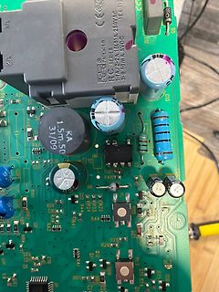
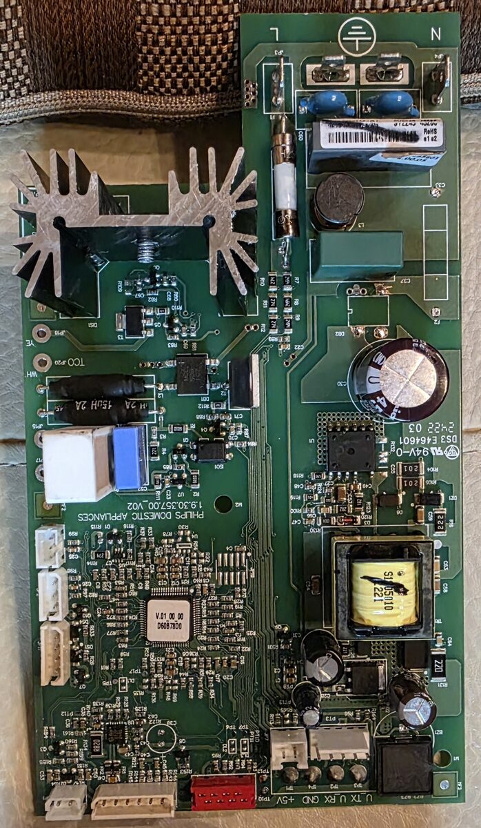
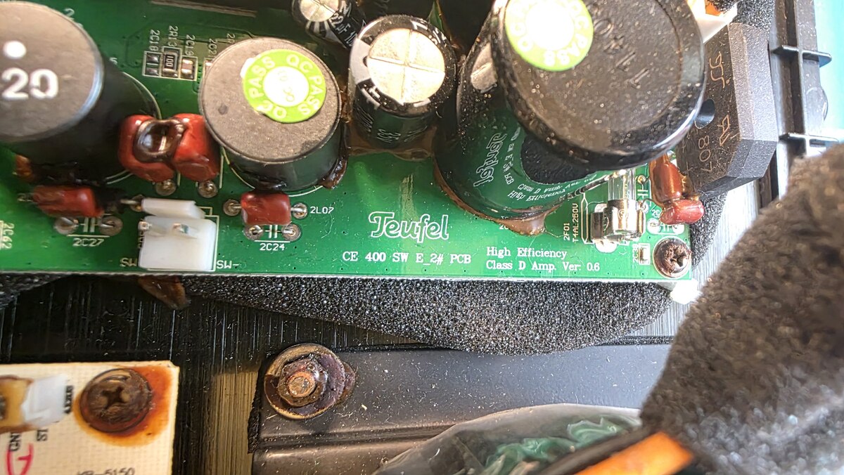
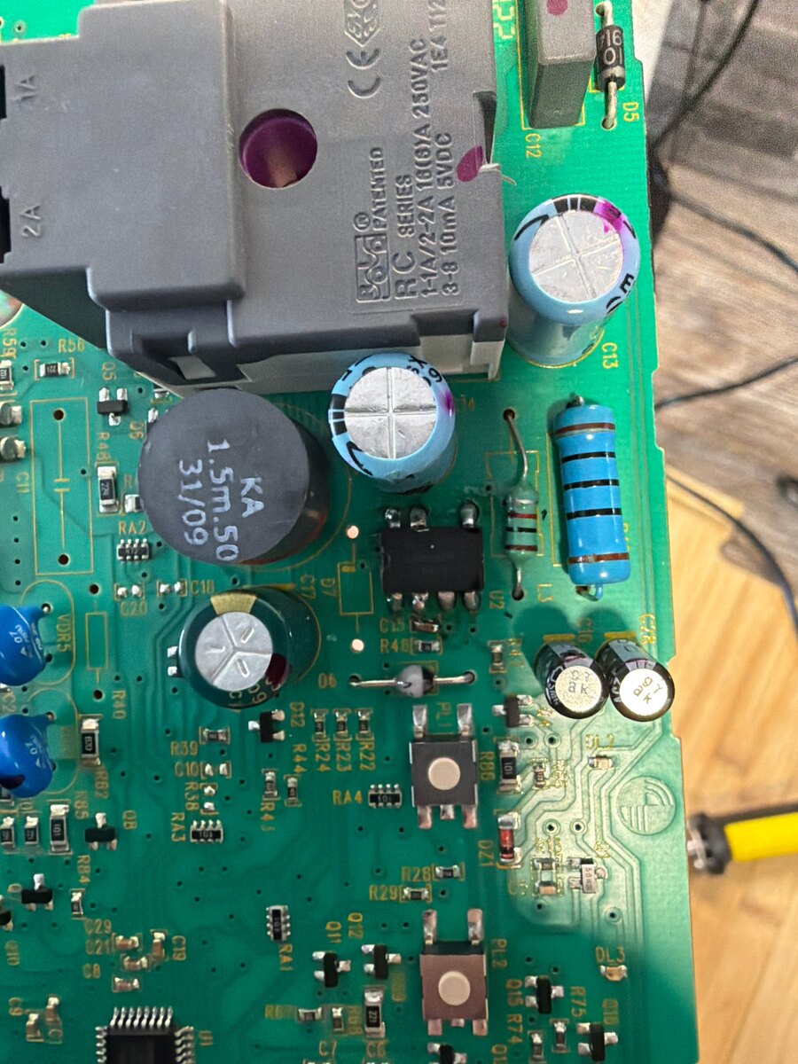
Hier die Links zu den Bildern. Kompletter Raum: https://www.photo-pick.com/online/bQV78HZZ.link Kleinteile: https://www.photo-pick.com/online/ebBNrqQf.link
#8085912: > Hier die Links zu den Bildern. > Kompletter Raum: https://www.photo-pick.com/online/bQV78HZZ. Wow. Das ist ne Menge Zeug, Aber hauptsächlich "Dickstromtechnik" wie man zu meiner Studienzeit gesagt hätte. Heutzutage am ehesten noch als Ersatzteilspender zu gebrauchen. Mein Lager ist da
-2, medical level, criteriaA MTBF 359.7Khrs min. MIL-HDBK-217F (25℃) OTHERS DIMENSION 127*76*42mm (L*W*H) PACKING 0.23Kg; 54pcs/14.6Kg/1.28CUFT NOTE 1. All parameters NOT specially mentioned are measured at 230VAC input, rated load and 25℃ of ambient temperature. 2. Ripple & noise are measured at 20MHz
h F h h h a t b u h t m a y i , h n ) ( l t t e ( l t 3 3 ( . g f , 5 u u u N e l g s i e r 1 l T ( c h M r f a 9 r f U V W e F n r 9. F T T T 1 2 3 4 g h s d r d r 3 m a e d a a H c e l l l F c e l l l t a d w F re a e g E e t c r f s r f M
IAXC Input current at AVSS < VIN< AV DD –500 +500 A CI+ and CI– V AOD Differential Output Voltage RL= 78 630 1200 mV |(DO+)–(DO–)| VAODOFF Transmit Differential Output RL= 78 (Note 5) –40 +40 mV Idle Voltage 1584 Am79C961 P R E L I M I N A R Y AMD DC CHARACTERISTICS over COMMERCIAL operating ranges unless
www.xlsemi.com 8 Datasheet 5A 180KHz 36V Buck DC to DC Converter XL4015 Package Information TO263-5L Dimensions In Millimeters Dimensions In Inches Symbol Min Max Min Max A 4.06 4.83 0.160 0.190 B 0.71 1.02 0.030 0.040 C 0.36 0.64 0.014 0.025 C2 1.14 1.40 0.045 0.055 D 8.39 9.65 0.330 0.380 E 9.78 10.54 0.385 0.415 e 1.55 1.85 0.061 0.073 F 6.36 7.36 0.250 0.290 L 13.95 15.37 0.549 0.605 L2 1.12 1.42 0.044 0.056 Rev 1.5 www.xlsemi.com 9 Datasheet 5A 180KHz 36V Buck DC to DC Converter XL4015 Important Notice XLSEMI reserve the right to make modifications, enhancements
Leads Insulated Flexible Leads 0.5 mm FRONT VIEW SIDE VIEW FRONT VIEW SIDE VIEW FRONT VIEW SIDE VIEW L T L T L T H H H S F LL 5 0 ± 5 5 3 1 ± ± F 8 8 S T H L F Nominal Tolerance Nominal Tolerance Nominal Tolerance Nominal Tolerance Nominal Tolerance 10.0 ± 0.4 4.0 +0.2/−0.5 9.0 +0.1/−0.5 13.0 +0.2/−0.5
Manfred L. schrieb im Beitrag #8074775: > Modellgeschwindigkeit messen? Modell im Kommandozeilenmodus laufen lassen (hier gemma4:e4b), dann "/set verbose" eingeben: [code] user@Ryzen7:~$ ollama run gemma4
Manfred L. schrieb im Beitrag #8074816: > PS C:\Windows\system32> ollama run llama3.3:70b > eval rate: 1.30 tokens/s Probier mal qwen3.6:35b https://ollama.com/library/qwen3.6 Das ist
f u – 0 0 [ l tr ° o p e 0 8 5 f d e u n 0 0 o o ] G P i m 0 l m . 2 7 c u [ A 0 0 e x D 2 C W 0 0 X y a 4 0 2 E 1 o M 2 ] 4 I 0 8 b y - 7 0 V . . t o P 0 0 M 0 0 a b [ 0 O 3 E p ti O . . T i I e l S 9 0 O e V t p
init (a); return a[i]; }[/c] Vorbereitug des Zugriffs: [avrasm] movw r30,r14 ; 95 [c=4 l=1] *movhi/0 lsl r30 ; 79 [c=8 l=2] *ashlhi3_const/0 rol r31 add r30,r16 ; 50 [c=8 l=2] *addhi3/0 adc r31,r17 ; Zugriff qua Z [/avrasm] Falls i an der Stelle nicht
[c]DATA = new byte[RF69_MAX_DATA_LEN];[/c] https://github.com/nurazur/TiNo2/blob/4f83f5759ea78e05a03c327c58b7edc5268cbe01/libraries/TiNo2/src/RFM69.h#L119 Nächste Frage ist also: Wie ist operator new definiert? Im MegaCoreX framework: [c]void *operator new(size_t size) { return malloc
Marcel L. schrieb im Beitrag #8072906: > ET66220 ET6622Q, und der ist nicht für Ausfälle berüchtigt. > Wenn ich am Ground vom 78M05 anlege und am > Ausgang von den RE1-5 messe, komme ich überall auf nahezu
Marcel L. schrieb im Beitrag #8072920: > Pin9 Ist V_LCD. Und R2i (2,2kOhm) ist der gesuchte Widerstand.
Überlastabschaltung greift. Du musst den Kurzschluss sekundär finden. Und: Der Kerko am Eingang des 78L05 fehlt.
Das hier könnte ich nehmen: HLK-PM09L - offene Bauform des HiLink HLK-09 mit 3Watt, arbeitet mit einem TL431, dessen Netzwerk man sicher auch auf 7.5V setzen kann. Ansonsten bliebe nur der Neukauf des ET Fotos siehe https://de.aliexpress.com
FILES ConfidAlesis S8-31-0127-Aal A B C D J J c c c c 11 1 1 h h h h 76 3 2 I I I I n n n n E E E E l l l l IL I L 4 3 2 1 e e e e NN N N 4 3 2 1 EE E E M M M M // / / C C C C A 86 8 6 J J J 4 3 2 1 c U 1 1 9 8 h X 1 0 n A l / J E C J I I 5 T 1 O L e C 2 U H 1 N N - E - N R 2 H R E E ) E ) O 8 N R L
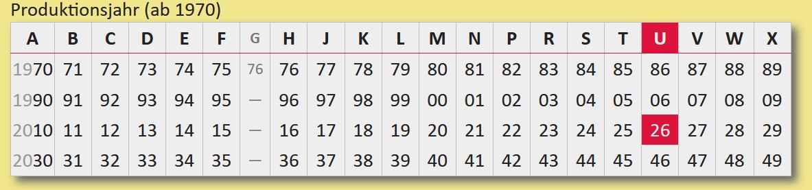
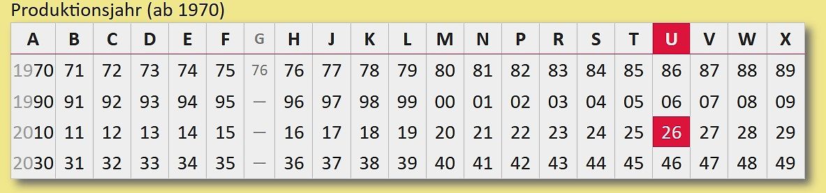
Produktionsjahr (ab 1970)
A B C D E F G H J K L M N P R S T U V W X
1970 71 72 73 74 75 76 76 77 78 79 80 81 82 83 84 85 86 87 88 89
1990 91 92 93 94 95 - 96 97 98 99 00 01 02 03 04 05 06 07 08 09
2010 11 12 13 14 15 - 16 17 18 19 20 21 22 23 24 25
60: < 61: = 62: > 63: ? 64: @ 65: A 66: B 67: C 68: D 69: E 70: F 71: G 72: H 73: I 74: J 75: K 76: L 77: M 78: N 79: O 80: P 81: Q 82: R 83: S 84: T 85: U 86: V 87: W 88: X 89: Y 90: Z 91: [ 92: \ 93: ] 94: ^ 95: _ 96: ` 97: a 98: b 99: c 100: d 101: e 102: f 103: g 104: h 105: i 106: j 107: k 108: l 109: m 110: n 111: o 112: p 113: q 114: r 115: s 116: t 117: u 118: v 119: w 120: x 121: y 122: z 123: { 124: | 125: } 126: ~ 127: 128: Ç 129: ü 130: é 131: â 132: ä 133: à 134: å 135: ç 136: ê 137:
bei. Ein Bild aus einer Kundenbewertung: https://imgaz.staticbg.com/customers_images/newlarge/89/78/2024102913583946-2006738.jpg
Manfred L. schrieb im Beitrag #8068393: > https://www.voelkner.de/products/11864782/VOLTCRAFT-DOV704-Digital-Oszilloskop-70MHz-4-Kanal-1.25-GSa-s-50-Mpts-12-Bit-Digital-Speicher-DSO-1St..html SMO804X
/` ç ] _0L U0L a L a a °°P î ² ] _0L U0L a L a U aî ² ] _0L U0L a L a U a²` R~î ] _0L U0L a L a U a"` °°Qî "_2L$U2L$a"LBa a °î ' X pk" PV p 0P Xp ¹ ]U_5LWU5LWa%LuaPaP° P R µP `ŽŠ 5Q b µP Ž0Q 0 0iPO @Y' § 'UeTŽZÿ
BCSRx register is set. If it ends successfully then the TXIF bit in the Interrupt Status Register 78/125 L9805E On-chip peripherals (ISR) is set, else the TEIF bit is set. An interrupt is generated in either case provided the TXIE and TEIE bits of the ICR register are set. The ETX bit in the same register
Dietrich L. schrieb im Beitrag #8067978: > Der Abstand der Leitung am unteren Pad von C2 ist auch zu klein. Nicht nur an C4. Und warum sind die Pads von den Steckern und Buchsen so mager? Gerade beim Einschrauben
Dietrich L. schrieb im Beitrag #8067978: > Der Abstand der Leitung am unteren Pad von C2 ist auch zu klein. Warum ist das im den Standard-Designrules von Kicad nicht drin, wenn es "common knowledge" ist ?
injection-current effect control 7. Functional description Table 3. Function table H = HIGH voltage level; L = LOW voltage level; X = don’t care. Input Channel ON E S2 S1 S0 L L L L Y0 to Z L L L H Y1 to Z L L H L Y2 to Z L L H H Y3 to Z L H L L Y4 to Z L H L H Y5 to Z L H H L Y6 to Z L H H H Y7 to Z H X X
Subject: C=US, ST=Washington, L=Redmond, O=Microsoft Corporation, CN=Microsoft Windows Production PCA 2011 [key 3] Owner: 77fa9abd-0359-4d32-bd60-28f4e78f784b SHA1 Fingerprint: 46:de:f6:3b:5c:e6:1c:f8:ba:0d:e2:e6:63:9c:10:19:d0
GMT Subject: C=US, ST=Washington, L=Redmond, O=Microsoft Corporation, CN=Microsoft Corporation UEFI CA 2011 [/c] Ist meine Annahme richtig, dass ich da bis 'Aug 23 23:59:59 2033 GMT' Ruhe habe?
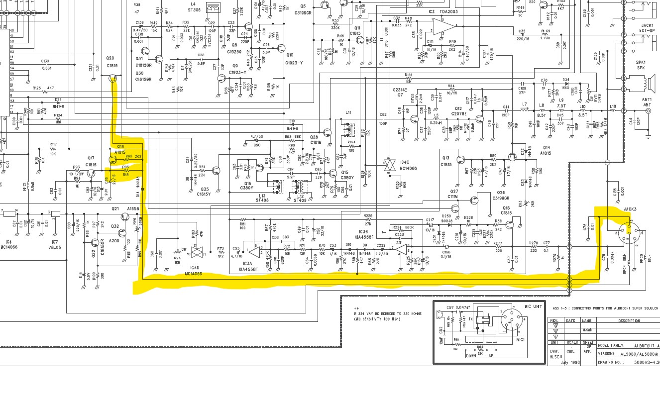
> an Q17 kommen, Dank der 9V1 Z-Diode D13, aus dem Emitter 8,5 V raus! Stimmt. Ich habe mich vom 78L05 täuschen lassen, aber der ist ja rückwärts gezeichnet und nicht die Quelle.
source codes for these modules are contained in the following files: M3LHBASE.A51 (basic routines for M3L-Bus transmission, using 3-wire bus protocol). MTXBASIC.A51 (MEGATEXT register control routines, see [6]). Instead of the M3LH module a programmer could de2ide to use either the M3LS (M3L-Bus driver using
-2.089 2.222 -5.45.97.204 195.145.119.188 2 u 164 256 377 17.170 -2.183 3.293 +78.47.56.71 129.134.28.123 2 u 52 256 377 7.675 -0.538 2.761[/pre] Dann hängt man den ESP32 ins gleiche Netz und trägt seine IP-Adresse in /etc/ntpsec/ntp.conf ein, nach den "pool"-Zeilen
ausgedacht, gewöhnliche Schüler können da nicht mitreden. 1) https://en.wikipedia.org/wiki/David_L._Mills
information about Turbo Roaming parameter settings, refer to the product manual. 2 www.moxa.com Typ. -78 @ 36 Mbps Typ. -74 @ 48 Mbps Typ. -73 @ 54 Mbps Note: Due to a limitation in the receiver sensitivity performance for channels 153 and 161, it is recommended to avoid using these channels in your critical
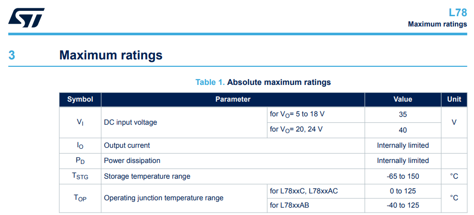
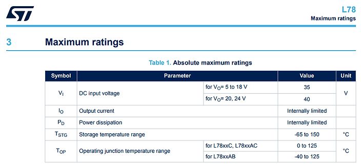
ST L78 Maximum ratings
3 Maximum ratings
Table 1. Absolute maximum ratings
Symbol Parameter Value Unit
VI DC input voltage for VO= 5 to 18 V 35 V
for VO= 20, 24 V 40
IO Output current Internally limited
PD
Register Offset FTMOPT0 Ch 11.3.1.3.2 Diagram Bits 31 30 29 28 27 26 25 24 23 22 21 20 19 18 17 16 R L L L L L L L L E E E E E E E E K K K K K K K K L L L L L L L L W 3 2 1 0 7 6 5 4 M M M M M M M M F F F F F F F F Reset 0 0 0 0 0 0 0 0 0 0 0 0 0 0 0 0 Bits 15 14 13 12 11 10 9 8 7 6 5 4 3 2 1 0 R L L
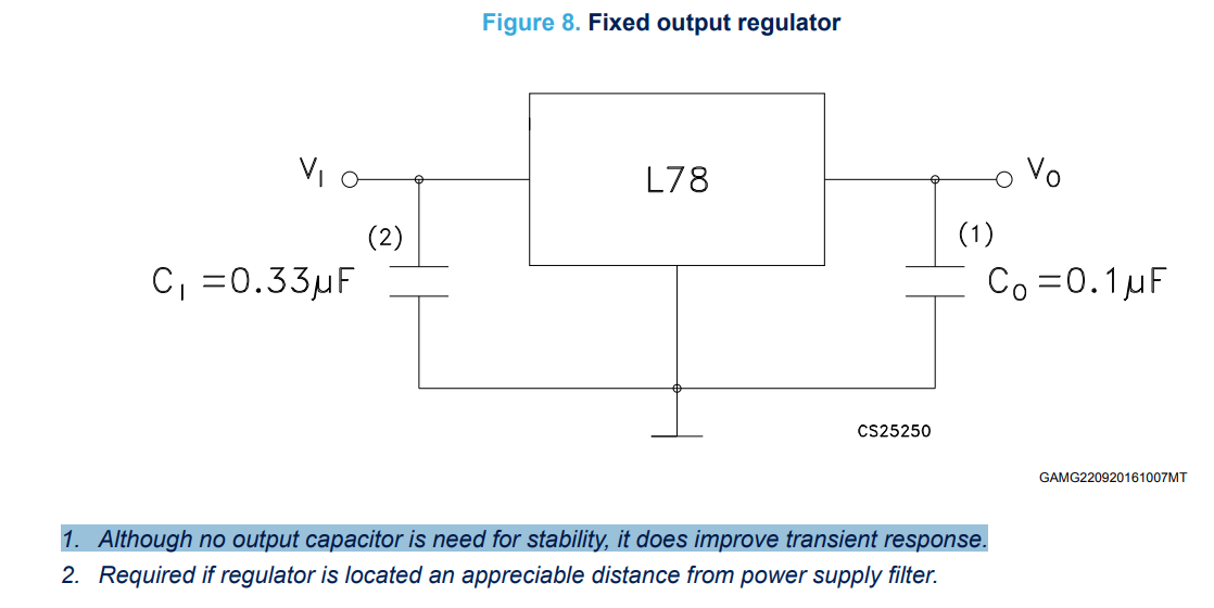
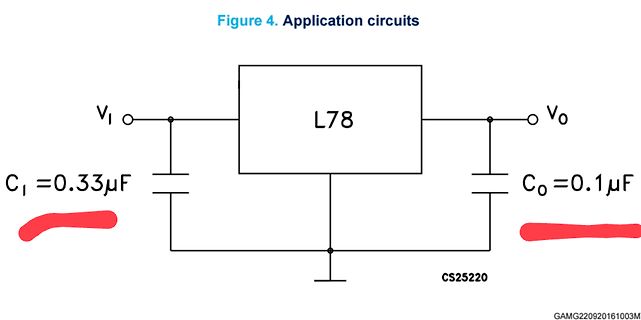
Figure 8. Fixed output regulator
L78
VI
(2)
CI = 0.33µF
VO
(1)
CO = 0.1µF
CS25250
GAMG220920161007MT
1. Although no output capacitor is need for stability, it does improve transient response.
2. Required if regulator is located an appreciable
Kondensatoren, darum aufschwingen 2. µC wird über seine ClampDioden versorgt, das überlastet den L7805
Hallo hat der L7805 nen Kühlkörper? Ab 1 Watt Verlustleistung braucht acuh ein TO220 einen Kühlkörper. Da reichen dann 50mA dass es ihm warm wird. Gruß
Das findet Gemini: Invasion vom Mars (Invaders from Mars, 1986) D.A.R.Y.L. – Der Außergewöhnliche (1985) Der Flug des Navigators (Flight of the Navigator, 1986) Cloak & Dagger – Ein kumpelhafter Typ (1984) Das Wunder in der 8. Straße (Batteries Not Included, 1987)
[code] Der Top-Kandidat: Die Insel der Ungeheuer (Originaltitel: The Island of Dr. Moreau / L'île mystérieuse) Es gibt eine sehr bekannte europäische Miniserie (die oft auch als zusammengeschnittener Spielfilm lief) aus dem Jahr 1973: "Die geheimnisvolle Insel" (L'île mystérieuse). [/code

 Bild
Bild
 Bild
Bild
 Bild
Bild
 Bild
Bild

 Bild
Bild
 Bild
Bild

 Bild
Bild
 Bild
Bild