-
PDF
slaa283a.pdf
a system using the 16-bit Sigma-Delta ADC integrated into the MSP430F2013 in order to detect motion is presented in this application report. 1 Hardware Design A system capable of detecting motion using a dual element PIR sensor is shown in Figure 1 using the MSP430F2013
in „Suche kleines, sparsames Bewegungssensormodul (PIR)“ · Mikrocontroller und Digitale Elektronik ·
-
PDF
EKG_usw_Informationformedicalapplications_von_TI.pdf
Pins/Packages Price Flash/ROM-Based F1xx Family V 1.8 to 3.6 V CC MSP430F1101A 1KB 128 14 — ✔ 3 — — — — — — ✔ slope — 20DGV,DW,PW,24RGE 0.99 MSP430C1101 1KB 128 14 — ✔ 3 — — — — — — ✔ slope — 20DGV,DW,PW,24RGE 0.60 MSP430F1111A 2KB 128 14
in „EKG Schaltung Neuling“ · Analoge Elektronik und Schaltungstechnik ·
-
Datei
msp430x20x2.h
TA2 module * ********************************************************************/ #ifndef __msp430x20x2 #define __msp430x20x2 #ifdef __IAR_SYSTEMS_ICC__ #ifndef _SYSTEM_BUILD #pragma system_include #endif #endif #if (((__TID__ >> 8) & 0x7F) != 0x2b) /* 0x2b = 43 dec */ #error MSP430X44X.H file
in „msp430x20x2.h gesucht“ · Mikrocontroller und Digitale Elektronik ·
-
PDF
slaa049.pdf
rw-0 rw-0 rw-0 rw-0 rw-0 rw-0 rw-0 rw-0 rw rw rw rw rw rw rw rw 7 0 7 0 URXBUF 27 26 25 24 23 22 21 20 UTXBUF 27 26 2 5 24 2 3 22 2 1 20 076h 077h r r r r r r r r rw rw rw rw rw rw rw rw Figure 5. USART Control Registers Used in the UART Mode MSP430 Universal Synchronous Asynchronous Receive/Transmit
in „[msp430] 9600 Baud mit 32kHz“ · Mikrocontroller und Digitale Elektronik ·
-
PDF
TI.pdf
voltage is fed into the integrated comparator and compared against a reference threshold. In the case of MSP430F5xx and MSP430F6xx devices, the shared reference module can provide up to 32 voltage reference levels, giving more flexibility in selecting an internal reference threshold. The comparator interrupt
in „Ansteuerung BrusslessDC Motor mit MSP430“ · Mikrocontroller und Digitale Elektronik ·
-
PDF
MSP430FR59xx.pdf
Documentation Feedback Copyright © 2012–2013, Texas Instruments Incorporated PRELIMINARY INFORMATION MSP430 and MSP430X Instructions www.ti.com 4.5.2 MSP430X Extended Instructions The extended MSP430X instructions give the MSP430X CPU full access to its 20-bit address space. Most MSP430X instructions require
in „Probleme mit Konfiguration der SPI-Schnittstelle am MSP430“ · Mikrocontroller und Digitale Elektronik ·
-
PDF
MSP430FR59xx.pdf
Documentation Feedback Copyright © 2012–2013, Texas Instruments Incorporated PRELIMINARY INFORMATION MSP430 and MSP430X Instructions www.ti.com 4.5.2 MSP430X Extended Instructions The extended MSP430X instructions give the MSP430X CPU full access to its 20-bit address space. Most MSP430X instructions require
in „Schaltung für Vibrationsmessung mit Piezo“ · Analoge Elektronik und Schaltungstechnik ·
-
PDF
SBLCDA2_Specification.pdf
allows for the addition of a backlight for nighttime viewing (SBLCDA2T only) • Operating temperature –20C/50C Typical Operation: The following graphs illustrate the SBLCDA2 and SBLCDA2Ts viewing angles for the range of V CC from 2.7v to 3.6v. The voltage was measured on pin 56 (R03) of the MSP430F449. This
in „MSP430FG439 mit LCD“ · Mikrocontroller und Digitale Elektronik ·
-
PDF
SBLCDA2_Specification.pdf
allows for the addition of a backlight for nighttime viewing (SBLCDA2T only) • Operating temperature –20C/50C Typical Operation: The following graphs illustrate the SBLCDA2 and SBLCDA2Ts viewing angles for the range of V CC from 2.7v to 3.6v. The voltage was measured on pin 56 (R03) of the MSP430F449. This
in „MSP430 LCD Controller“ · Mikrocontroller und Digitale Elektronik ·
-
PDF
SBLCDA4_Specifications.pdf
bias circuit allows adjustment for viewing angle, contrast, and temperature • Operating temperature –20C/50C Typical Operation The following graphs illustrate the SBLCDA4 viewing angles for the range of V CC from 2.7v to 3.6v. The test was performed on an MSP430F413. The voltage measured was on pin 40 (R03) of the MSP430F413. This is the input port of the lowest analog LCD level (V5). The voltage was controlled by a 200kΩ potentiometer. Due to the wide viewing angle of the SBLCDA4 your bias voltage may vary from
in „MSP430 Experimentierboard - LCD (SBLCDA4)“ · Mikrocontroller und Digitale Elektronik ·
-
PDF
slaa044.pdf
Usingthefixedpulsedurationisrecommendedtoreducethepowerconsumption in battery-powered applications. MSP430 IrDA SIR Encoder/Decoder 3 The MSP430x112 – Low-End Ultra-Low Power Microcontroller 3 The MSP430x112 – Low-End Ultra-Low Power Microcontroller TheMSP430x112isthesmallestmemberoftheMSP430family,a16
in „MSP430 - IrDA Empfänger“ · Mikrocontroller und Digitale Elektronik ·
-
PDF
430JTAG.pdf
1 2 3 4 D D MSP430 JTAG R11 CTDO JP1 R18 R2 330R R1 CRST 1 EN_TCLK 33K 33K 33K 2 CTDI CTDI R3 UA R12 M25HP284 3 CTMS CTMS 33K 2 18 330R 4 CTST CTST 4 A1 Y1 16 C 25 13 6 CTCK CTCK R4 6 A3 Y3 14 R13 JP2 C 24 12 CTDO
in „MSP430 JTAG -> Layout gesucht“ · Mikrocontroller und Digitale Elektronik ·
-
Datei
msp430x20x2_adc10_14_Beispiel_von_TI_.cpp
//****************************************************************************** // MSP430F20x2 Demo - ADC10, DTC Sample A1-0 16x, AVcc, Repeat Seq, DCO // // Description: Use DTC to sample A1/A0 repeat sequence 16x(32 total samples) // with reference to AVcc. Software sets ADC10SC to
in „MSP430 Leistungsmessung 230V“ · Mikrocontroller und Digitale Elektronik ·
-
Datei
msp430f66xx_adc_10.c
//****************************************************************************** // MSP430F66xx Demo - ADC12, Sample A10 Temp and Convert to oC and oF // // Description: A single sample is made on A10 with reference to internal // 1.5V Vref. Software sets ADC12SC to start sample and conversion
in „Brauche Hilfe beim abändern eines Examples von TI.“ · Mikrocontroller und Digitale Elektronik ·
-
Datei
main.c
//****************************************************************************** // MSP430F20x2/3 Demo - SPI full-Duplex 3-wire Master // // Description: SPI Master communicates with SPI Slave RFM12 868MHz // using 3-wire mode. // Master will pulse slave reset for synch start. // ACLK = n/a, MCLK = SMCLK = Default DCO // // Slave Master // RFM12 Transceiver MSP430F2013 // ----------------- ----------------- // | | /|\| XIN|- // | | | | | // | | --|RST XOUT|- // VCC->|VDD | | | // VCC-10K ->|FSK/DATA | | | // GND ->|GND (7&10) | | | // | | | P1.0|-> LED //
in „RFM12 + MSP2013“ · Mikrocontroller und Digitale Elektronik ·
-
Datei
fet140_dma_09.c
//******************************************************************************* // MSP-FET430P140 Demo - DMA0, ADC12 A10 Block Xfer to RAM, TBCCR1, DCO // // Description: A 0x20 word block of data is sampled and recorded into RAM // from the ADC12 channel 10 the integrated temperature
in „MSP430: ADC12 soll DMA triggern“ · Mikrocontroller und Digitale Elektronik ·
-
Datei
msp430f149.h
**************************** * * Standard register and bit definitions for the Texas Instruments * MSP430 microcontroller. * * This file supports assembler and C development for * MSP430x14x devices. * * Texas Instruments, Version 2.4 * * Rev. 1.2, Additional Timer B bit definitions. * Renamed XTOFF
in „MSP430 Portfehler“ · Mikrocontroller und Digitale Elektronik ·
-
Datei
msp430x20x2_adc10_10.c
//****************************************************************************** // MSP430F20x2 Demo - ADC10, DTC Sample A2-0, AVcc, Single Sequence, DCO // // Description: Sample A3/A2/A1 as single sequence with reference to AVcc. // Software sets ADC10SC to trigger sample sequence. In
in „MSP430 ADC10: Zwei Kanäle hintereinander abfragen“ · Mikrocontroller und Digitale Elektronik ·
-
PDF
slau056e.pdf
off DC DCO + Generator Modulator FLLDx fDCOCLK DCOPLUS DCO Divider /1/2/4/8 SELS 1 fDCO/D SMCLKOFF 0 0 0 1 1 XT20FF SMCLK XT2IN XT2OUT XT2 Oscillator FLL+ Clock Module 4-3 Figure 4−2.MSP430x42x and MSP430x41x Frequency-Locked Loop FLL_DIVx
in „MSP430 LCD Controller“ · Mikrocontroller und Digitale Elektronik ·
-
PDF
slau056e.pdf
off DC DCO + Generator Modulator FLLDx fDCOCLK DCOPLUS DCO Divider /1/2/4/8 SELS 1 fDCO/D SMCLKOFF 0 0 0 1 1 XT20FF SMCLK XT2IN XT2OUT XT2 Oscillator FLL+ Clock Module 4-3 Figure 4−2.MSP430x42x and MSP430x41x Frequency-Locked Loop FLL_DIVx
in „MSP430FG439 mit LCD“ · Mikrocontroller und Digitale Elektronik ·
-
PDF
slau049f.pdf
for the LFXT1 Oscillator XTS OSCOFF LFoff CPUOFF SELM1 XT1off XT2 XT2 is an Internal Signal XT2 = 0: MSP430x11xx, MSP430x12xx devices SCG1 XT2 = 1: MSP430x13x, MSP430x14x SELS MSP430x15x, and MSP430x16x devices Note: LFXT1 Oscillator Characteristics Low-frequency crystals often require hundreds of milliseconds
in „Umrechnung: C-Code->Assembler-Code->Cycles“ · Mikrocontroller und Digitale Elektronik ·
-
Datei
msp430x20x3_usi_05.c
//****************************************************************************** // MSP430F20x2/3 Demo - USI SPI Interface to TLC549 8-bit ADC // // Description: This program demonstrates the USI in SPI mode interface to a // TLC549 8-bit ADC. If AIN > 0.5(REF+ - REF-), P1.0 set, else
in „MSP430 MSP430F2013 SPI Kommunikation mit D/A-Wandler“ · Mikrocontroller und Digitale Elektronik ·
-
Datei
msp430x20x3_P1_02.c
//****************************************************************************** // MSP430F20xx Demo - Software Port Interrupt Service on P1.4 from LPM4 // // Description: A hi/low transition on P1.4 will trigger P1_ISR which, // toggles P1.0. Normal mode is LPM4 ~ 0.1uA. LPM4 current
in „MSP Interruptroutine“ · Mikrocontroller und Digitale Elektronik ·
-
Datei
main.c
//***************************************************************************** // MSP-FET430P140 Demo - DMA0, Rpt'd Blk to DAC0, Sine Output, TACCR1, DCO // // Description: DMA0 is used to transfer a sine look-up table word-by-word // as a repeating block to DAC12_0. The effect is sine
in „Bitte, bitte helft mir: MSP430 DMA Problem“ · Mikrocontroller und Digitale Elektronik ·
-
PDF
slau049f.pdf
. This chapter discusses the operation of the asynchronous UART mode. USART0 is implemented on the MSP430x12xx, MSP430x13xx, and MSP430x15x devices. In addition to USART0, the MSP430x14x and MSP430x16x devices implement a second identical USART module, USART1. Topic Page 13.1 USART Introduction: UART
in „MSP430: UART Verständnis/Problem“ · Mikrocontroller und Digitale Elektronik ·
-
Datei
DUCSPI.c
* * * * *******************************************************************************/ #include <msp430x20x3.h> // Header for MSP430F2013, located at C:\Programme\IAR Embedded Workbench\430\inc //Function prototypes void spi_init(void); // Initialization of SPI for converters void v_out(char,char);
in „MSP430 MSP430F2013 SPI Kommunikation mit D/A-Wandler“ · Mikrocontroller und Digitale Elektronik ·
-
Datei
DUCSPI.c
* * * * *******************************************************************************/ #include <msp430x20x3.h> // Header for MSP430F2013, located at C:\Programme\IAR Embedded Workbench\430\inc //Function prototypes void spi_init(void); // Initialization of SPI for converters void v_out(char,char);
in „Mit MSP430F2013 Daten senden“ · Mikrocontroller und Digitale Elektronik ·
-
Datei
msp430x20x3_ta_uart2400.c
//****************************************************************************** // MSP430F20xx Demo - Timer_A, Ultra-Low Pwr UART 2400 Echo, 32kHz ACLK // // Description: Use Timer_A CCR0 hardware output modes and SCCI data latch // to implement UART function @ 2400 baud. Software does
in „UART und SPI mit MSP430 (MSP430F2013), Pin-Konflikt“ · Mikrocontroller und Digitale Elektronik ·
-
Datei
msp430x20x3_ta_uart2400.c
//****************************************************************************** // MSP430F20xx Demo - Timer_A, Ultra-Low Pwr UART 2400 Echo, 32kHz ACLK // // Description: Use Timer_A CCR0 hardware output modes and SCCI data latch // to implement UART function @ 2400 baud. Software does
in „MSP430F20xx UART“ · Mikrocontroller und Digitale Elektronik ·
-
Datei
MAX5530.txt
#include "msp430x20x3.h" //Header for MSP430F2013, located at //C:\Programme\IAR Embedded Workbench\430\inc //Function prototypes void spi_init(void); //Initialization of SPI void v_out(void); //Set output voltage
in „MSP430 MSP430F2013 SPI Kommunikation mit D/A-Wandler“ · Mikrocontroller und Digitale Elektronik ·
-
Datei
main.c
//****************************************************************************** // MSP430F20xx Demo - Timer_A, Ultra-Low Pwr UART 2400 Echo, 32kHz ACLK // // Description: Use Timer_A CCR1 hardware output modes and SCCI data latch // to implement UART function @ 2400 baud. Software does
in „UART und SPI mit MSP430 (MSP430F2013), Pin-Konflikt“ · Mikrocontroller und Digitale Elektronik ·
-
PDF
snlu184.pdf
and a high speed interface slave device. Communication between the PC and the interface adapter’s MSP430F5529 MCU is accomplished with a standard USB-to-miniUSB cable. The MCU then communicates to the slave device via SMBus or SPI interface. Figure 1. DPS-DONGLE-EVM Board (Front). Figure 2. DPS-DONGLE-EVM
in „Tastatur komplett selbst erstellen“ · PC Hard- und Software ·
-
Datei
LCD.c
/ /* Aufgabe: Initialisierung des LCD Controllers */ /* */ /* System: Controller Texas Instruments MSP430F449 */ /* Compiler CrossStudio for MSP430 Version 1.4 */ /*----------------------------------------------------------------------------*/ /* Funktionen: init_LCD */ /* clear_LCD */ /* display_LCD
in „MSP430FG439 mit LCD“ · Mikrocontroller und Digitale Elektronik ·
-
Datei
main.c
------------------------------------------------------------- controls a EA DOGM162x-x LCD by a TI MSP430x12x2, MSP430x22x2 or MSP430x22x4 ---------------------------------------------------------------------------- connect the LCD in seriell (SPI) or parallel (4bit or 8bit) mode an select the right
in „DOGM162 an MSP430F1232 betreiben“ · Mikrocontroller und Digitale Elektronik ·
-
PDF
Ultraschall.pdf
Sequenz an die Leistungsstufe des Senders ¨bergibt. Als ein solcher Microcontrol¨er kame zu Beispiel der MSP430 von Texas Instruments in Frage, da dieser durch seinen niedrigen Energiever- brauch, grossen RAM und die vorhandenen Schnittstellen die Anforderungen zur Verwendung in einer Bake er¨ullen kann [6
in „schnelle Entfernungsmessung“ · Mikrocontroller und Digitale Elektronik ·
-
PDF
ElektronikBauteile.pdf
, mit Verrieglung, gerade PSL 20 0,37 € 0,74 € 83 2 Pfostenstecker, 20-polig, mit Verrieglung, gew. PSL 20W 0,59 € 1,18 € 84 0,66 Flachbandkabel AWG28, 24-pol., farb., 3m-Ring AWG 28-24F 3M 9,45 € 6,24 € ~2m übrig 85 10 Hohlstecker,
in „[V] - Elektroniksammlung“ · Markt ·
-
Datei
VirtualWire.cpp
Exp mikem $ #if defined(ARDUINO) #if (ARDUINO < 100) #include "WProgram.h" #endif #elif defined(__MSP430G2452__) || defined(__MSP430G2553__) // LaunchPad specific #include "legacymsp430.h" #include "Energia.h" #else // error #error Platform not defined #endif #include "VirtualWire.h" #include <util/
in „Korrigierte "VirtualWire" Library für Attiny84 / 85“ · Projekte & Code ·
-
Datei
FET140_demolist_C.txt
i2c_03.c - I2C, Master Interface to DAC8571 in Repeat Mode fet140_i2c_04.c - I2C, Master Reads from MSP430 Slave fet140_i2c_05.c - I2C, Slave Transmits to MSP430 Master fet140_i2c_06.c - I2C, Master Transmits to MSP430 Slave RX fet140_i2c_07.c - I2C, Slave Reads from MSP430 Master fet140_i2c_08.c - I2C, Master Writes Multiple Bytes to MSP430 Slave fet140_i2c_09.c - I2C, Master Reads from MSP430 Slave in Repeat Mode fet140_i2c_10.c - I2C, Slave Writes to MSP430 Master RX in Repeat Mode fet140_i2c_12.c - I2C, Master Interface to DAC8571
in „MSP430 UART Baudrate einstellen“ · Mikrocontroller und Digitale Elektronik ·
-
Datei
Wandler-Test.c
decimal *******************************************************************************/ #include <msp430x20x3.h> // Header for MSP430F2013, located at C:\Programme\IAR Embedded Workbench\430\inc //Function prototypes void spi_init_conv(void); // Initialization of SPI for converters void v_out(int);
in „MSP430 MSP430F2013 SPI Kommunikation mit D/A-Wandler“ · Mikrocontroller und Digitale Elektronik ·
-
Datei
main.c
******************************************************************** // Testcode Hardware PWM with MSP430F149/MSP430F1611 // //description: // no main functionality // clock is set by DCO , rd. 4MHz // timer B use the Outputs 4.1/4.2/4.3 // timerA update the compare value and look in pwmtable for the
in „variable PWM mit MSP430“ · Mikrocontroller und Digitale Elektronik ·
-
Datei
A--0191c-i-DS10_be-kon_Ka09_b.c
***** // * Datenspeicher 10 * // ******************* // Flüssigkristallanzeige LMK62R125A1 // DS18B20 NR. 13,14,15,16 an 63-10 Adresse 0x18 // E32-868T Funk ab 29.8.21 //Änderungen: /************************************************************************/ // MSP430F1611 // ----------------- // | XIN
in „Sende/Empfangsvorgang mittels nur 1St. µC“ · Mikrocontroller und Digitale Elektronik ·
-
Datei
DS10-g0075-PID.c
/* Messstelle 4 = Spannungseingang P6.0 */ //rechts Kanal 4 /* Akku = Spannungseingang P6.1 */ // MSP430F1611 // ----------------- // | XIN|- 32,768kHz // | | | // Taster rot--|RST (58) XOUT|- 32,768kHz //8 MHz X2OUT- | P1.0..P1.7| Daten FKA LMK62 //8 Mhz X2IN- | | // | P3.0| Motorsteuerung A // UTXD0
in „Wie 2x interrupt verschachteln, MSP430“ · Mikrocontroller und Digitale Elektronik ·
-
Datei
bauteile_001.txt
------------------------------------------------------------------------- 80 74LVX244 SO Fairchild 20 2,00 300 74LVC244 TSSOP 50 5,00 30 74HCT138 SO Philips 30 2,00 50 NE555 SO TI 25 2,00 10 AT89C4051-24PI DIL Atmel 5 2,00 7 SX28AC/DP DIL Ubicom 7 5,00 3 PIC18F4539-I/P DIL Microchip 3 6,00 3 PIC16F88
in „Verkaufe diverse Bauteile“ · Markt ·
-
 Bild
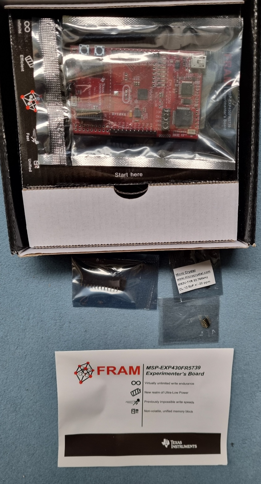
Texas Instruments MSP-EXP430FR5739 Experimenter's Board in Verpackung
MSP-EXP430FR5739 Experimenter's Board infinite efficient fast unlimited Start here Micro Crystal www.microcrystal.com MSP2-T1R 33-80Hz CL 12 nF +/- 20 ppm FRAM MSP-EXP430FR5739 Virtually unlimited write
in „[V] TI FRAM MSP-EXP430FR5739 Experimenter's board“ · Markt · · Fotos
-
Datei
bauteile_003.txt
------------------------------------------------------------------------- 80 74LVX244 SO Fairchild 20 2,00 300 74LVC244 TSSOP 50 5,00 30 74HCT138 SO Philips 30 2,00 50 NE555 SO TI 25 2,00 7 SX28AC/DP DIL Ubicom 7 5,00 3 PIC18F4539-I/P DIL Microchip 3 6,00 3 PIC16F88-I/P DIL Microchip 3 3,00 3 PIC16C58B/JW DIL Microchip 3 3,00 2 PIC16C56A/JW DIL Microchip 2 2,00 6 PIC18F242-I/SP DIL Microchip 3 3,00 3 LPC2101F TQFP 3 3,00 9 MSP430F1121A TSSOP TI 9 4,00 5 MSP430F149I LQFP TI 5 9,00 60 29F040C-70 PLCC 60 6,00 1 10 25P10AVG ST 10 3,00 1) Hierbei handelt es sich um Schüttgut
in „Verkaufe diverse Bauteile“ · Markt ·
-
Datei
bauteile_002.txt
------------------------------------------------------------------------- 80 74LVX244 SO Fairchild 20 2,00 300 74LVC244 TSSOP 50 5,00 30 74HCT138 SO Philips 30 2,00 50 NE555 SO TI 25 2,00 10 AT89C4051-24PI DIL Atmel 5 2,00 7 SX28AC/DP DIL Ubicom 7 5,00 3 PIC18F4539-I/P DIL Microchip 3 6,00 3 PIC16F88
in „Verkaufe diverse Bauteile“ · Markt ·
-
Datei
DS10-g0074-PID.c
/* Messstelle 4 = Spannungseingang P6.0 */ //rechts Kanal 4 /* Akku = Spannungseingang P6.1 */ // MSP430F1611 // ----------------- // | XIN|- 32,768kHz // | | | // Taster rot--|RST (58) XOUT|- 32,768kHz //8 MHz X2OUT- | P1.0..P1.7| Daten FKA LMK62 //8 Mhz X2IN- | | // | P3.0| Motorsteuerung A // UTXD0
in „Wie 2x interrupt verschachteln, MSP430“ · Mikrocontroller und Digitale Elektronik ·
-
Datei
DS10-g0133-PID.c
/* Messstelle 4 = Spannungseingang P6.0 */ //rechts Kanal 4 /* Akku = Spannungseingang P6.1 */ // MSP430F1611 // ----------------- // | XIN|- 32,768kHz // | | | // Taster rot--|RST (58) XOUT|- 32,768kHz //8 MHz X2OUT- | P1.0..P1.7| Daten FKA LMK62 //8 Mhz X2IN- | | // | P3.0| Motorsteuerung A // UTXD0
in „while-Schleife wird "unerlaubt verlassen"“ · Mikrocontroller und Digitale Elektronik ·
-
Datei
control1.c
#include <msp430x16x.h> #include <msp430def.h> void timera_init(); void timerb_init(); void mittel(); void init_DAC(); void init_SIO(); void init_ADC(); void wait_05ms(); #pragma interrupt_handler timera_isr: TIMERA0
in „MSP430 Timing Probleme“ · Mikrocontroller und Digitale Elektronik ·
-
Datei
bmp085.c
#include "msp430x22x4.h" //#define NUM_BYTES_TX 3 // How many bytes? #define NUM_BYTES_RX 2 // anzahl zu empfangenden bytes fix unsigned char NUM_BYTES_TX; // anzahl zu sendender bytes variiert int RXByteCtr, RPT_Flag
in „msp430f2274 bmp085 i2c ohne interrupt“ · Mikrocontroller und Digitale Elektronik ·