models No. S116S02) diode (IRED), a Phototriac Detector and a main output 2. Approved by CSA 22.2 No.14 (only for S116S02 Triac. These devices are ideally suited for controlling Series), file No. LR63705 (as models No. S116S02) high voltage AC loads with solid state reliability while 3. Package resin :
Hohlstecker liegt dann auf PE. Bei denen mit Euro-Stecker zappelt GND irgendwo (hochohmig) bei 100 V AC herum, kapazitiv über Trafo und Y-Kondensatoren eingekoppelt. Manchmal hilft's den Stecker zu drehen... PE wäre mir in der Fritzbox da lieber.
kombiniert mit einer Buchse. Das Gegenteil findet man an (z.B.) zig Staubsaugern. Ansonsten C13 & C14 mal suchen... Männlein, Weiblein & alles dazwischen *lachend* // Ihr seid ein cooler Haufen - danke!
> Die großen machen es sogar schon ab 14Hz. Nonplusultra war, von vor 50 Jahren,als noch in D produziert wurde, folgender 30cm-Tieftöner. Der ging bis 22 Hz, das ist auch schon tief: https://www.radiomuseum.org/r/isophon_tiefton_lautsprecher_psl
man Kanaltrennung und Dynamik ignoriert, und sich > ausschließlich auf das obere, und für alle über 14jährigen Menschen > eh' nicht mehr hörbare Frequenzspektrum > 20 kHz beschränkt, dann trifft > der Spruch zu). Hast Du mal eine Direktschnittschallplatte ueber ein wirklich gute Anlage gehoert? Ich
VC1008) tut das so. Ich habe nachgefragt bezüglich Techn. Daten des Multimeters. Wechselspannung(AC) • Max. Eingangsspanung: 600 V AC • Frequenzbereich: 40...1000 Hz Gilt 1000Hz auch für das Oszilloskop? Mit dem könnte ich doch auch die VAC darstellen.
nicht aus dem vorletzten Jahrhundert ist, und der DC mit einem "Kupferoxydulgleichrichter" aus dem AC gemacht wird. Dann ist schon eher Schluss. Man muss nicht nach allem was nach Spannung aussieht, mit einem Oszi werfen...
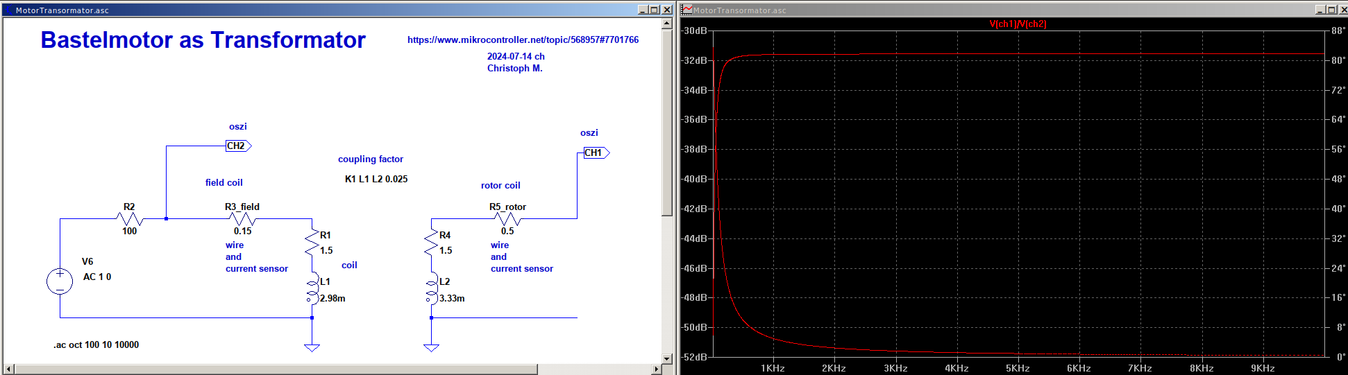
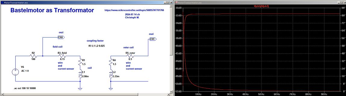
MotorTransformator.asc
Bastelmotor as Transformator
https://www.mikrocontroller.net/topic/568957#7701766
2024-07-14 ch
Christoph M.
oszi CH2
field coil
R2 100
R3 field 0,15 wire and current sensor
V6 AC 10
oszi CH1
coupling factor K1 L1 L2 0,025
rotor coil
R4 0,5 wire and current sensor
R5 rotor 1,5
L1 2.98m
L2 3.33m
referenced to 4 STROBE O Strobe VDD. When output = VDD -5V, it enables other internal circuits. 5,14 VDD, GND Power supply To supply the power To output pulse drive signal for 6 IRED O Output signal external NPN transistor which drives a IR photodiode. It can be used to connect up to 40 7 I/O Input/
verlinktem Datenblatt. Auch das Komma darf nicht direkt an DC angeschlossen werden, sondern benötigt ein AC-Signal. Beachtet man das nicht, wird das LCD schnell beschädigt.
auf genau 4,80V > einzustellen? Schalte einfach zwischen den beiden 220k Widerständen R13 und R14 noch einen 100k Spindeltrimmer, damit kannst du dir dann deinen gewünschten Schaltpunkt exakt einstellen.
Programm 36 VA: https://www.conrad.de/de/p/elma-tt-iz59-universal-netztransformator-1-x-230-v-2-x-10-v-ac-12-v-ac-15-v-ac-36-va-1-20-a-514764.html 66 VA: https://www.conrad.de/de/p/elma-tt-iz65-universal-netztransformator-1-x-230-v-2-x-10-v-ac-12-v-ac-15-v-ac-66-va-2-20-a-514780.html aber da gibt es keinen
Sekundärwicklungen einzeln herausgeführt (bei den UE4, UE5, UE6, UE10, UE11, UE12 wäre genug Platz für die 14 Lötösen), gäbe es deutlich mehr Möglichkeiten.
Gegend von 1000Euro bezahlt habe. https://www.reichelt.de/de/de/regeltrenntransformator-0--250-v-ac-br-351-p100665.html?r=1 https://www.reichelt.de/regeltrenntransformator-250-v-ac-4-5-a-galvanische-trennung-peaktech-2235-p101936.html Also Wert ist die Kiste auf jedenfall einiges, bloss halt
Benutzername dariusd Vorname Darius Angemeldet seit 27.05.2024 13:14 Beiträge 71 Tja Darius, du bist noch frisch wenn Du mal mehr als 2 Monate dabei bist wirst Du sehen: So läuft es nun mal in diesem Forum. Geschenkt ist noch zu teuer ,-)
Portable Equipment Battery-Powered Instrumentation Pin Configurations (Top View) HTC8634 HTC8632 TSSOP-14/SO-14 HTC8631 MSOP-8/SO-8 SC70-5/SOT23-5 OUT A 1 14 OUT D OUT A 1 8 ﹢V S ﹣IN A 2 13 ﹣IN D OUT 1 5 ﹢V S A D ﹣IN A 2 A 7 OUT B ﹢IN A 3 12 ﹢IN D ﹣V S 2 3 6 ﹢IN A B ﹣IN B ﹢V S 4 11 ﹣V S ﹢IN 3 4 ﹣IN ﹣V 4
Portable Equipment Battery-Powered Instrumentation Pin Configurations (Top View) H0▯▯▯4 H0▯▯▯2 TSSOP-14/SO-14 H0▯▯▯1 MSOP-8/SO-8 SC70-5/SOT23-5 OUT A 1 14 OUT D OUT A 1 8 ﹢V S ﹣IN A 2 13 ﹣IN D OUT 1 5 ﹢V S A D ﹣IN A 2 A 7 OUT B ﹢IN A 3 12 ﹢IN D ﹣V S 2 3 6 ﹢IN A B ﹣IN B ﹢V S 4 11 ﹣V S ﹢IN 3 4 ﹣IN ﹣V 4 5
blauen Kasten machst. Je nach dem, was an J1 angeschlossen ist, mag es ungünstig sein, wenn die TriAC die Pins kurz schließt
Eingangsschaltung scheinen wohl nur die Programmiersignale zu sein. Wenn es allein um einen Teiler 14:1 oder 7:1 geht, kann man doch einfach einen 4017 nehmen. Was das dann überhaupt bringen soll, bleibt mir allerdings schleierhaft. Schönen Freitag noch! ;-)
Cell-Phone Charger line sense resistors R2 and R3 sense the DC input voltage As an example, Figure 14 shows a TNY264 based 5 V, for line under-voltage. When the AC is turned off, the under- 0.5 A, cellular phone charger operating over a universal input voltagedetectfeatureoftheTinySwitch-IIpreventsauto-restart
the wiring inductance between the MOSFETs and the decoupling capacitors; L S1 and L D2 are in an “AC path” and are due to the wiring inductance between the MOSFETs. The stray inductance in a DC path can be cancelled with a capacitor; those in an AC path cannot be compensated for. To eliminate the effects
Schau dir mal den CD4046 an, da schließt du einfach die Soll- und die Istfrequenz an Pin 3 und an Pin 14 an und aus Pin 13 kommt das fertige Schaltsignal raus. Der Vergleichsoszillator ist bereits im CD4046 integriert, du brauchst nur noch ein RC-Glied und ein Poti anzuschließen.
ein An-Aus Signal generieren möchte. Aber grundsätzlich ist die Idee gar nicht so schlecht ein AC Relais über einen Kondensator anzusteuern, vielleicht nicht ganz so präzise aber man hat eine Hysterese, wenn auch nicht wirklich einstellbar, aber wenn es zur Anwendnung passt keine schlechte Idee
THE ELECTRIC WIRE, INSURE THAT INSULATION TAPE IS APPLIED TO PREVENT AN ELECTRICAL SHORT. M O DEL:F14A8YD(1~ 9)/S44A8YD CONTENTS 1. SPECIFICATIONS ............................................................................................................................. 3 2. FEATURES & TECHNICAL EXPLANATION
betrüge dann 1/20 V/LSB, um vom ADC-Wert auf die Spannung umzurechnen. Oder bei Auslegung auf 3.14V für 40V wäre es ein Faktor von 1/16 V/LSB. Oder der GPIO wird einfach als digitaler Eingang benutzt 😄
> > Es gibt 36V DC als Spulspannung. Spulspannung? Und jetzt doch DC. Oben fragst Du noch ob AC oder DC.
through ●● Miniature 8-Pin SOT23 Package notification of code execution errors. The family offers ●● AEC-Q100 Qualified (MAX6369KA/V+ and several pin-selectable watchdog timing options to match MAX6374KA/V+ Only) a wide range of system timing applications: Applications ●● Watchdog startup delay: provides
1,5kW lt Datenblatt. Sie sterben regelmäßig > an 2kW Heizung. Aus dem Finder-Datenblatt 28.06.2024 14:02: Max. Schaltleistung AC1 VA 7.500 (S) Max. Schaltleistung AC15 (230 V AC) VA 1.200 (S) 1-Phasenmotorlast, AC3 - Betrieb (230 V AC) kW 1,5 (S) Kann jemand mit einfachen Worten diese "AC1 /
Manfred P. schrieb im Beitrag #7693775: > Kann jemand mit einfachen Worten diese "AC1 / AC15 .." erklären? Darf es auch ein Link sein? https://www.elesta-gmbh.com/relais/relais-wissen/lasten/uebersicht-herkoemlicher-gebrauchskategorien/
1 Q14 = 1 = 3 1 2 0 r R r R C3 1 8 } IXTP10P50P 2 2 1n 2 R r 1 2 r 2 V 3 1 C12 2 u 1 D D4 {csource} R r 1 2 1 = 3.3V r 2 1 + V2 + V4 200 dc=15 E D16 3 MJE350.LIB .paramrmos=20k B 15V 1 Q15 Q5 IXTP10P50P .paramcmos
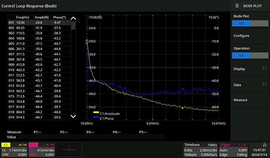
Eigenwerte ** el. EW = 0.93ms ** mech. EW = 2.93s * Bilder mit Zeitkonstante. jetzt kommt dann noch AC Betrieb. Da gibt es dann richtig Frequenz (elektrisch und mechanisch) ;-)
PA0 P0 C O D 5 C O R 2 4 C OC2COC 9 PDPD2 P0P COR 1 C O D 4 P PD2P PA1C O R 2 3 P0 P0 CO 4 O 4 O 43O 14 C O D 3 P PD2 P0P1 C O R 2 8 PR1 P0 P0 C O R 2 2 PR2 C O U 4 C O R 3 7 C O D 2 P PD2 P P1C O R 4 0 PPPPPPP1 P PA7 CO Q1 OR5 COR14 PR1 PA0 P7 PU9 PU2 PAPAP0 CO 2 CO S 2 CO S1 PR2 PA0 P7 PU1 PU2 P P1 PA21
2 e C17 3 m r=620 r=620 C4 C8 3 r 2 {cmos} R { n e 68p 4.7p C9 2 o 1 r h v {csource} R { 2 1 1 r D14 3 D 15V 1 Q13 G Q21 E E IXTP10P50P R5 R19 2 15V IXTH24N50L 1 2 B MJE350.LIB MJE350.LIB B 1 2 out 2 e 2 } S in Q7 C10 4 u 2 1 2 o D21 Q1 C 1 r=100k 2 o .paramrsource=10k C18 3 r 2 1 1 2 r=3.3k C D5 0 6 2 {csource} R { 3 .paramcsource=33p {cmos} R = 1 1 1 5 1 r D15 1 r D17 V1 15V r R R r 15V 1 Q14 + + V6 2 1 2 1 15V VSIN VSIN } IXTP10P50P y1=0 y2=7 td=400u tr=10n ac=1 D1 D8 2 c 2 dc=0 ampl=7 f=20000 td=0 theta=0 phase=0ac=1 1 2 C11 5 u 2 1 D 3.3V 3.3V {csource} R s G Q22 { D16 3 vg1 15V 1 r 15V
450W Single Output with PFC Function HRP-450 series ■ Features : User’s Manual Universal AC input / Full range Built-in active PFC function, PF>0.95 High efficiency up to 89.5% Withstand 300VAC surge input for 5 seconds Protections: Short circuit / Overload / Over voltage / Over temperature
for use in vans, small trucks, etc. • active refrigeration for food transportation • expanded 230V AC range Motor Motor type permanent magnet Speed range rpm 2000 - 4000 LRA (rated after 4 sec. UL984) HST A electronic cut-off Cut-in current HST A 6.0 Resistance, all 3 windings (25°C) Ω 14.0 Design 3
r=620 C6 MJE350.LIB B {cmos} R { n e 4.7p 1 r h v Q11 C S D G Q12 G Q19 E E IXTH10P60 R5 R18 2 e D14 IXTH24N50L 1 2 B MJE350.LIB MJE350.LIB B 1 2 out C7 9 u D 2 } S in Q7 1 s 7 o BZX84C8V2.lib Q1 C 100k {csource}R { .paramrsource=25k C14 2 r r=3.3k C 2 1 r .paramcsource=10p {cmos} R = 1 5 S 1 rBZX84C8V2
leuchtet nicht. Nichts also. Denkt man sich, das ist der einfachste Fehler. Spannung vom Netzteil (9V AC) kommt an, wird gleichgerichtet und steht mit 14V DC an den zwei dicken Elkos. Im Bild "Tel gesamt": rechts oben ist der Schalter für die Gabel / Hörer. Drunter ist die Westernbuchse für die Spannungsversorgung
Armin K. schrieb im Beitrag #7686657: > Spannung vom Netzteil (9V AC) kommt an, wird gleichgerichtet und steht > mit 14V DC an den zwei dicken Elkos. gibt es denn auch eine "plausible" Stromaufnahme, und wie hoch ist diese?
/4 193 - 200 IF Modules Supply and AF Amplifier PCB for the Two Crystal Oscillators of the 144 MHz-14 MHz MOSFET 2 m Band Converter used in DL6HA Transceiver H Kahlert, DL3YKR 1970/4 201 - 204 Oscillators PC Board for the 2 Crystal Oscillators of the 144-14 MHz MOSFET H Kahlert, DL3YKR 1970/4 201 - 204
MJE350.LIB B 1 2 out C6 8 u D 2 } S Q7 1 s 7 o BZX84C8V2.lib Q1 C r=100k {csource} { .paramrsource=50k C14 2 r r=5k C 2 1 r .paramcsource=10p {cmos} R = 1 5 S 1 rBZX84C8V2.lib R r Q12 + V5 1 G D9 v VSIN IXTH10P60 h v } D dc=0 ampl=7 f=15000 td=100u theta=0 phase=0ac=1 2 c D C7 9 u G Q18 1 1 {csource} R s
Privatkunden. Farnell hat aber zwei "Communities", die sich mit "Bastler-Projekten" befassen, Element14 und Hackster io https://community.element14.com https://www.hackster.io/ Aber von Privatkunden ist auch da nichts zu finden. Farnell gehört seit 2016 zu Avnet. https://de.farnell.com/about-us
de.wikipedia.org/wiki/Liste_prominenter_Funkamateure (da steht auch Limor Fried "ladyada" drin, die hat AC2SN) https://www.mikrocontroller.net/topic/534404 hier ein Foto der Platine https://www.eenewseurope.com/en/from-digi-keyer-to-digikey/
BC857C.lib BC857C.lib B 1 2 out 0 u D 2 } S Q7 2 s 9 o D7 bv=20 Q1 C r=100k R { .paramrsource=100k C14 2 r r=10k C 2 1 r .paramcsource=22p {cmos} R = 1 5 S 1 r bv=20 D1 R r Q11 + V5 1 G v VSIN IXTH10P60 h v } D dc=0 ampl=8 f=5000 td=100u theta=0 phase=0ac=1 2 c D 5 u G Q16 1 1 2 s vg1 R { IXTH24N50L =
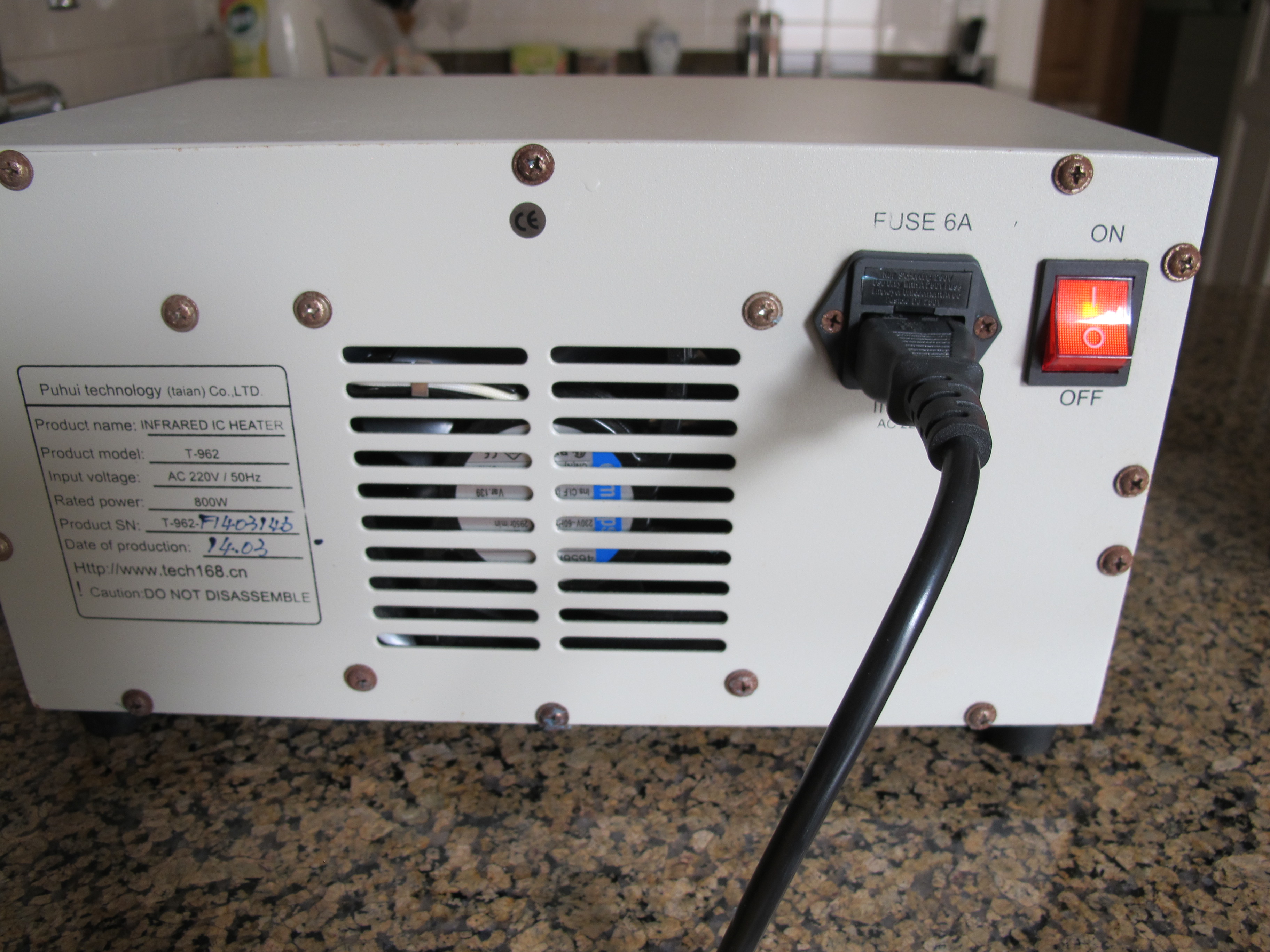
Puhui technology (taian) Co.,LTD
Product name: INFRARED IC HEATER
Product model: T-962
Input voltage: AC 220V / 50Hz
Rated power: 800W
Product SN: T-962-7403948
Date of production: 14/03
Http://www.tech168.cn
Caution: DO NOT DISASSEMBLE

 Bild
Bild
 Bild
Bild
 Bild
Bild
 Bild
Bild
 Bild
Bild
 Bild
Bild
 Bild
Bild
 Bild
Bild
 Bild
Bild
 Bild
Bild
 Bild
Bild