
-
Datei
sd_spi_stm32.c
version 2.00 */ if (send_cmd(ACMD13, 0) == 0) { /* Read SD status */ rcvr_spi(); if (rcvr_datablock(csd, 16)) { /* Read partial block */ for (n = 64 - 16; n; n--) rcvr_spi(); /* Purge trailing data */ *(DWORD*)buff = 16UL << (csd[10] >> 4); res = RES_OK; } } } else { /* SDC version 1.XX or MMC */ if ((send_cmd
in „STM32 - SPI Schnittstelle empfängt mal korrekt und dann wieder nicht“ · Mikrocontroller und Digitale Elektronik ·
-
PDF
Littelfuse_ESD_System_Level_Guide.pdf
Considerations: ● 10/100/1000 relates to the data rate in Mbps (i.e. 10Mbps, 100Mbps, and 1000Mbps) •For 10 Base-T, data is transmitted over 2 UTP (unshielded twisted pairs) using a 10MHz clock •For 100 Base-TX, data is transmitted over 2 UTP using a 125MHz clock •For 1000 Base-T data is transmitted over 4 UTP
in „Fachliteratur Entwurf Blitzductor“ · Analoge Elektronik und Schaltungstechnik ·
-
Datei
i2croutines.c
uint32_t NumbOfBytes1; __IO uint32_t NumbOfBytes2; __IO uint8_t Address; //extern unsigned char twi_buf[16]; void I2C2_changeId(unsigned char newID) { I2C_InitStructure2.I2C_OwnAddress1 = newID; } /** * @brief Configures NVIC and Vector Table base location. * @param None * @retval : None */ void NVIC_Configuration
in „stm32 Cortex I2C : Master zieht SCL auf Masse“ · Mikrocontroller und Digitale Elektronik ·
-
PDF
PSMN8R7-80PS_MOSFET.pdf
base temperature function of mounting base temperature PSMN8R7-80PS All information provided in this document is subject to lega© NXP B.V. 2010. All rights reserved. Product data sheet Rev. 02 — 1 November
in „Motoransteuerung Pi und PWM“ · Mikrocontroller und Digitale Elektronik ·
-
Datei
external_memory.c
non volatile sram on CS2 // 1 idle cycle BCFG2 &= ~(0x0000000f); // 3 wait states, 16 bit wide bus BCFG2 &= ~(0x000003e0); BCFG2 |= 0x00000460; // 3 wait states BCFG2 &= ~(0x0000f800); BCFG2 |= 0x00001800; // 16 bit bus BCFG2 &= ~(0x30000000); BCFG2 |= 0x10000000; // set up the SPC3 on
in „kann jemand mir den Fehler finden?“ · Mikrocontroller und Digitale Elektronik ·
-
Datei
external_memory.c
non volatile sram on CS2 // 1 idle cycle BCFG2 &= ~(0x0000000f); // 3 wait states, 16 bit wide bus BCFG2 &= ~(0x000003e0); BCFG2 |= 0x00000460; // 3 wait states BCFG2 &= ~(0x0000f800); BCFG2 |= 0x00001800; // 16 bit bus BCFG2 &= ~(0x30000000); BCFG2 |= 0x10000000; // set up the SPC3 on
in „external memory von lpc2294“ · Mikrocontroller und Digitale Elektronik ·
-
Datei
external_memory.c
non volatile sram on CS2 // 1 idle cycle BCFG2 &= ~(0x0000000f); // 3 wait states, 16 bit wide bus BCFG2 &= ~(0x000003e0); BCFG2 |= 0x00000460; // 3 wait states BCFG2 &= ~(0x0000f800); BCFG2 |= 0x00001800; // 16 bit bus BCFG2 &= ~(0x30000000); BCFG2 |= 0x10000000; // set up the SPC3 on
in „LPC2xxx External Memory Interface + GPIO“ · Mikrocontroller und Digitale Elektronik ·
-
Datei
readme.txt
configuration items: System Type---> ARM System Type---> [*] Philips LPC22xx [*] Set flash/sdram size and base addr (0x81000000) (S)DRAM Base Address (0x00400000) (S)DRAM Size (0x80000000) FLASH Base Address (0x00200000) FLASH Size LPC22xx options---> [ ]Default Big Endian (10000000) Oscillator Freqnecy (40000000
in „uCLinux Bootloader + Kernel für ARM LPC2294“ · Projekte & Code ·
-
PDF
SAM3X.pdf
Ltd., 2008 - 2009. 12.2 Embedded Characteristics Version 2.0 Thumb-2 (ISA) subset consisting of all base Thumb-2 instructions, 16-bit and 32-bit. Harvard processor architecture enabling simultaneous instruction fetch with data load/store. Three-stage pipeline. Single cycle 32-bit multiply. Hardware divide
in „ARM SAM3x Zähleingang“ · Mikrocontroller und Digitale Elektronik ·
-
PDF
SAM3X.pdf
Ltd., 2008 - 2009. 12.2 Embedded Characteristics Version 2.0 Thumb-2 (ISA) subset consisting of all base Thumb-2 instructions, 16-bit and 32-bit. Harvard processor architecture enabling simultaneous instruction fetch with data load/store. Three-stage pipeline. Single cycle 32-bit multiply. Hardware divide
in „Arduino Due: Programmierung ohne 16U2“ · Mikrocontroller und Digitale Elektronik ·
-
Datei
Vivaz_Pro.txt
.bin G:\RESOURCE\FONT\FT16.bin G:\RESOURCE\FONT\FT24.bin G:\RESOURCE\LANGUAGE G:\RESOURCE\LANGUAGE\CHINESE G:\RESOURCE\LANGUAGE\CHINESE\GBK2U.BIN G:\RESOURCE\LANGUAGE\CHINESE\OUFT12.BIN G:\RESOURCE\LANGUAGE\CHINESE\OUFT16.BIN
in „Handydummy (Attrappe)mit richtigem Display - Sony Ericsson Vivaz“ · Mikrocontroller und Digitale Elektronik ·
-
PDF
AN1040-D.PDF
first has insulation between the Measured Thermal Resistance semiconductor chips and the mounting base; an exposed area of the mounting base is used to secure the part. The (⋅C/W) Thermalloy Bergquist Energy Management Series (EMS) modules, shown in Material Data (1) Data (2) Figure 16, Case 806 (ICePAK
in „Welches Transistorgehäuse ist am besten zu kühlen?“ · Mikrocontroller und Digitale Elektronik ·
-
PDF
AN1040-D.PDF
first has insulation between the Measured Thermal Resistance semiconductor chips and the mounting base; an exposed area of the mounting base is used to secure the part. The (⋅C/W) Thermalloy Bergquist Energy Management Series (EMS) modules, shown in Material Data (1) Data (2) Figure 16, Case 806 (ICePAK
in „Wärmewiderstand Rthg - Rthgk“ · Analoge Elektronik und Schaltungstechnik ·
-
PDF
AN1040-D.PDF
first has insulation between the Measured Thermal Resistance semiconductor chips and the mounting base; an exposed area of the mounting base is used to secure the part. The (⋅C/W) Thermalloy Bergquist Energy Management Series (EMS) modules, shown in Material Data (1) Data (2) Figure 16, Case 806 (ICePAK
in „Gibt es Alternativen zu Silikonpads?“ · Mikrocontroller und Digitale Elektronik ·
-
PDF
AN1040-D.pdf
first has insulation between the Measured Thermal Resistance semiconductor chips and the mounting base; an exposed area of the mounting base is used to secure the part. The (⋅C/W) Thermalloy Bergquist Energy Management Series (EMS) modules, shown in Material Data (1) Data (2) Figure 16, Case 806 (ICePAK
in „Kurzschluss durch Kühlörper?“ · Analoge Elektronik und Schaltungstechnik ·
-
PDF
AN1040-D.PDF
first has insulation between the Measured Thermal Resistance semiconductor chips and the mounting base; an exposed area of the mounting base is used to secure the part. The (⋅C/W) Thermalloy Bergquist Energy Management Series (EMS) modules, shown in Material Data (1) Data (2) Figure 16, Case 806 (ICePAK
in „Reicht das Eloxal als Isolierung?“ · Mechanik, Gehäuse, Werkzeug ·
-
PDF
AN1040-D.pdf
first has insulation between the Measured Thermal Resistance semiconductor chips and the mounting base; an exposed area of the mounting base is used to secure the part. The (⋅C/W) Thermalloy Bergquist Energy Management Series (EMS) modules, shown in Material Data (1) Data (2) Figure 16, Case 806 (ICePAK
in „MOSFET Power Dissipation“ · Analoge Elektronik und Schaltungstechnik ·
-
PDF
IntegratedMagneticsBo.pdf
structure B Fig.18 Equivalent-circuit for mode (a) In this circuit, Lr, Lm and Na are given by the Base on the electrical structure, there are two possible connections of the primary windings. Fig.16 shows one following equations: connection method, which connects the dot-marked L1⋅L0 terminal with unmarked
in „Trafo: Streuinduktivität für LCC Regler berechnen“ · Analoge Elektronik und Schaltungstechnik ·
-
Datei
t6963c_main_v1.asm
kurz warten sbi PortB,reset ; Reset auf H rcall delay ; text start adress set ldi daten,low (TXT_BASE) rcall WriteByte ldi daten,high(TXT_BASE) rcall WriteByte ldi command, (TXTHOME) rcall WriteCMD ; text area adress set ldi daten, (SPALTEN) rcall WriteByte ldi daten, 0x00 rcall WriteByte ldi command
-
Datei
FT800_commands.c
>> 8)); spi_transmit((uint8_t)(color >> 16)); spi_transmit(0x00); ft800_cs_clear(); ft800_inc_cmdoffset(4); } void ft800_cmd_gauge(int16_t x0, int16_t y0, int16_t r0, uint16_t options, uint16_t major, uint16_t minor, uint16_t val, uint16_t range
-
Datei
FT800_commands.c
spi_transmit((uint8_t)(rgb1 >> 8)); spi_transmit((uint8_t)(rgb1 >> 16)); spi_transmit(0x00); ft800_cs_clear(); ft800_inc_cmdoffset(16); // update the command-ram pointer } void ft800_cmd_keys(int16_t x0, int16_t y0, int16_t w0, int16_t h0, int16_t font, uint16_t options
-
PDF
Interfacing_the_Serial_RS232_Port.pdf
micro-channel bus, then expect a different set of addresses and IRQ's. Just like the LPT ports, the base addresses for the COM ports can be read from the BIOS Data Area. Start Address Function 0000:0400 COM1's Base Address 0000:0402 COM2's Base Address 0000:0404 COM3's Base Address 0000:0406 COM4's Base
in „fehlerfreie UART-Übertragung?“ · Mikrocontroller und Digitale Elektronik ·
-
Datei
configx.h
\ur_org\stack.c.h" //#include "C:\winAVRkk\avr2015\500 web radig\stack.c" #include "C:\zuc\ur_org\base64.h" #include "C:\zuc\ur_org\base64.c.h" #include <C:\zuc\ur_org\httpd.h> #include "C:\zuc\ur_org\webpage.h" #include <C:\zuc\ur_org\httpd.c.h> #endif #if 0 #if zucAVR==0 #include "C:\zuc\net\wkkstring.h
in „Header Datei für Konfiguration erstellen“ · Mikrocontroller und Digitale Elektronik ·
-
Datei
ff.h
API */ #ifndef _INC_TCHAR #define _INC_TCHAR #if FF_USE_LFN && FF_LFN_UNICODE == 1 /* Unicode in UTF-16 encoding */ typedef WCHAR TCHAR; #define _T(x) L ## x #define _TEXT(x) L ## x #elif FF_USE_LFN && FF_LFN_UNICODE == 2 /* Unicode in UTF-8 encoding */ typedef char TCHAR; #define _T(x) u8 ## x #define
in „Arduino Sloeber - C Code einbinden“ · Mikrocontroller und Digitale Elektronik ·
-
Datei
mac.c
==========================================*/ { tDWord dwIdx; tpDWord pdwRxDesc = (tpDWord)RX_DESC_BASE; /* rx descriptors are in eth ram */ RxDescriptor = RX_DESC_BASE; for(dwIdx = 0; dwIdx < MAC_RX_FRAGMENTS; dwIdx++) { *pdwRxDesc = (tDWord)&bRxBuffer[dwIdx * ETH_FRAG_SIZE]; /* packet */ pdwRxDesc++
in „IP-Stack bauen“ · Mikrocontroller und Digitale Elektronik ·
-
Datei
main.c
define HITEX_BOARD 1 /* 0 is NXP SJA2510 board */ #if HITEX_BOARD #define PLL_M_VALUE (10-1) /* OSC is 16Mhz, multiplier is 10 */ #else #define PLL_M_VALUE (16-1) /* OSC is 10Mhz, multiplier is 16 */ #endif /* The ring osc is 400Khz. The CCO clock is always 160Mhz, the Post divider is always 2. So, the CPU_CLK
in „Starthilfe für LPC2919 mit KEIL und J-LINK EDU“ · Mikrocontroller und Digitale Elektronik ·
-
Datei
communication.c
USART1 transmission RCC_AHBPeriphClockCmd(RCC_AHBPeriph_DMA1, ENABLE); DMA_InitStructure.DMA_PeripheralBaseAddr = 0x40013804; DMA_InitStructure.DMA_MemoryBaseAddr = (uint32_t)transmissionBuffer.buffer; DMA_InitStructure.DMA_DIR = DMA_DIR_PeripheralDST; DMA_InitStructure.DMA_BufferSize = 0; DMA_InitStructure.DMA_PeripheralInc
in „STM32 DMA aktivieren in USART-Interrupt -> Byte doppelt“ · Mikrocontroller und Digitale Elektronik ·
-
Datei
ch557.h
Registers */ #define ROM_PAGE_SIZE 0x40 // FlashROM page size ( number of bytes ) #ifndef __UC__ SFR16_(ROM_ADDR, 0x84); // address for flash-ROM, little-endian SFR16_(ROM_DATA_LO,0x84); // ReadOnly: low word data (16 bits) for flash-ROM reading, little-endian SFR16_(ROM_DATA_HI,0x8E); // ReadOnly: high
in „uC für 0,20€ CH552 / CH554 von WCH Billig Micro mit USB Funktion, Chip vorstellung“ · Mikrocontroller und Digitale Elektronik ·
-
PDF
uln2803a.pdf
2017 5 Pin Configuration and Functions DW Package 18-Pin SOIC Top View 1B 1 18 1C 2B 2 17 2C 3B 3 16 3C 4B 4 15 4C 5B 5 14 5C 6B 6 13 6C 7B 7 12 7C 8B 8 11 8C GND 9 10 COM Not to scale Pin Functions PIN TYPE DESCRIPTION NAME NO. 1B 1 2B 2 3B 3 4B 4 I Channel 1 through 8 Darlington base input 5B 5 6B
in „PCB Komponenten zur Ansteuerung von Wasserpumpen (Anfänger)“ · Analoge Elektronik und Schaltungstechnik ·
-
Datei
u-boot.cfg.txt
#define CONFIG_SYS_SDRAM_BASE 0x80000000 #define CONFIG_IMAGE_FORMAT_LEGACY 1 #define CONFIG_ARCH_MISC_INIT 1 #define CONFIG_SYS_BOOT_RAMDISK_HIGH #define CONFIG_MMC_VERBOSE 1 #define CONFIG_NET_TFTP_VARS 1 #define CONFIG_MKIMAGE_DTC_PATH
in „Linux Kernel 5.1.1. auf dem BPi-R2“ · PC Hard- und Software ·
-
PDF
BD330.PDF
Absolute Maximum Rating System (IEC 134). SYMBOL PARAMETER CONDITIONS MIN. MAX. UNIT VCBO collector-base voltage open emitter − −32 V VCEO collector-emitter voltage open base − −20 V V emitter-base voltage open collector − −5 V EBO C collector current (DC) − −3 A CM peak collector current − −3 A BM peak base current − −1 A Ptot total power dissipation T mb≤ 45 °C − 15 W T storage temperature −65 +150 °C stg Tj junction temperature − 150 °C Tamb operating ambient temperature −65 +150 °C 1999 Apr 26 2 Philips
-
Datei
dmesg_complete.txt
, assigned bus number 3 [ 1.140047] uhci_hcd 0000:00:1a.0: irq 16, io base 0x0000bc00 [ 1.140156] hub 3-0:1.0: USB hub found [ 1.140160] hub 3-0:1.0: 2 ports detected [ 1.140223] uhci_hcd 0000:00:1a.1: PCI INT B -> GSI 21 (level, low) -> IRQ 21 [ 1.140229] uhci_hcd
in „Pollin - Receiver-Mainboard mit Twin DVB-[T,C] Tuner, NXP PNX8950EH“ · Mikrocontroller und Digitale Elektronik ·
-
Datei
log.txt
_) | |_ \___/ |____/ \___/ \___/ \__| ** MARVELL BOARD: SHEEVA PLUG LE U-Boot 1.1.4 (Jul 19 2009 - 16:03:28) Marvell version: 3.4.19 U-Boot code: 00600000 -> 0067FFF0 BSS: -> 006CFB00 Soc: 88F6281 A0 (DDR2) CPU running @ 1200Mhz L2 running @ 400Mhz SysClock = 400Mhz , TClock = 200Mhz DRAM CAS Latency = 5 tRP = 5 tRAS = 18 tRCD=6 DRAM CS[0] base 0x00000000 size 256MB DRAM CS[1] base 0x10000000 size 256MB DRAM Total size 512MB 16bit width Addresses 8M - 0M are saved for the U-Boot usage. Mem malloc Initialization (8M - 7M): Done NAND:256 MB
in „20Euro Embedded System mit ARM, 128MB ram und 256MB Flash“ · Mikrocontroller und Digitale Elektronik ·
-
Datei
ohne_kontrollausgabe.asm
8e 01 movw r16, r28 302: 0f 5d subi r16, 0xDF ; 223 304: 1f 4f sbci r17, 0xFF ; 255 do { char c = n % base; 306: 84 2e mov r8, r20 308: 91 2c mov r9, r1 30a: b1 2c mov r11, r1 30c: a1 2c mov r10, r1 30e: a5 01 movw
in „AVR Inline Optimierung kaputt?“ · Mikrocontroller und Digitale Elektronik ·
-
Datei
main.c
_DMA_Channel, DISABLE); //Read Accel data from byte 0 to byte 2 for(i=0; i<3; i++) AccelGyro[i]=((s16)((u16)I2C_Rx_Buffer[2*i] << 8) + I2C_Rx_Buffer[2*i+1]); //Skip byte 3 of temperature data //Read Gyro data from byte 4 to byte 6 for(i=4; i<7; i++) AccelGyro[i-1]=((s16)((u16)I2C_Rx_Buffer[2*i] << 8)
in „STM32F103 + I2C + MPU6050 - DMA“ · Mikrocontroller und Digitale Elektronik ·
-
PDF
AV02-1132EN_DS_HEDS-9x40_2014-03-17__3_.pdf
ALIGNINGRECESS (0.096/0.095) 1.85(0.073) CL HOLE2PLACES 1.78±0.10* 5.46±0.10 2.44/2.41X2.79 ALIGNINGRECESS 2.16(0.085) (0.070±0.004) (0.215±0.004) (0.096/0.095X0.110) 2.44/2.41DIA. DEEP 8.64(0.340) 2.44/2.41X2.79 2.16(0.085)DEEP (0.096/0.095) REF. 17.27 (0.096/0.095X0.110) 2.92±0.10** 2.16(0.085)DEEP (0.680) 2.16
in „Incremental Encoder läuft nicht an 2 µC“ · Mikrocontroller und Digitale Elektronik ·
-
 Bild
Bild
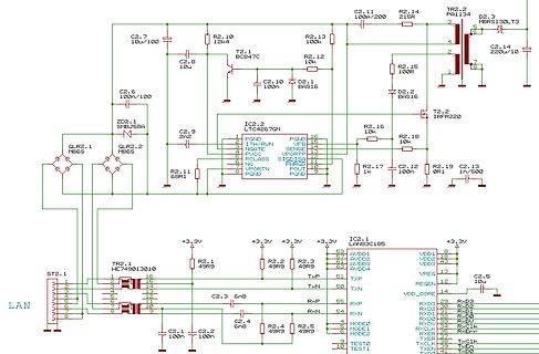
Schaltplan eines LAN-Moduls mit LTC4267QN
T2.1 BCS47C R2.13 100k C2.11 100p/200 R2.14 215R TR2.2 MBRS13OLT3D2.3 C2.14 220u/10 R2.15 100R D2.2 BAS16 T2.2 IRFR220 C2.10 100n D2.1 BAS16 C2.6 100n/100 ZD2.1 SMBJ5A C2.9 2n2 IC2 LTC4267QN QLR2.1 MB6S QLR2.2 MB6S R2.11 6R1 R2.16 10k R2.18 10k R2.17 1k C2.12 100n R2.19 0R C2.13 1n/500 ST2.1 WE749013010
in „Frage zu PoE Transformer“ · Analoge Elektronik und Schaltungstechnik · · Schaltpläne
-
Datei
strace.txt
=0, msg_flags=0}, 0) = 20 sendto(4, {{len=20, type=0x16 /* NLMSG_??? */, flags=NLM_F_REQUEST|0x300, seq=1555679995, pid=0}, "\0\0\0\0"}, 20, 0, {sa_family=AF_NETLINK, nl_pid=0, nl_groups=00000000}, 12) = 20 recvmsg(4, {msg_name={sa_family=AF_NETLINK, nl_pid
-
Datei
rtmp_def.h
EAPOL Key descripter frame format related length #define LEN_KEY_DESC_NONCE 32 #define LEN_KEY_DESC_IV 16 #define LEN_KEY_DESC_RSC 8 #define LEN_KEY_DESC_ID 8 #define LEN_KEY_DESC_REPLAY 8 #define LEN_KEY_DESC_MIC 16 #define LEN_MASTER_KEY 32 // EAPOL EK, MK #define LEN_EAP_EK 16 #define LEN_EAP_MICK 16
in „Pollin MOTOROLA VIP1710“ · Mikrocontroller und Digitale Elektronik ·
-
Datei
ebi_driver.h
interfaceMode ); void EBI_EnableSRAM( volatile EBI_CS_t * chipSelect, EBI_CS_ASPACE_t addrSpace, uint32_t baseAddr, uint8_t waitStateCycles ); void EBI_EnableLPC( volatile EBI_CS_t * chipSelect, EBI_CS_ASPACE_t addrSpace, uint32_t baseAddr, uint8_t waitStateCycles ); void EBI_EnableSDRAM( EBI_CS_ASPACE_t addrSpace
in „SDRAM und Xmeaga-A X-Plained“ · Mikrocontroller und Digitale Elektronik ·
-
Datei
ebi_driver.h
interfaceMode ); void EBI_EnableSRAM( volatile EBI_CS_t * chipSelect, EBI_CS_ASPACE_t addrSpace, uint32_t baseAddr, uint8_t waitStateCycles ); void EBI_EnableLPC( volatile EBI_CS_t * chipSelect, EBI_CS_ASPACE_t addrSpace, uint32_t baseAddr, uint8_t waitStateCycles ); void EBI_EnableSDRAM( EBI_CS_ASPACE_t addrSpace
in „Viel RAM am kleinen Controller“ · Mikrocontroller und Digitale Elektronik ·
-
PDF
4N38.pdf
1 minute - 7500 VAC PEAK - 1 minute Underwriters Laboratory (UL) recognized File# E90700 ANODE 1 6BASE APPLICATIONS CATHOD2 5COLLECTOR Power supply regulators Digital logic inputs N/C3 4EMITTER Microprocessor inputs Appliance sensor systems Industrial controls ABSOLUTE MAXIMUM RATINGS Parameter Symbol
in „A4N38 Optokoppler SMD Gehäuse ?“ · Mikrocontroller und Digitale Elektronik ·
-
Datei
Pg33_38_a.txt
par le but. Rrmarque. — La ligne de visée O B détermine avec la verticale O O/ l'angle de tir (fig. 16). La ligne de visée O O/ (verticale) n’est pas matéria- lisée sur le viseur S. T. Aé, O A est la ligne de visée d’impact. 2° Réglage de la ligne de visée par mesure de vitesse préliminaire. Réglage du
-
Datei
kk_dcmi.h
DCMI_PCKPolarity_Rising //#define pclk_polarity DCMI_PCKPolarity_Falling #define sccb_bus_wr sccb_wr_16_8 #define sccb_bus_rd sccb_rd_16_8 #define cam_format_xQVGA 3 #define reg_datei ov3640_reg #define regDateiFile "ov3640_regs.h" #endif #if cam_chip==cam_mtd112//not tested #define cam_adr 0xba #define
in „stm32f429 Expansion board“ · Mikrocontroller und Digitale Elektronik ·
-
PDF
MAX9271.pdf
slave device received it, or that an error occurred during the response from the slave device. In base mode, the and the ACK byte (0xC3). The FC and the connected FC must keep the UART Tx/Rx lines high for 16 bit times slave chip generate the SYNC byte and ACK byte, respectively. Events such as device
-
 Bild
Bild
Tabelle der Übertragungsfrequenzen für verschiedene Dienste
over ISDN G.992.1 Annex B ADSL 2+ VDSL 2 [Mbit/s] 50 100 Ethernet [Mbit/s] 10 100 1 000 10 000 10BASE-T 100BASE-TX 1000BASE-X 10GBASE-T 0,3...3,4 kHz 16 kHz 0...120 kHz 8...96 kHz 138...1104 kHz 138...2208 kHz 17,7 MHz 30 MHz 10 MHz 31,25 MHz 62,5 MHz 416,7 MHz
in „HD-SDI ueber twisted pair“ · HF, Funk und Felder · · Screenshots

-
PDF
Testtool.pdf
unter Windows mit dem Hyperterminal ausgelesen werden. Einstellungen von Hyperterminal: Die Testtool.bas kann zum Beispiel mit Bascom AVR geöffnet und verändert werden. Das Programm wurde für den Atmega 16 geschrieben, kann aber für jeden anderen, Pinkompatiblen Mikrocontroller geändert werden ( nur die
in „Probleme mit Atmel Evaluationsboard V2.0“ · Mikrocontroller und Digitale Elektronik ·
-
PDF
Testtool.pdf
unter Windows mit dem Hyperterminal ausgelesen werden. Einstellungen von Hyperterminal: Die Testtool.bas kann zum Beispiel mit Bascom AVR geöffnet und verändert werden. Das Programm wurde für den Atmega 16 geschrieben, kann aber für jeden anderen, Pinkompatiblen Mikrocontroller geändert werden ( nur die
in „PonyProg2000 "Device missing"“ · Mikrocontroller und Digitale Elektronik ·
-
PDF
Testtool.pdf
unter Windows mit dem Hyperterminal ausgelesen werden. Einstellungen von Hyperterminal: Die Testtool.bas kann zum Beispiel mit Bascom AVR geöffnet und verändert werden. Das Programm wurde für den Atmega 16 geschrieben, kann aber für jeden anderen, Pinkompatiblen Mikrocontroller geändert werden ( nur die
in „Pollin Funk-AVR-Board + ATMega8 - Einstieg“ · Mikrocontroller und Digitale Elektronik ·
-
PDF
PWM-Halbbruecke_Sch.pdf
PAD1 C221 C222 D11 P1 STL1550 2 1 Stift1 ~9 100n 22u16V 1 M11 8 +5V BAS40-043 2 D 7 P1 STL1550 3 6 ~10 1 HS_gnd HS_10V R121 4 5 in R11 G S T213 T214 10R U2C U2D 4.7k 1 IRF7855 9 12 T6 1 U11 8 R13 R5 8 R6 11 Vcc Vb P1 STL1550 1 10 & 1 13 & 2 in HO 7 10k ~
in „Motoransteuerung - 24vdc / max. 500W“ · Analoge Elektronik und Schaltungstechnik ·

