-
PDF
JuCanSchematic.pdf
SENSOR_VP IO22 23 1 1 5 SENSOR_VN TXD0 24 2 +VIN 6 IO34 RXD0 25 3 GND 7 IO35 IO21 26 +VOUT LED2 IO32 GND2 GND GND LED3 8 IO33 IO19 27 SPI_MISO LED1 9 IO25 IO18 28 SPI_SCK 10 IO26 IO5 29 SPI_CS 11 IO27 IO17 30 SPI_INT 5 + C4 12 IO14 IO16 31 + 13 32 10uF GND 14 IO12 IO4 33 15 GND1 IO0 34 16 IO13 IO2 35 17 SD2 IO15 36 T_DATA GND TP2 TP1 SD3 SD1 18 CMD SD0 37 +5V 19 EXT_5V CLK 38 ESP32-DEVKITC-32D Header: 691313510004 Plug: 691351500004 CAN_P 1 1 CAN_N 2 2 GND 3 3 IC3 VIN 4 4 GND TJA1050T-CM/118 J1 1 8 N CAN_P 691313510004 2 TXD S 7 G JP2 3 GND CANH 6 CAN_N VIN 1 4 VCC CANL 5 2
-
Datei
benchmark.py
int = size//2 while (idx:=idx-1) >= 0: dest[idx] = src[idx] @micropython.viper def memcpyW(src: ptr32, dest: ptr32, size:int): idx: int = size//4 while (idx:=idx-1) >= 0: dest[idx] = src[idx] def test(): cpufreq(240*MEG) t0 = ticks_us() ba1 = bytearray(SIZE) ba2 = bytearray(SIZE) t1 = ticks_us() memcpyB
-
Bild
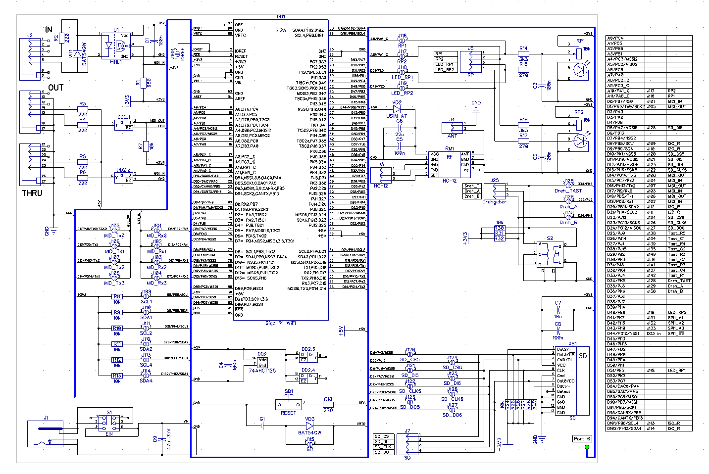
Schaltplan einer Elektronikschaltung mit Mikrocontroller
DD1 ESP32, DO, D1, D2, D3, D4, D5, D6, D7, D8, D9, D10, D11, D12, D13, D14, D15, D18, D19, D21, D22, D23, D25, D26, D27, D32, D33, GPIO, SDA, SCL, RESET, GND, 3V3, 5V, LED1, LED2, LED3, LED4, R1, R2, R3, R4
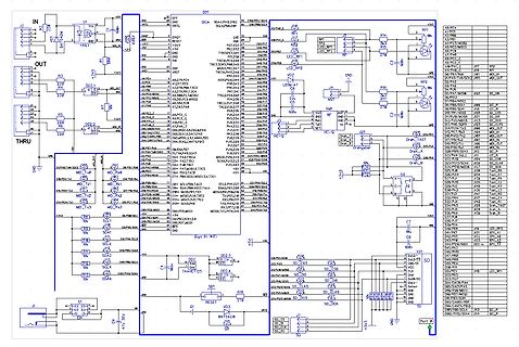
in „I2C Display einfache Frage“ · Mikrocontroller und Digitale Elektronik · · Schaltpläne
-
Datei
memcopy2.py
KILO) # max. for RP2040 SIZE = const(242*KILO) # max. for RP2350 # SIZE = const(900*KILO) # ~ for an ESP with 2MiB PSRAM @micropython.viper def memcpyB(src: ptr8, dest: ptr8, size:int): idx: int = size while (idx:=idx-1) >= 0: dest[idx] = src[idx] @micropython.viper def memcpyHW(src: ptr16, dest: ptr16
-
Bild
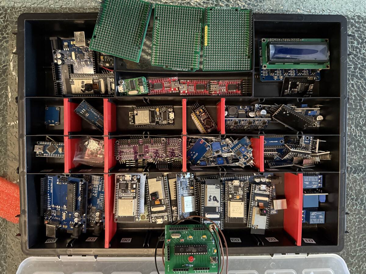
Sortiment an Mikrocontrollern und Leiterplatten in einer Kunststoffbox
Arduino, ATmega, ESP32, STM32, LCD
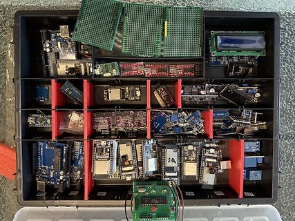
in „(V) elektronische Bauelemente“ · Markt · · Fotos
-
Bild
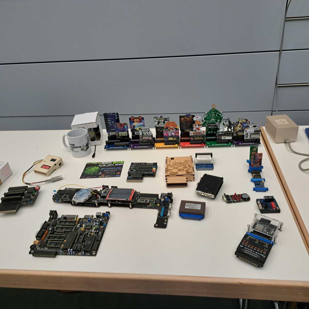
Sammlung verschiedener Mikrocontroller-Boards und Elektronikkomponenten
Arduino, Raspberry Pi, ESP32, STM32, ATmega
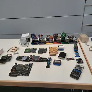
in „Veranstaltungstipp: Retro-Computing Treffen 2025“ · Offtopic · · Fotos
-
Bild
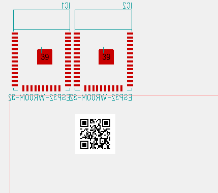
Ausschnitt eines PCB-Layouts mit QR-Code
IC1 IC2 39 39 ESP32-WROOM-32E
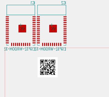
in „Target 3001 V32 – GUI-Verbesserungen, Import und Export“ · Platinen · · Layouts
-
Bild
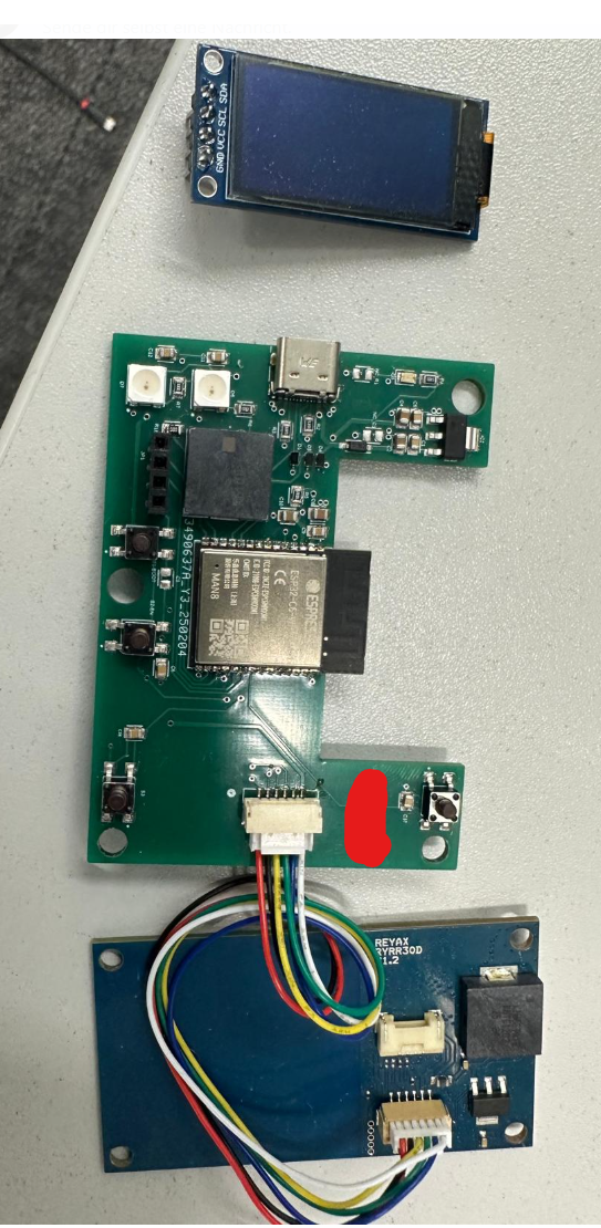
Leiterplatten mit Display und Verkabelung
680B CC5L SDA ESP32-WROOM-32 REYAX RYR30D 1.2
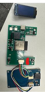
in „EMV /RED-Albtraum bei NFC-Reader (ESP32) – Maschinenbauer brauchen dringend E-Technik/EMV-Rat!“ · HF, Funk und Felder · · Platinenfotos
-
Bild
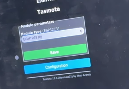
Tasmota Webinterface Modulparameter-Einstellungen
Tasmota Module parameters Module type (ESP32C3) EIGHTREE (0) Save Configuration Tasmota 13.3.0(tasmota32) by Theo Arends
in „Tasmota ESP32C3 Fast keine Reaktion nach Firmwareupdate“ · Haus & Smart Home · · Fotos
-
Bild
Zwei Männer in einem Videocall mit eingeblendeter Frage
LIVE Question Will there be improvements for the SDK Config, to compete with STM32's Cube IDE and make configuration for ESP32 easier?
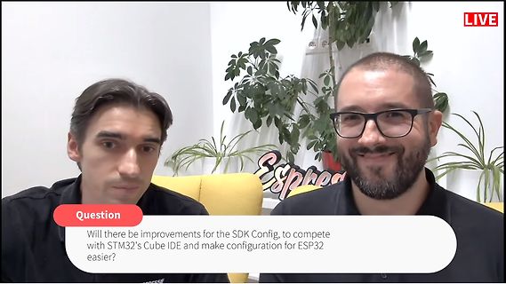
in „Espressif DevCon 2023, Tag 2 – Das Ökosystem spricht“ · Mikrocontroller und Digitale Elektronik · · Fotos
-
Bild
Zwei schwarze Leiterplatten auf Holzuntergrund
BOOT, EN, VT 25V 1000, POWER, 3266296PLB9-240315, LED 0.42, X, Y, ESP32-WROOM-32E, CE, MOTOR1, MOTOR2, LIGHT
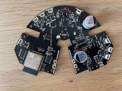
in „Es wird nur ein I2C Gerät erkannt“ · Mikrocontroller und Digitale Elektronik · · Platinenfotos
-
Bild
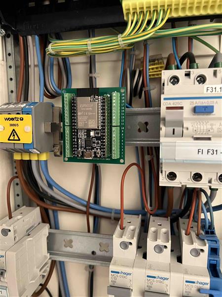
Elektroverteiler mit Mikrocontroller-Modul und Sicherungsautomaten
woertz 3886/5 ESP32-WROOM-32 F31.1 CDA 4250 FI F31-1 MCS :hager MCS 013C MCS 013C MCS 013C
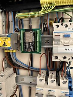
in „ESP32 Shield“ · Mikrocontroller und Digitale Elektronik · · Fotos
-
PDF
Last_board_mixed.pdf
I-NOTAUS_4 INPUT-OC-ALARM-IN-4 CURRENT_4 OVCURRENT_I_IN_4 3 3 OVERCURRENT-PROTEKTION1 +3V3 + PIC-ALARM-IN ESP_ALARM ESP-ALARM-IN DGND 3 V DGND + +3V3 DGND DGND E E Übersicht Übersicht Last_board 09.05.2020 22:37 Sheet: 1/1 1 2 3 4 5 6 7 8 09.05.2020 22:52 D:\Arbeit\Git\E-Last\03_Schaltplan\01_Eagle\Last_board.sch
in „Schaltplankontrolle Last- + HMI-Board“ · Mikrocontroller und Digitale Elektronik ·
-
Bild
Header eines Mikrocontroller- und Digital-Elektronik-Forums
Suchen | Einstellungen | Benutzerliste | Bildergalerie | Hilfe | Logout Filter: ARM AVR Arduino MSP430 ESP PIC 8051 AVR32 C16x PowerPC R8C/M16C/M32C Keine Beiträge gefunden.
in „Threads werden nach einloggen nicht mehr angezeigt“ · www.mikrocontroller.net · · Screenshots
-
Bild
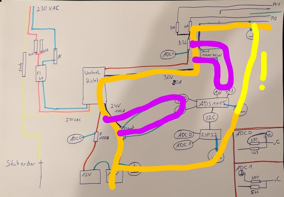
Handgezeichneter Schaltplan mit farbigen Markierungen
230 VAC PV1 PV2 B16 B32 Short 100A 75mV ADC1 Wechsel Richt 30V 80A A2 A3 ADS1115 12C ADC0 ESP32 ADC0 680 UC 12V 100A ADC1 5k6 6 ADC0 F 10A Stabederd
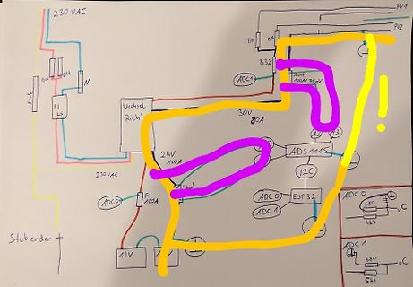
in „OPV für Shunt-Messung (100A)“ · Analoge Elektronik und Schaltungstechnik · · Fotos
-
Bild
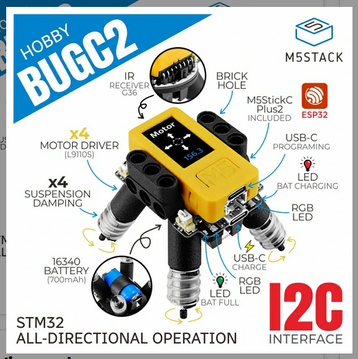
Produktgrafik eines M5Stack BUGC2 Roboter-Bausatzes
HOBBY BUGC2 M5STACK IR RECEIVER G36 BRICK HOLE M5StickC Plus2 INCLUDED ESP32 USB-C PROGRAMING x4 MOTOR DRIVER (L9110S) x4 SUSPENSION DAMPING USB-C CHARGE RGB LED LED BAT CHARGING 16340 BATTERY (700mAh) RGB LED USB-C CHARGE LED BAT FULL I2C INTERFACE STM32 ALL-DIRECTIONAL OPERATION
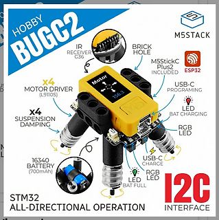
in „Bauteil-News: Entwicklerboards, Elektromechanik und vieles andere mehr“ · Mikrocontroller und Digitale Elektronik · · Screenshots
-
Bild
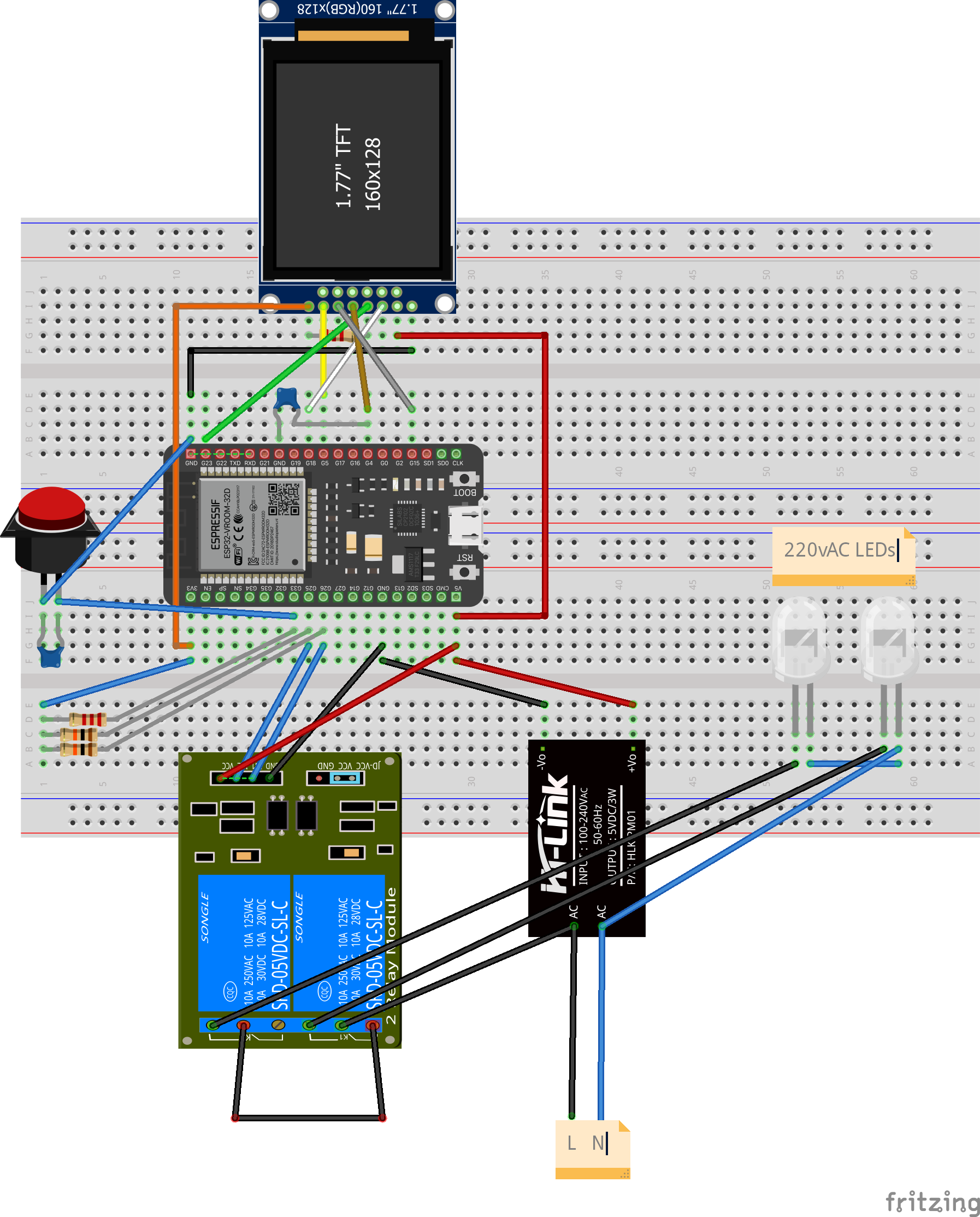
Fritzing-Simulation eines Mikrocontroller-Aufbaus auf Breadboard
1.77" TFT 160x128 ESPRESSIF ESP32-WROOM-32 BOOT RST 220VAC LEDs SONGLE SI-P05DVC5LC-L SI-P05DVC5LC-W 10A 250VAC 10A 250VAC 10A 250VAC 10A 250VAC W 30V AC 10A 250VAC K-Link INPUT 100-240VAC 50/60Hz AC L N
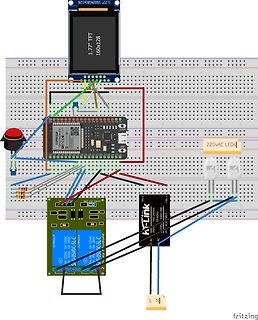
in „220V Leds Stören esp32“ · Mikrocontroller und Digitale Elektronik · · Screenshots
-
Bild
Header eines deutschsprachigen Elektronik-Forums
EmbDev.net eingeblendet (Info). Englischsprachige Beiträge ausblenden Filter: ARM AVR Arduino MSP430 ESP PIC 8051 AVR32 C16x PowerPC R8C/M16C/M32C [keiner] Im Betreff suchen
in „Seltsamer Link zu embdev.net“ · www.mikrocontroller.net · · Screenshots
-
Bild
Diagramm zur Hardware-Architektur-Nutzung für eingeschränkte Geräte
Hardware Architecture Usage for Constrained Devices 2024 2023 ARM Cortex-M3/M4 36% 33% ARM Cortex-M0/M0+ 32% 33% ESP32 (Tensilica Xtensa) 28% 22% RISC-V Architectures 13% 7% Q: What hardware architecture(s) do you use for Constrained Devices? (Select up to three) COPYRIGHT (C) 2024, ECLIPSE FOUNDATION, INC
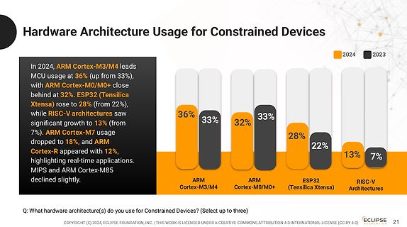
in „Eclipse-Entwicklerumfrage, MicroPython und Arduino-Cores auf Basis von Zephyr“ · Mikrocontroller und Digitale Elektronik · · Diagramme
-
PDF
raffstorecontrol.pdf
1 2 3 4 5 6 Input GND Display und Steuerung U5 - PullUps ESP intern ULN2803A - Logik high mit 24V 128x64px C4 3 10 Q1 SDA 1 SSD1315 3 COM 2N7002 SCL 2 1,3 inch OLED 100nF 1 I1 O1 18 1 GND J5 U9 2 17 2 2 3 3 Conn_01x04 GND U8 I2 O2 3.3V 4 PC817 9 MCP23017 3 I3
in „mcp23017 pull up / Vorwiderstand erforderlich?“ · Mikrocontroller und Digitale Elektronik ·
-
PDF
raffstorecontrol.pdf
1 2 3 4 5 6 Input 24V Display und Steuerung U5 - PullUps ESP intern ULN2803A - Logik high mit 24V 128x64px C4 3 10 SDA 1 SSD1315 3 COM SCL 2 1,3 inch OLED 100nF 1 I1 O1 18 1 GND J5 U9 2 17 2 3 Conn_01x04 GND U8 I2 O2 3.3V 4 PC817 9 MCP23017 3 I3 O3 16 3 1 4 4
in „mcp23017 pull up / Vorwiderstand erforderlich?“ · Mikrocontroller und Digitale Elektronik ·
-
Bild
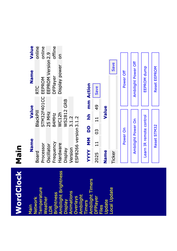
Software-Menü für WordClock Projekt
Overlays Ambilight Timers DFPlayer Files Update Local Update Main Name Value RTC online Processor STM32F401CC EEPROM online Oscillator 25 MHz 84MHz Hardware WS2812 GRB Display 3.1.2 Version ESP8266 version 3.1.2 YYYY MM DD hh mm Action 2025 11 03 11 49 Save Ticker Power On Ambilight Power On Learn IR remote control Power Off Ambilight Power Off EEPROM dump Reset STM32 Reset EEPROM
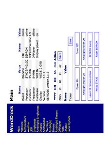
in „WordClock mit WS2812“ · Projekte & Code · · Screenshots
-
Bild
Webinterface einer WordClock mit Systemstatus und Einstellungen
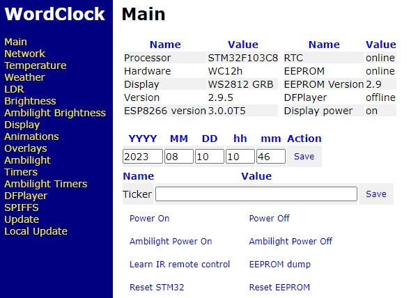
WordClock Main Main Name Value Name Value Processor STM32F103C8 RTC online Hardware WC12h EEPROM online Display WS2812 GRB EEPROM Version 2.9 Version 2.9.5 DFPlayer offline ESP8266 version 3.0.0T5 Display power on YYYY MM DD hh mm Action 2023 08 10 10 46 Save
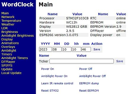
in „WordClock mit WS2812“ · Projekte & Code · · Screenshots
-
Bild
C++ Code und Serieller Monitor Ausgabe
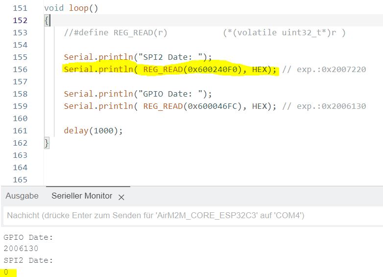
151 void loop() 152 { 153 //#define REG_READ(r) (*(volatile uint32_t*)r ) 154 Serial.println("SPI2 Date: "); 155 Serial.println( REG_READ(0x600240F0), HEX); // exp.:0x2007220 157 Serial.println("GPIO Date: "); 159 Serial.println( REG_READ(0x600046FC), HEX); // exp.:
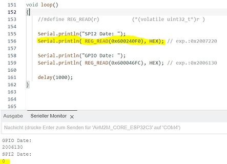
in „ESP32C3 SPI2 Controller Register lesen fehlerhaft“ · Mikrocontroller und Digitale Elektronik · · Screenshots
-
Bild
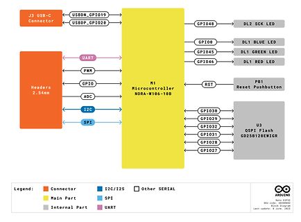
Blockdiagramm der NORA-W10 Serie
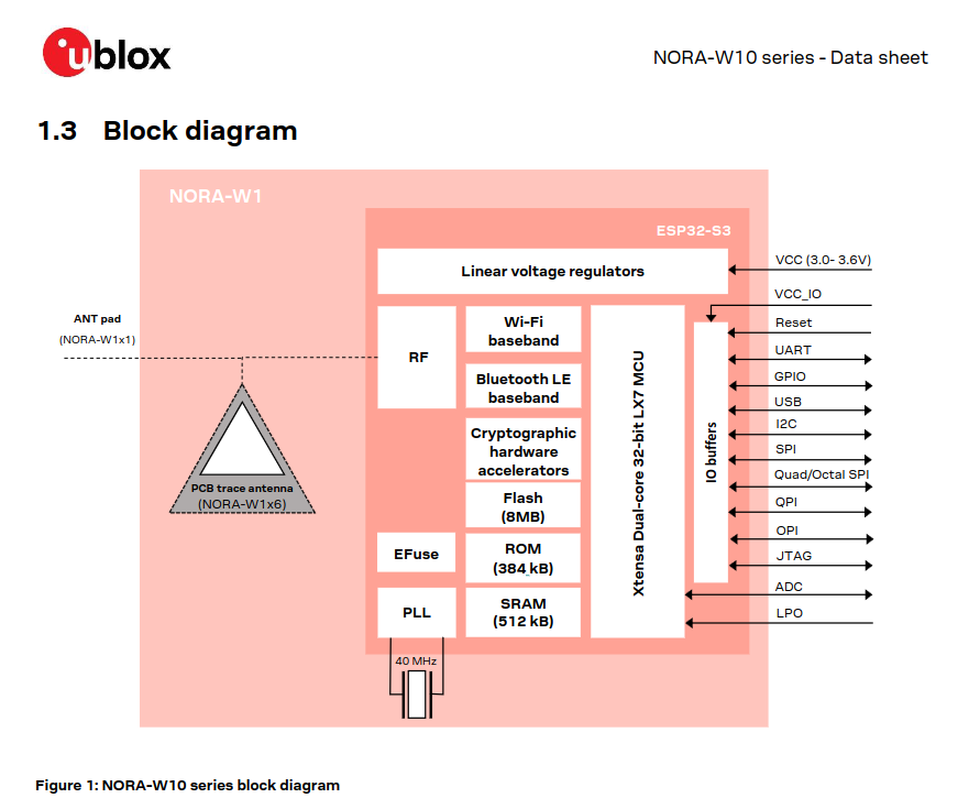
ublox NORA-W10 series - Data sheet 1.3 Block diagram NORA-W1 ESP32-S3 Linear voltage regulators VCC (3.0- 3.6V) ANT pad (NORA-W1x1) RF Wi-Fi baseband Reset UART Bluetooth LE baseband GPIO Xtensa Dual-core 32-bit LX7 MCU USB I2C Cryptographic hardware accelerators
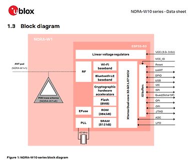
in „Arduino Nano mit ESP32-Prozessor“ · Mikrocontroller und Digitale Elektronik · · Diagramme
-
PDF
Schematic_Smart_Greenhouse_20200410231436.pdf
1 2 3 4 5 6 7 8 Temperature Sensor GY-BME280 JST-XH4P BU JST-XH4P ST Mikrocontroller 1 A VCC 2 1 1 ESP 32 - NodeMCU A GND 3 2 2 SCL 4 3 3 SDA 4 4 19 3.3V GND 38 18 37 Brightness Sensor EN P23 17 36 GY-302 JST-XH4P BU JST-XH4P ST SVP P22 BKL 10120500 16 35 VCC 1 1 1 SVN TX 1 GND 2 2 2 15 34 2 SCL 3 3 3 P34 RX 3 SDA 4 4 4 4 ADDR 5 14 P35 P21 33 13 P32 GND 32 B 12 P33 P19 31 B 11 P25 P18 30 Moisture Sensor 10 29 Soil Moisture Sensor v1.2 JST-XH3P BU JST-XH3P ST P26 P5 9 28 Capacitive Vcc 1 1 P27 P17 2 2 8 27 Soil Moisture Aout 3 3 P14 P16 7 26 Sensor
in „ESP 32 Schaltung“ · Mikrocontroller und Digitale Elektronik ·
-
PDF
SCH_Schematic1_2025-04-21.pdf
GND 14 R1k 10CS0 SCLK 13 Fan Header 11MISO MOSI 12 D D CN1 IO9 IO10 N N N ▯B 1 G G G ▯B FAN- 21 +12V 32 RPM1 43 PWM1 4 12V Controller 1 2 3 4 5 6 7 CN2 D1 1 2 3 4 5 6 7 H1 FAN- 11 +12V FAN- +12V 1 22 Q1 RPM2 M 33 PWM2 100▯' PWM1 P 44 R100 ' kR10k CN3 1 1 ▯C FAN- 1 21 GND ▯C +12V M 32 GND RPM3 W 43 PWM1
in „PWM Lüfter Steuerung mit ESP8266 Tacho Problem“ · Mikrocontroller und Digitale Elektronik ·
-
Bild
Anleitung zur Pinbelegung und DIP-Schalter-Einstellung EXA-PROG
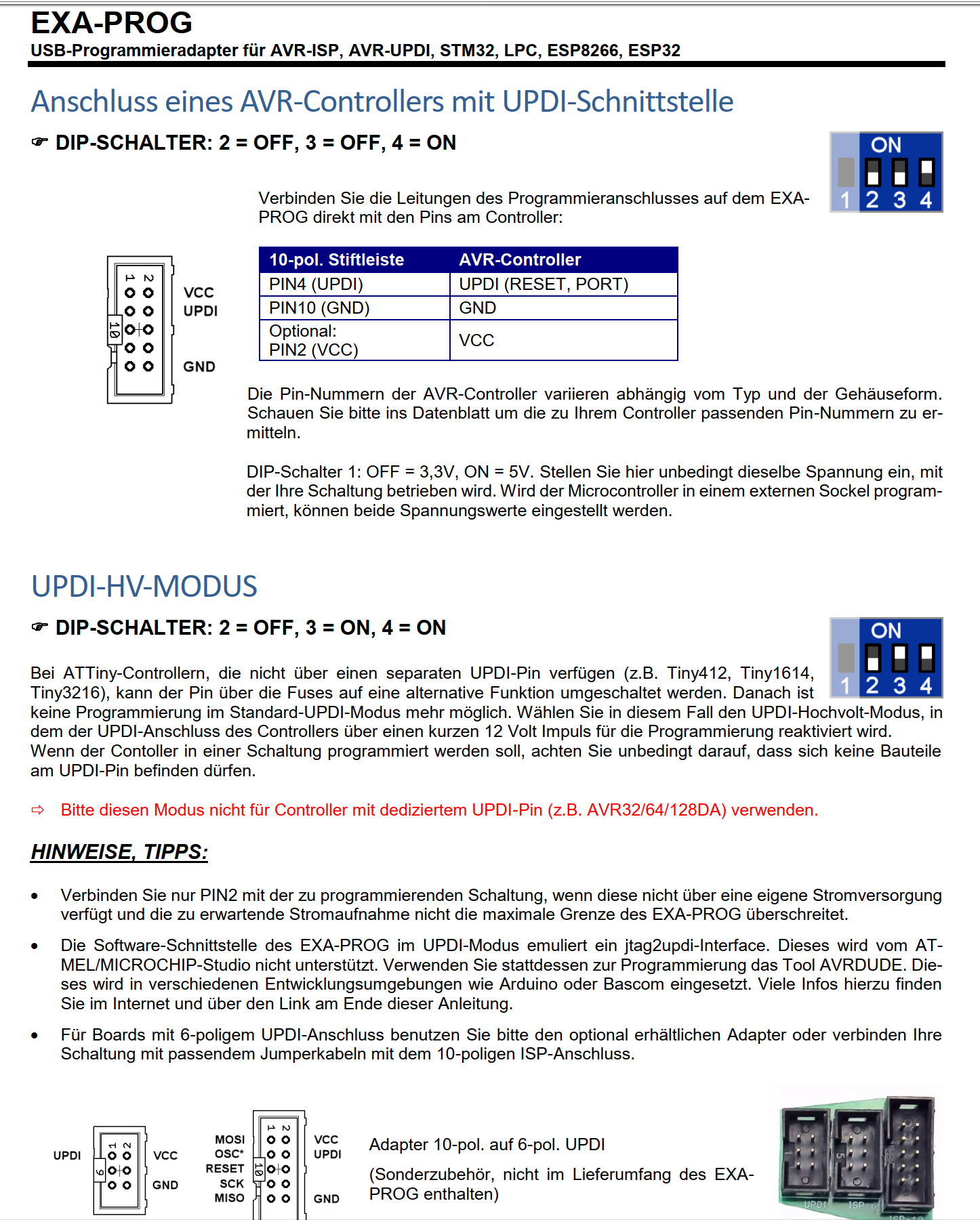
EXA-PROG USB-Programmieradapter für AVR-ISP, AVR-POD, STM32, LPC, ESP3226 Anschluss eines AVR-Controller mit UPDI-Schnittstelle DIP-SCHALTER: 2 = OFF, 3 = OFF, 4 = ON 10-pol. Stecker PIN4 (UPDI) PIN10 (GND) Optional: PIN2 (VCC) AVR-Controller UPDI (RESET, PORT
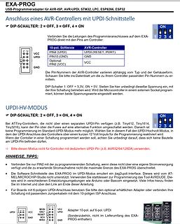
in „UPDI Programmierung mit dem Diamex“ · Mikrocontroller und Digitale Elektronik · · Screenshots
-
Bild
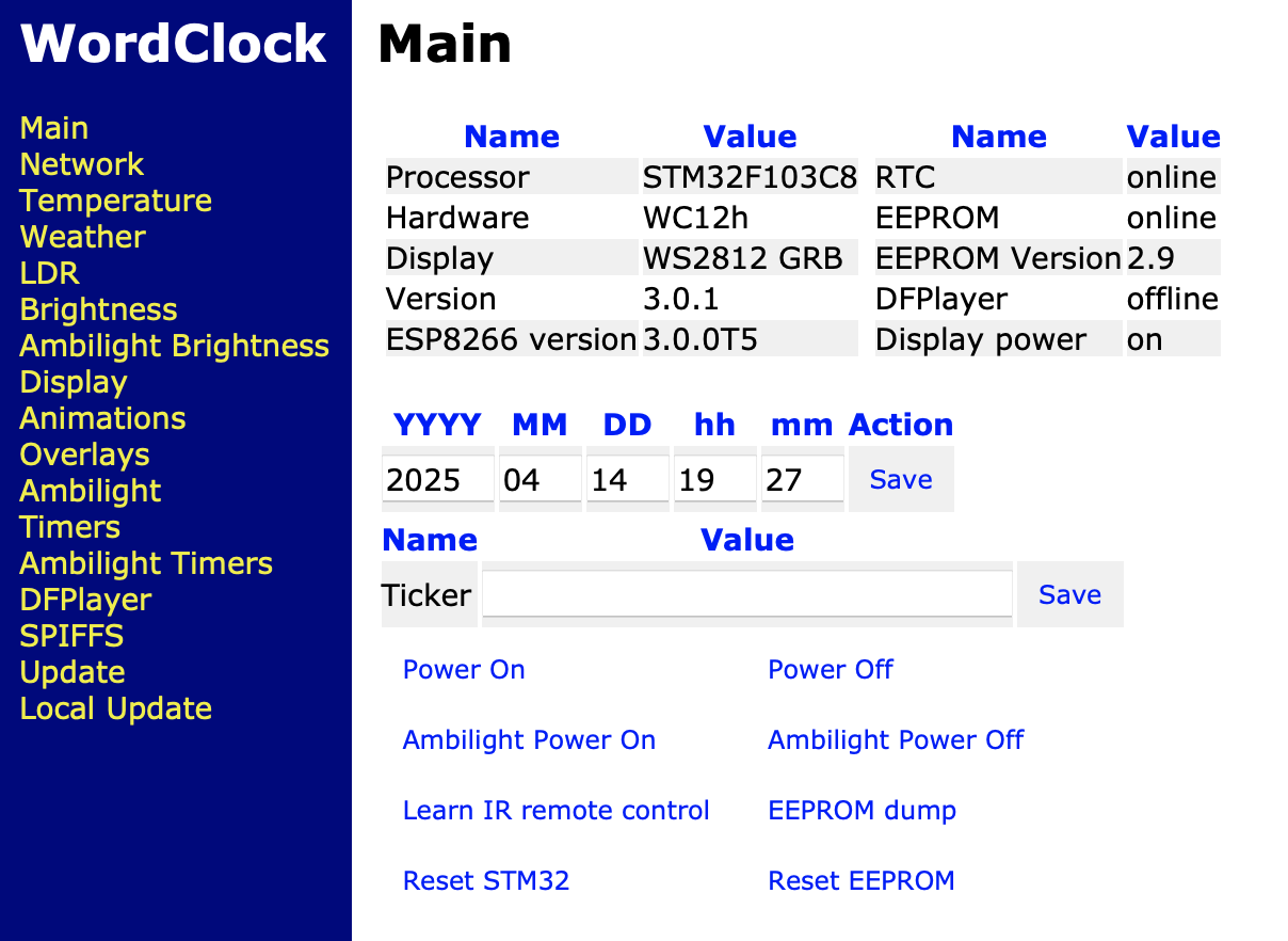
Webinterface einer WordClock Steuerung
Animations Overlays Ambilight Timers Ambilight Timers DFPlayer SPIFFS Update Local Update Processor STM32F103C8 Hardware WC12h Display WS2812 GRB Version 3.0.1 ESP8266 version 3.0.0T5 RTC online EEPROM online EEPROM Version 2.9 DFPlayer offline Display power on YYYY MM DD hh mm Action 2025 04 14 19 27 Save
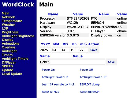
in „WordClock mit WS2812“ · Projekte & Code · · Screenshots
-
PDF
D_Vivaro_TD_Kap_4.pdf
............................................................................................ 3 - 7 ESP .................................................................................................................................. 3 - 8 Vorderachse..................................................
in „Wie wird eine zweite Batterie eingebaut?“ · Fahrzeugelektronik ·
-
Bild
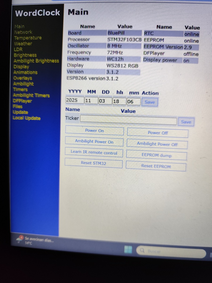
Abfotografierter Bildschirm einer Web-Oberfläche für ein STM32-Projekt
Ambilight Timers DFPlayer Files Update Local Update Name Value Board BluePill RTC online Processor STM32F103C8 EEPROM online Oscillator 8 MHz EEPROM Version 2.9 Frequency 72MHz DFPlayer offline Hardware WC12h Display power on Display WS2812 RGB Version 3.1.2 ESP8266 version 3.1.2 YYYY MM DD hh mm Action
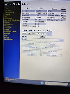
in „WordClock mit WS2812“ · Projekte & Code · · Fotos
-
Bild
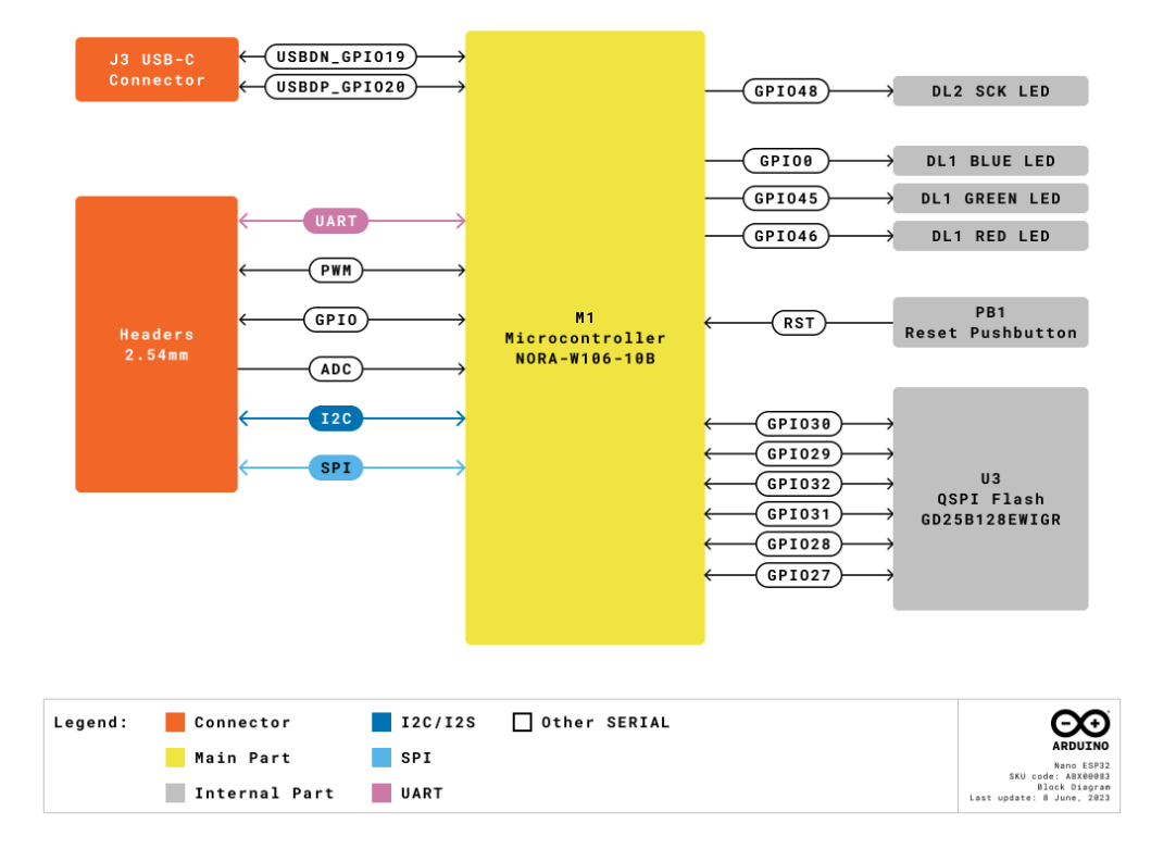
Blockschaltbild eines Mikrocontrollers NORA-W106-10B
, GPIO, ADC, I2C, SPI, PB1 Reset Pushbutton, RST, U3 QSPI Flash GD25B128EWIGR, GPIO30, GPIO29, GPIO32, GPIO31, GPIO28, GPIO27, Legend: Connector, I2C/I2S, SPI, UART, Main Part, Other SERIAL, Internal Part, ARDUINO Nano ESP32, SKU code: AR800083, BSKU Display, Last update: 8 June, 2023
in „Arduino Nano mit ESP32-Prozessor“ · Mikrocontroller und Digitale Elektronik · · Diagramme
-
Bild
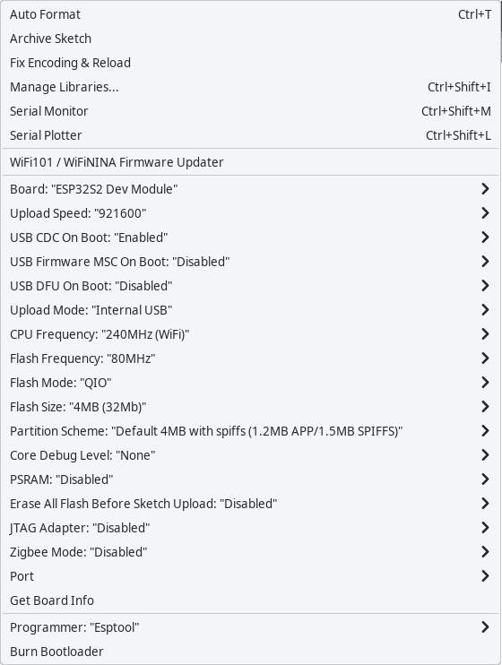
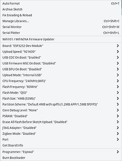
Arduino IDE Board Konfiguration WiFi101 / WiFiNINA
Serial Monitor Ctrl+Shift+M Serial Plotter Ctrl+Shift+L WiFi101 / WiFiNINA Firmware Updater Board: "ESP32S2 Dev Module" Upload Speed: "921600" USB CDC On Boot: "Enabled" USB Firmware MSC On Boot: "Disabled" USB DFU On Boot: "Disabled" Upload Mode: "Internal USB" CPU Frequency: "240MHz (WiFi)" Flash Frequency: "80MHz" Flash Mode: "QIO" Flash Size: "4MB (32Mb)" Partition Scheme: "Default 4MB with spiFFS (1.2MB APP/1.5MB SPIFFS)" Core Debug Level: "None" PSRAM: "Disabled" Erase All Flash Before Sketch Upload: "Disabled" JTAG Adapter: "Disabled" Zigbee Mode
in „Sammelbestellung AR488 kompatibler USB-GPIB Adapter. Interesse?“ · Mikrocontroller und Digitale Elektronik · · Screenshots
-
Datei
test3.2.ino
#include <WiFi.h> #include <FirebaseESP32.h> //#include <DHT.h> #include <NTPClient.h> #include <WiFiUdp.h> #include <IRremoteESP8266.h> #include <IRrecv.h> #include <IRutils.h> #define WIFI_SSID "Herech" #define WIFI_PASSWORD "here" #define
in „ESP32 Automatic Reset after one cycle“ · Mikrocontroller und Digitale Elektronik ·
-
Bild
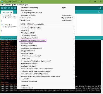
Screenshot der Arduino IDE mit ESP8266 Firmware-Einstellungen
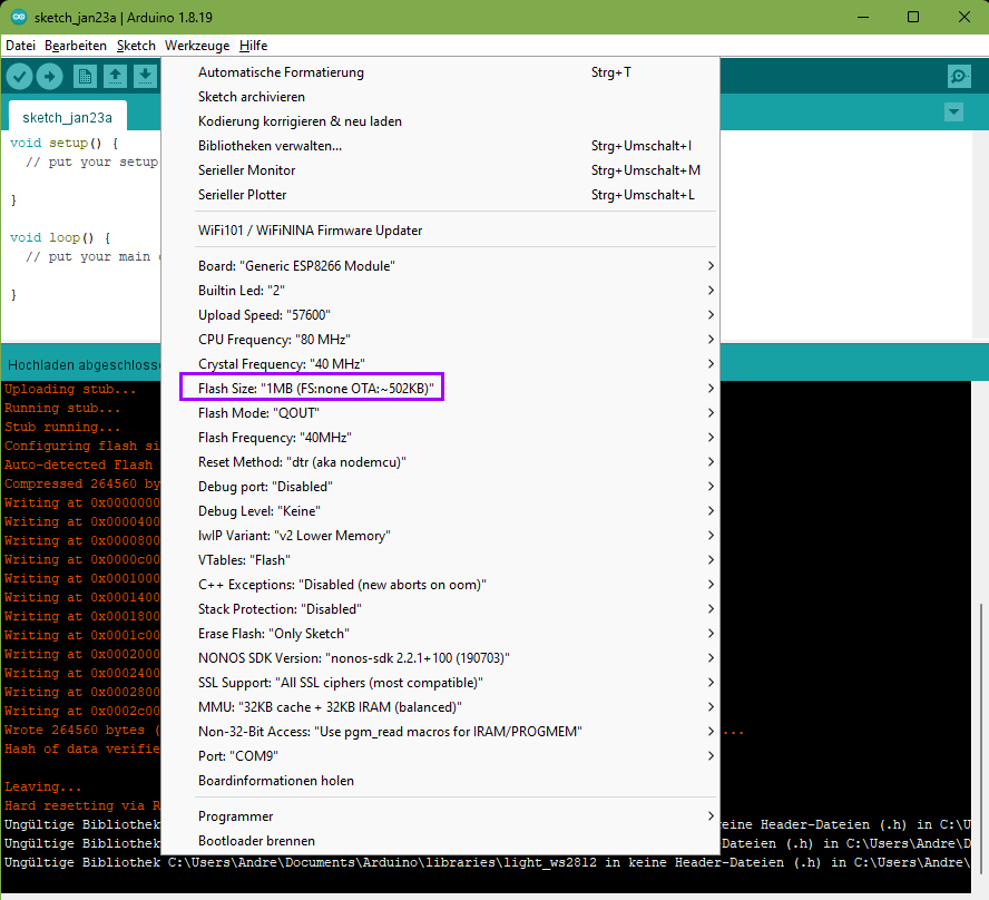
Werkzeuge Hilfe void setup() { // put your setup } void loop() { // put your main } Board: Generic ESP8266 Module Builtin Led: "2" Upload Speed: "80 MHz" Crystal Frequency: "40 MHz" Flash Size: "1MB (FS:none OTA:~502KB)" Flash Mode: "QOUT" Flash Frequency: "40MHz" Reset Method: "dtr (aka nodemcu)" Debug
in „ESP32-01 WiFi“ · Mikrocontroller und Digitale Elektronik · · Screenshots
-
PDF
Stromlaufplan.pdf
| Rücklicht 12V | Bremslicht 0V | GND 1N4007 DC/DC Wandler 5V IN + OUT + 1N4007 IN - OUT - Relais ESP32 Stecker S NO 3V3 GND + COM Rück DC/DC Wandler 3.3V EN G23 - NC Brems GND IN + OUT + SP G22 SN TXD IN - OUT - G34 RXD G35 G21 G32 GND G33 G19 G25 G18 G26 G5 MPU6050 G27 G17 VCC G14 G16 GND G4 G12 SCL
in „Schon der zweiten ESP32 abgeraucht“ · Fahrzeugelektronik ·
-
Bild
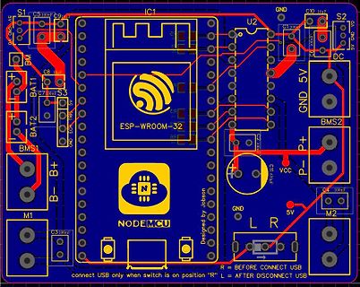
PCB-Layout eines ESP-WROOM-32 NodeMCU Moduls
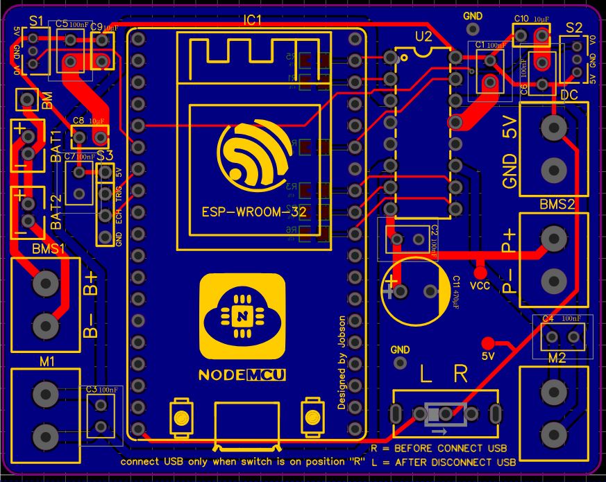
S1 C5 100nF C9 10uF IC1 GND C10 10uF S2 U2 C6 100nF C1 100nF GND 5V DC BMS2 BAT1 C8 10uF C7 100nF S3 GND ECH TRIG 5V C2 100nF P+ C11 470uF P- BMS1 B+ VCC GND 5V M2 C4 100nF B- M1 C3 100nF L R Designed by Jobson NODEMCU R = BEFORE CONNECT USB connect USB only when switch is on position "R" L = AFTER DISCONNECT USB
in „Micro Mouse Platinen Layout“ · Platinen · · Layouts
-
Bild
Fritzing-Schaltplan mit zwei ESP-WROOM-32 Modulen und Breadboard
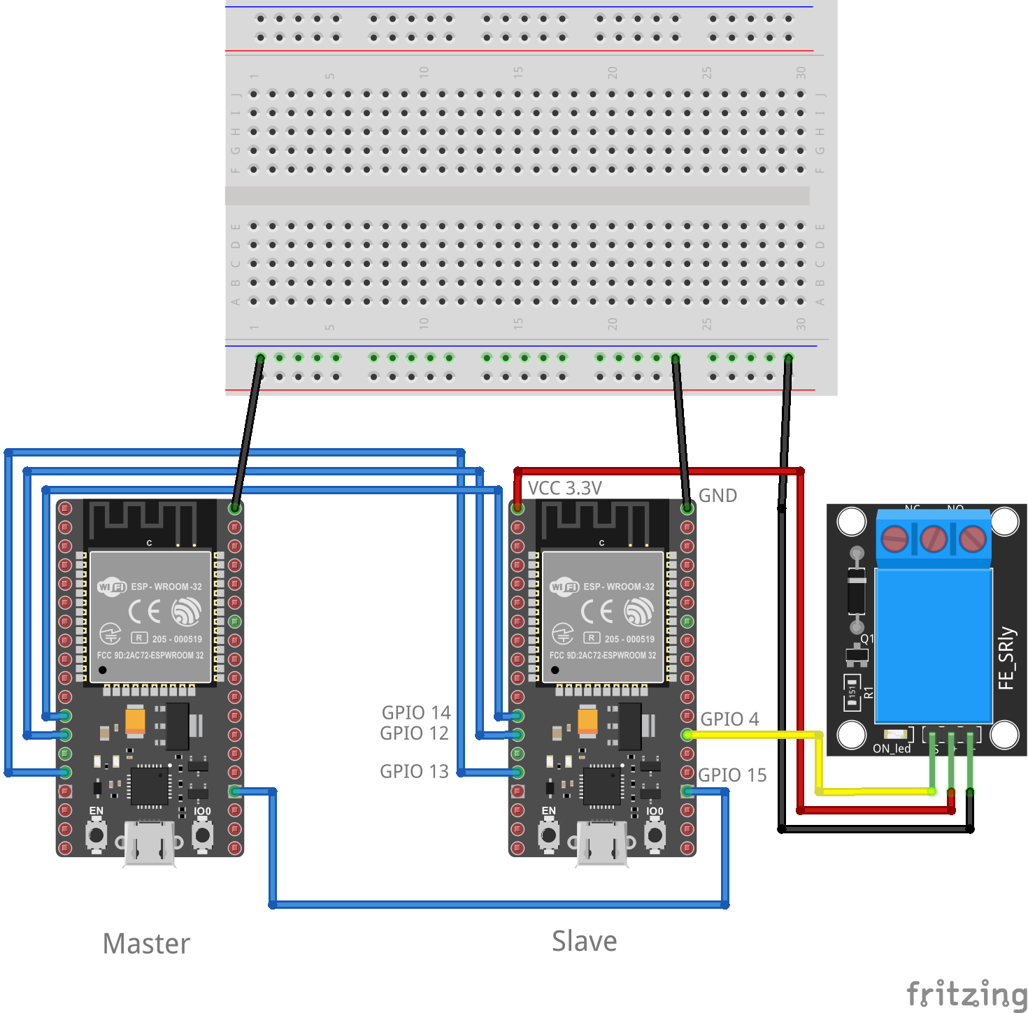
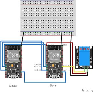
F G H I J 1 5 10 15 20 25 30 A B C D E 1 5 10 15 20 25 30 ESP-WROOM-32 CE R 205-000519 VCC 3.3V GND GPIO 14 GPIO 12 GPIO 13 GPIO 15 Master Slave FE_SRLY ON led fritzing
in „ESP-32 SPI sendet falsche bits“ · Mikrocontroller und Digitale Elektronik · · Screenshots
-
Bild
Arduino IDE mit ESP8266 Firmware Upload Log
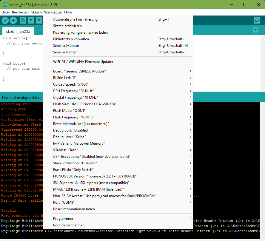
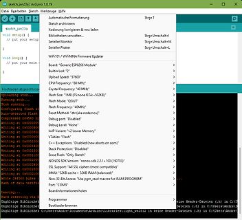
Werkzeuge Hilfe void setup() { // put your setup } void loop() { // put your main } Board: Generic ESP8266 Module Builtin Led: "2" Upload Speed: "57600" CPU Frequency: "40 MHz" Crystal Frequency: "40MHz" Flash Size: "1MB (FS:none OTA:502KB)" Flash Mode: "QOUT" Flash Frequency: "40MHz" Reset Method: "
in „ESP32-01 WiFi“ · Mikrocontroller und Digitale Elektronik · · Screenshots
-
Bild
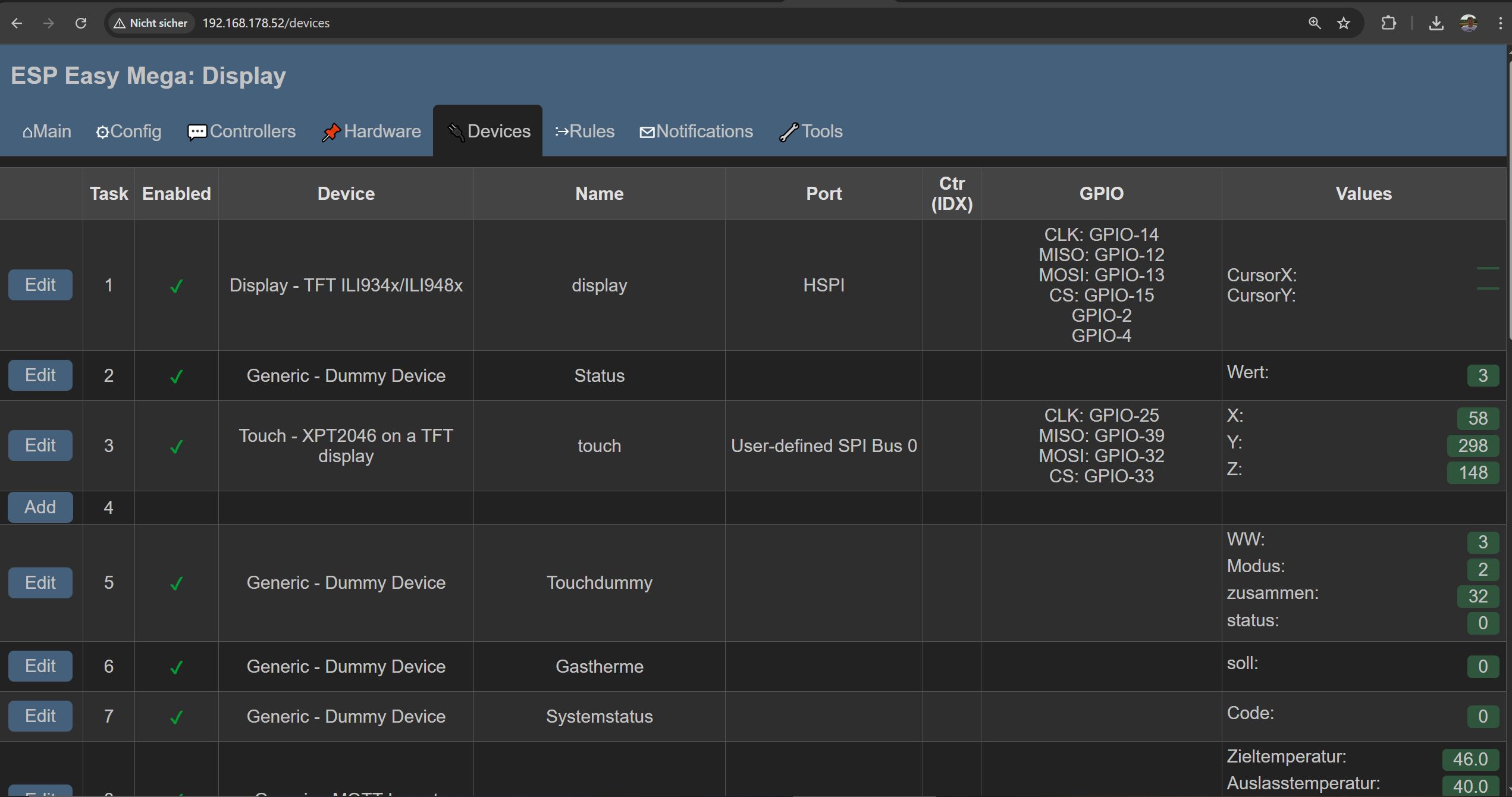
Webinterface ESP Easy Mega Display Konfiguration
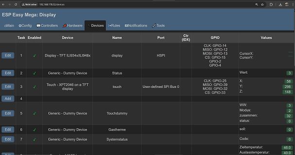
ESP Easy Mega: Display Main Config Controllers Hardware Devices Rules Notifications Tools Task Enabled Device Name Port Ctr (IDX) GPIO Values Edit 1 Display - TFT ILI934x/ILI948x display HSPI CLK: GPIO-
in „Günstiges und einfaches Mini-Controller Board, was würdet ihr heute nehmen?“ · Mikrocontroller und Digitale Elektronik · · Screenshots
-
Datei
modules_install_file_list_LK5.2-RC2.txt
ieee802154.ko INSTALL net/ieee802154/ieee802154_socket.ko INSTALL net/ipv4/ah4.ko INSTALL net/ipv4/esp4.ko INSTALL net/ipv4/esp4_offload.ko INSTALL net/ipv4/gre.ko INSTALL net/ipv4/inet_diag.ko INSTALL net/ipv4/ip_gre.ko INSTALL net/ipv4/ip_tunnel.ko INSTALL net/ipv4/ipcomp.ko INSTALL net/ipv4/ipip.ko
in „Linux Kernel 5.1.1. auf dem BPi-R2“ · PC Hard- und Software ·
-
PDF
controller.pdf
Size: A4 Date: Rev: KiCad E.D.A. kicad (5.1.5)-3 Id: 2/3 1 2 3 4 5 6 1 2 3 4 5 6 +3.3V +3.3V +3.3V J32 10K Micro_SD_Card C6 C7 C8 C9 C21 C11 C10 C23 R7 0.1uF 0.1uF 0.1uF 0.1uF 0.1uF 0.1uF 0.1uF 0.1uF 10K 10K RESET R28 R29 1 C13 DAT2 GND 0.1uF SW1 SD_CS 2 DAT3/CD A SW_Push SD_MOSI 3 CMD A 4 VDD SD_SCK
in „lpc1768 uart Bootloader funktioniert nicht“ · Mikrocontroller und Digitale Elektronik ·
-
Bild
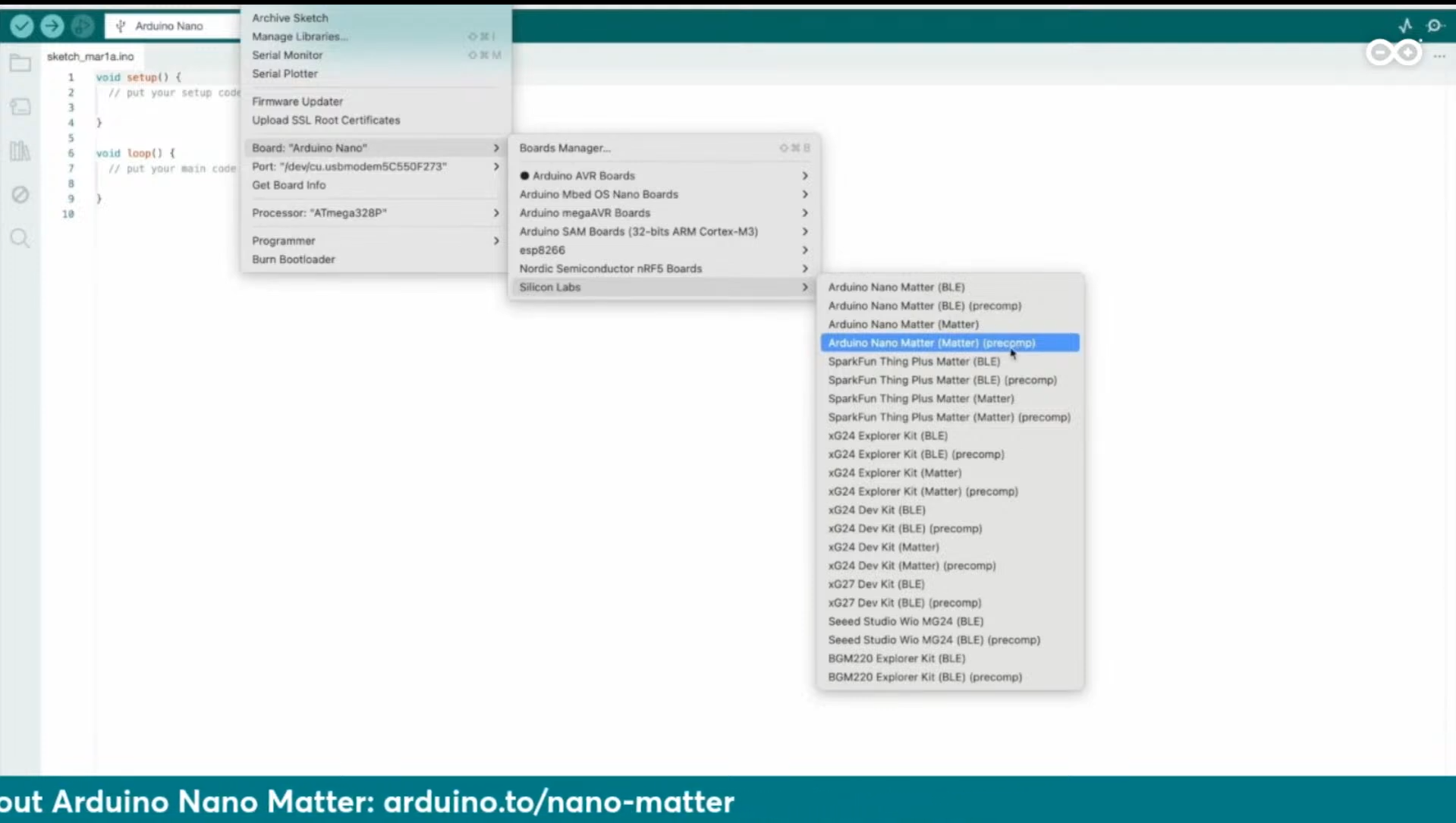
Arduino IDE Board Manager Menü mit Arduino Nano Matter
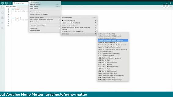
Manager... Arduino AVR Boards Arduino Mbed OS Nano Boards Arduino megaAVR Boards Arduino SAM Boards (32-bits ARM Cortex-M3) ESP32 Nordic Semiconductor nRF5 Boards Arduino Nano Matter (BLE) Arduino Nano Matter (precomp) Arduino Nano Matter (Matter) Arduino Nano Matter (Matter) (precomp) Silicon Labs SparkFun
in „Arduino Days: Neuer Matter-Arduino, Erweiterungen für Arduino-SPS und Cloud“ · Mikrocontroller und Digitale Elektronik · · Screenshots
-
Datei
global.h
HOUR][_MINUTE][_SECOND] int _act_date_time[6]; //[_YEAR][_MONTH][_DAY][_HOUR][_MINUTE][_SECOND] uint32_t _timestamp = 0; uint32_t _previousMillis = 0; uint32_t _secondMillis =0; uint _secAdjust=1000; int _oledDisplayWait=0; int _httpMarker = 0; //int _VCC = 0; bool _sendingOK=false; float _pressure; float
in „ESP Temperaturmodul mit DS18B20 und Web-Ansicht“ · Mikrocontroller und Digitale Elektronik ·
-
Datei
implizit.txt
beziehe mich im folgenden auf die k8055d.dll vom April 2004 mit 21 Funktionen. Also: Wie macht man eine 32-Bit Importlibrary, wenn man keine Objektdateien und keine Quelldateien hat? Diese Frage hat schon Microsoft bewegt... http://support.microsoft.com/default.aspx?scid=kb;en-us;131313 (Ob die dreifache
in „Velleman K8055 und Cygwin GCC...“ · Softwareentwicklung ·
-
Datei
putty.txt
... button_init... timer2_init... wpsbutton_init... Version: 2.9.5 Hardware: STM32F103 Display: WC12h LEDs: WS2812 GRB rtc is online eeprom is online ws2812: no external pullup detected eeprom is online current eeprom version: 0x00020900 reading ir codes from eeprom DFPLAYER LOGGER ESP8266 LOGGER read rtc: Tu 2019-03-19 21:59:27 read rtc: Tu 2019-03-19 21:59:27 net_time_countdown = 3794, don't check overlays read rtc: Tu 2019-03-19 21:59:45 RTC temperature: 20 read rtc: Tu 2019-03
-
Datei
main.c
regulary calls a interrupt routine, lighting up one of 24 segments every cycle. the displaybuffer is a 32bit int as binary (24 bit used), containing following (from LSB): 7 bits of second 7 segment digit (ones) 7 bits of first 7 segment digit (tens) 1 bit for flash symbol 1 bit for percent symbol 5 bits
in „fumot 12.000-Puffs Einweg-Vape mit LED-Display“ · Offtopic ·
-
Datei
EmsBus.java
public class EmsBus { private String emsServer = "192.168.254.115"; private int emsPort = 23; // EMS-ESP-Link: raw debug port private static String syslogServer = "192.168.254.20"; private static int syslogPort = 514; private static int useSyslog = 1; // use syslog instead of stdout static SyslogIF syslog
-
PDF
iot.pdf
A RTS 12k 1 3 IO0 A N 2 B C N G 3 GND R14 E G A 0,1uF k C A R 1 C43 0,1uF VDD3V3 0,1uF C52 IC1 N N ESP32-WROOM-32D__4MB_ 3 C1 1 20 G G R R76 2 RESET/OSR0 SDI/OSR1 19 2 1 1 25 T CP1 R100 3 DVDD SDO 18 2 GND_1 IO0 26 N FB0 10k 4 AVDD SCK/MCLK 17 3 3V3 IO4 27 2 2 1 2 H R4 10 5 CH0+ CS/BOOST 16 E D 4 EN
in „Schaltung des IOT-Steckdoses mit Eagle entwickeln“ · Mikrocontroller und Digitale Elektronik ·
-
Bild
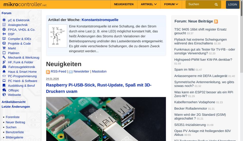
Screenshot der Webseite mikrocontroller.net
:47 Anlassersperre mit DEFA Ladegerät 01:40 Symmetrische Antennenleitung, wie gibts sowas noch? 01:32 Was kann ein ESP32 besser als ein RPi Zero-W? 01:29 Kabelfernsehen Vodafone 01:23 Becker Rolladenmotor 01:21 Wann wird der 2G Standard (GSM) abgeschaltet? 01:21 Si5351-Initialisierung 01:09 Akkus 00:
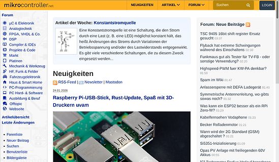
in „Desktop Ansicht will nicht beim Smartphone“ · Offtopic · · Screenshots