Counts AC Voltmeter, Prüfspannung, Isolationswiderstand 200GΩ mit großem LCD-Display https://amzn.eu/d/4D0Mz4C
Festinstallationen an 230V Dielectric strength 750 VAC, 50/60 Hz for 1 min between contacts of same polarity 2,000 VAC, 50/60 Hz for 1 min between coil and contacts Impulse withstand voltage 4,500 V between coil and contacts Aber man muss die Platine natürlich passend designen. Wenn die Steuerseite
for Figure 6-19. Output Spectral Noise Density vs Frequency for Legacy Chip New Chip 100 d 100 ) VIN 4.3 V - 1mA d 90 V = 3.3 V o 90 50mA o 80 OUT c 80 a COUT = 10mF OUT = 1 mA j R 70 TJ= +25°C R 70 n e t 60 p 60 j i e 50 y 50 y p p 40 u 40 u 30 S V = 4.3V - I = 50 mA e 30 IN e 20 OUT o VOUT = 3.3V w
with 'E' followed by an exponent number to denote exponential notation. For example 1.6E+4 is the same as 16000. When a constant number is used it will be assumed that it is an integer if a decimal point or
b m e h e c e S R 8 0 5 0 . e V . . 2 I l 1 n a A d l , K B g n 0 r m 8 r a N H r o B y K – L y a a g u i a D o t G a b m e h e c e S R 8 0 5 0 . e V . . 2 I l 1 n a A d l , K B g n 0 r m 8 r a N H r o B D
V4 p Power Save E - VDD COMS 2 uO n These are the COM output terminals for the indiBoth terminals output the same signal. S output by both master and slave.e not usWhen in master/slave mode, the same signal
p 4 4 p 1 s 2 p u r A 1 t A 1 o A 1 t o 0 m e 1 s e V s e V 2 s V t i ) N A i ) I 1 i e I A a I f T r d I e T r d r T r o e p a t o i t m Q e t m i e n u r Q t u r t d u e Q n r s a c e e a c m T n a c t T h t r o l 4 t T w e 1 t h e 2 t w e l f n R r o 0 R r o ” R r h 0 u r at o e - “ e - “ e e o o v g t C i e t T n t T n t : O si 4 T O s 1 O e 2 ( s t e B 0 eA A ( e A ( s r e o o o V ge e e b e e b e e b N l n I
this example. Note that ST failed here because different Nucleo boards use different names for the same LEDs. So much for code portability. This is a good time to note the names used by your board: here they are “LD2” and “LD3”. Page 2 of 17 The next step is to configure the various options for LwIP.
concatenate the multiple UPG BANK file DATA to make a UPA file. The header has to be changed, it is the same except the last byte. All formats have "ef bb bf 00 00 03". The last byte is: SINGLE=28, BANK=29, ALL=5e. The text block offsets are essentially the same, although the number="" differs, as it is 1
To setup the display you use the BITBANG LCD INIT command: BITBANG LCD INIT d4, d5, d6, d7, rs, en d4, d5, d6 and d7 are the numbers of the I/O pins that connect to inputs D4, D5, D6 and D7 on the LCD module (inputs D0 to D3 and R/W on the module should be connected to ground
Back-upoperation Batterywarningdetectiv e voltage 3.2V(typ) 2.76V(typ) Batteryalarmdetectiv e voltage Figure 3-1 Classification of Operating State S5094873B-4/22 3.3.1 Normal Operating State Counting operation of single and multiple turns data
A B C D E +5V 1 LCD Timing Ciruit +5V 10K External RAM Connection A15 2 R3 LCD Interface U3D U5 U6 U3C C8 10K U3A e e 0 1 2 3 4 5 6 7 AD0 12 D n S b t t t t t t t t AD1 2 D1 Q1 19 10 A0 D0 11 WR 9 11 1 N 5 o e / n a a a a a a a a 3 18 9 12 8 13 3 ENABLE 3 G + C R R E D D D D D D D D AD2 4 D2 Q2 17 8 A1 D1 13 RD 10 33pF 2 AD3 5 D3 Q3 16 7 A2 D2 15 0 1 2 3 4 AD4 6 D4 Q4 15 6 A3 D3 16 74HC00 1 2 3 4 5 6 7 8 9 1 1 1 1 1 AD5 D5 Q5 A4 D4 74HC00 74HC00 AD6 7 D6 Q6 14 5
Proven Classic Hardware ISP for all Windows Platforms Application Builder AVR Studio 3 and AVRStudio4 included STK200 AVREdit and A complete Starter Kit for AVRGCC included AVR microcontrollers The best starter kit ever The STK200 supplied by Kanda to Atmel was the most successful starter kit EVER pro
Holes Insulating sleeve Blank Blank 4 2 0.1 a m 30 5 30 30 1 2 D 2 Safety vent L 2 max. 6.0 1 22.5 0.2 L A R G E FREQUENCY COEFFICIENT OF PERMISSIBLE RIPPLE CURRENT T Y Frequency P WV 50Hz 120Hz 300Hz 1kHz 10kHz S ~ 100 0.85 1.00 1.06 1.15
ANALOG COMPARATOR OFFSET VOLTAGE vs. COMMON MODE VOLTAGE V = 5V cc 18 16 T A 25˚C 14 V m 12 T = 85C e A a 10 l V e 8 f O 6 4 2 0 0 0.5 1 1.5 2 2.5 3 3.5 4 4.5 5 Common Mode Voltage (V) Figure 42. Analog Comparator Offset Voltage vs. Common Mode Voltage ANALOG COMPARATOR OFFSET VOLTAGE vs. COMMON MODE
1% metal film resistors.). Calculate R 2ith Equation 2. (2) Select R 1o be 1 kΩ, 1%. Solve for R in E2uation 3. (3) R = 1 k (16.26 − 1) = 15.26 k, closest 1% value is 15.4 kΩ. 2 R2= 15.4 kΩ. 9.2.2.2.2 Inductor Selection (L1) 1. Calculate the inductor Volt • microsecond constant E × T (V × μs), with Equation 4: (4) where • VSAT = internal switch saturation voltage = 1.16 V • VD= diode forward voltage drop = 0.5 V Calculate the inductor Volt • microsecond constant (E × T), (5) 2. Use the E × T value from the
The fault code always consists of a five-character Px1xx Fuel and air metering alphanumeric value, e.g. P0112. Px2xx Fuel and air metering Px3xx Ignition system The first character is a letter. It identifies the Px4xx Additional emission control system type: Px5xx Cruise and idle speed control Px6xx
d e r f r f e a d e e e s e e e h f b m l b p b p s f m s n s f u s e ö r e a a e l e l r u a r i r r t r i L H K G L H G K G K D L L D WD K S D t 8 9 0 2 1 2 6 9 0 0 8 8 7 0 8 a 6 9 6 2 3 4 4 6 6 6 6 7
/packaging D A b2 B 0.15 C A (DATUM A) E1 E (DATUM B) 1 2 3 e e1 TOP VIEW 4X A 0.08 C A1 C A A2 SEATING PLANE 3x b2 A SIDE VIEW 0.10 C A H c L VIEW A-A Microchip Technology Drawing C04-032 Rev D Sheet 1 of 2 DS20006033E-page 12 2018-2022MicrochipTechnologyInc.anditssubsidiaries
wenn der Hersteller oder ein Kunde dich "verklagt"? Sehe kein Problem darin. Durch Corona und Hartz4 hab ich eh nichts mehr was man mir wegnehmen könnte. Die Nebeneinkunft läuft sowieso auf ein anderes Konto mit dem ich auch das Material kaufe.
übrigens ganz schön mutig, dein Zeug in der Bucht zu verkaufen! Du weist doch gar nicht um welches eBay-Profil es sich handelt!
Relations between Solar activity and Radio Wave Propagation </td> </tr> <tr> <td>98 </td> <td>Sam </td> <td>Jewell </td> <td>G4DDK </td> <td>A low cost 2.4GHz receive converter for mode S reception </td> </tr> <tr> <td>98 </td> <td>Dr. Jochen </td> <td>Jirmann
a millivolt of each other due to negative feedback, but comparator inputs are rarely kept at the same potential and can see several volts of 4 Application Design Guidelines for LM339, LM393, TL331 Family Comparators SNOAA35B – APRIL 2019 – REVISED AUGUST 2021 Including the New B-versions Submit Document
toamp range requires a device that can meas- A G R E A T E R M E A S U R E O F C O N F I D E N C E ure currents with a few tens of attoamps RMS noise in the range of 0.1 to 0.01Hz and, in the case of a demonstration setup, a cur- rent source with a resolution
zum tragen, ich hab es nur nebenbei gehört, das war echt informativ. https://www.youtube.com/watch?v=E0q9ictm1Kk , wie gesagt nicht genau das thema, aber vielleicht hilft es ja was.
halten. Naja, hättest mal das Dokument vollständig gelesen resp. durchgesehen: https://youtu.be/ygE01sOhzz0?t=55
www.t3vakfi.org/en/) nahm einen Listenplatz für den „aktivsten“ Entwickler ein. 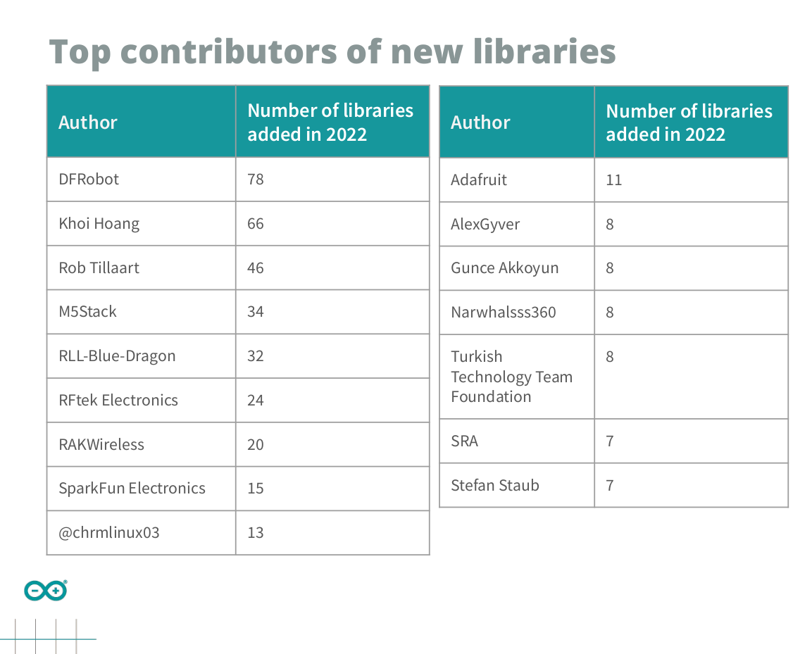 Bildquelle: Arduino. ### QT 6.5: Erweiterungen der seriellen Portklassen. Dass QT Embedded-Anwendungen als Wachstumsmarkt ansieht, ist bekannt - selbst wenn das unter https://www.mikrocontroller.net
bietet nun unter der URL https://github.com/Microchip-MPLAB-Harmony/reference_apps/tree/master/apps/sam_e54_xpro/same54_can_usb_bridge eine „durchimplementierte“ Beispiel-Applikation für das hauseigene SAM E54 Xplained Pro Evaluation Kit an, das - wie in Abbildung XXX gezeigt - ein Testsystem ermöglicht
de bel luidt, rijdt luidsterk het station binnen, wordt langzamer en stopt met luid gesis. TA1 - TA4 Taster | push button B207 | Som de maquina a vapor Com apito de comboio e sino de comboio Platine | Board IC1 ...reproduz o apito de um comboio assim como o assobio de uma maquina a Maße | Dimensions
i h r s x l i 6 E a c r O l h w g s 0 n .5 o g q n t I f a c s t g 9 - 5 H i s o 4 e 8 m h f o u p 7 0 1 . 1 g t 2 n 3 m s g c o a I " Ø 1 3 x i n F o 1 r l r M t D 9 o a I e e e M ( h s mp 2 t T i i 3 t ) u a 4 2 o i 2 d p 4 3 7 S ( 2 d 6 2 e 3 d 1 ) h 8 e ( l . H t 1 . 0 f 1 3 - l 4 1 x m 4 1 . f 2 Ø 5 m 2 9 x i M 6 4 m M 6 Fig. 1. Dimensional drawing EN1R-9162 0801R13-NE 2 Table 4: Operating pressure Inlet End outlet Side
changes to the code presented here, but the techniques for driving the display are essentially the same. Lookup tables To display each digit, a corresponding pattern of segments must be lit, as follows: Segment: A B C D E F G Pin: RC1 RC2 RC4 RC3 RB4 RB1 RB0 0 on on on on on on off 1 off on on off off
the default. To assign an IP address manually: 1. Click StartAll ProgramsLantronixDeviceInstaller 4.3DeviceInstaller. If your PC has more than one network adapter, a message displays. Select an adapter and click OK. Note: If the unit already has an IP address (e.g., DHCP has assigned an IP address
L Motorola Small–Signal Transistors, FETs and Diodes Device Data 3 2N2219 2N2219A 2N2222 2N2222A 1.4 +1.6 T = 25⋅C C 1.2 J V (25⋅C to 175⋅C) ( +0.8 S 1.0 E O I θVCfor CE(sat) ( 0.8 VBE(sat) IC B = 10 E 0 (–55⋅C to 25⋅C) 0 G C 0 L 0.6 VBE @ VCE = 1.0 V R –0.8 / , A 3 V 0.4 E M –1.6 θVB for BE 0 0.2 ,
ISA wieder unter dem alten Namen "POWER" gibt es bis heute. Mit PowerPC 601 in Unix-Clients und 604e in Servern hatte ich konkret zu tun. Eine Kiste mit POWER4 (kam 2001 raus, vgl PowerPC 970) läuft bis heute.
are four logarithm functions: LN(x), LOG2(x), LN(1+x), and LOG2(1+x). ; They share much of the same code, but are distinguished by two bits. ; In the same way, EXP(x), EXP2(x), EXP(x)-1, EXP2(x)-1 share the same ; startup code. ; BTLOGBASE2 .EQU 1 ; SET IF EITHER LOG2(
DievomSMGWfürdenAnschlussnutzeranderHAN-SchnittstellealsMinimumbereitzustellendenDaten. Die nachfolgende Tabelle 4.1 listet alle in Abschnitt 4.2 beschriebenen Anwendungsfälle auf. Abschnitt Anwendungsfall Abrechnungsrelevant 4.2.2 TAF1: Datensparsame Tarife ja 4.2.3 TAF2: Zeitvariable Tarife ja 4.2.4 TAF6: Ablesung
°C) Fig. 9 - High Output Voltage Drop vs. Temperature Fig. 11 - Output Low Voltage vs. Temperature 4 3.5 ) ) F = 0 mA ( ( Vout= 2.5 V n t VCC = 15 V e 3 e VEE= 0 V u u 2.5 C C u w t 2 L O t h IF= 16 mA p i V = (V - 4) V u 1.5 H 1 Vout= 15 V O -H CC L IO VEE = 0 V I 0 0.5 - 40 - 20 0 20 40 60 80 100
avalanche current i (0) =30 A ASd L loop3=928 µH. For simplicity, assume thatT j(start)25°C.FortheE ASdefinedwithinthe BSC014N06NSdatasheet,we had iAS4(0) = 50 A and Lloop4= 464µH.Notethatwehavechosenfor our examplea loop L loop3thatequalstwicethe value of Lloop4. ΔT Must remain the same forbothconditions.Consequently
INL 125C INL ) 260 -40C INL 25C INL 85C INL 125C INL 0.15 ) 260 -40C DNL25C DNL 85C DNL 125C DNL 0.4 W -40C DNL 25C DNL 85C DNL 125C DNL R INL ( 220 INL 0.1 ( 220 c DNL ) c DNL 0.2 b n s 0.05 S a s180 S s m80 ( s m 0 ( s h 0 r s o140 o e (o40 -0.05r R ( r r E r 100 RW -0.2 E p 100 RW -0.1 p i i -0.4
, set those timing data as the above data. 20 Doc . No LMS700KF05 Rev.No 000 Page /29 www.DataSheet4U.com Approval 6.3 Interface Timing Doc . No LMS700KF05 Rev.No 000 Page 21/29 w w w . D a t a S h e e t 4 U . c o m Approval 6.4 AC Characteristic (Ta=-20 to +60 °C) Parameter Symbol Min. Typ. Max. Unit
resistor values are shown below for PT2264 and PT2294. 100 R = 510 K R = 1 M R = 2 M 10 R = 3.3 M R = 4.7 M KHz 1 3 6 9 12 15 V O L T A G E PT2264 Encoder OSC Frequency PT2264 v1.0 - 6 - June, 2004 Tel: 886-2-66296288 URL: http://www.princeton.com.tw Remote Control Encoder IC PT2264 PT2294 DECODER OSC
Direction Input. All other Inputs will be interfaced the same. +5 VDC PIN 1 Opto Supply P1:1 OPTO SPPLY NC SCLK DIR Direction P1:4 EN GND +V TTL INTERFACE Figure 1.2.5: TTL Interface S w i t c h I n t e r f a c e Shown Connected to the Enable Input. The Direction
KMI16/1 PACKAGE OUTLINE Plastic single-ended multi-chip package; magnetized ferrite magnet (8 x 8 x 4.5 mm); 4 interconnections; 3 in-line leads SOT477B M 1 v M A B HE1 B K A E Q A L1 M2 bp1 D L v M A B E1 M3 H E SENSOR DIE POSITION D1 * centre of reading point L2 1 2 3 e1 b p c 0 2.5 5 mm e scale DIMENSIONS (mm are the original dimensions) UNIT A (1) bp bp1 c D(2) D (2) E(2) E (2) e e H H K L L L M M M (1) Q v 1 1 1 E E1 max. 1 2 1 2 3 1.7 0.8 1.57 0.3 4.1 5.7 4.5 5.7 4.6 2.35 18.2 5.6 mm 5.37 7.55 1.2 3.9 8.15 8.15 4.7 0.75 0.25 1.4 0.7 1.47 0.24 3.9 5.5 4.3 5.5 4.4
