-
 Bild
Bild
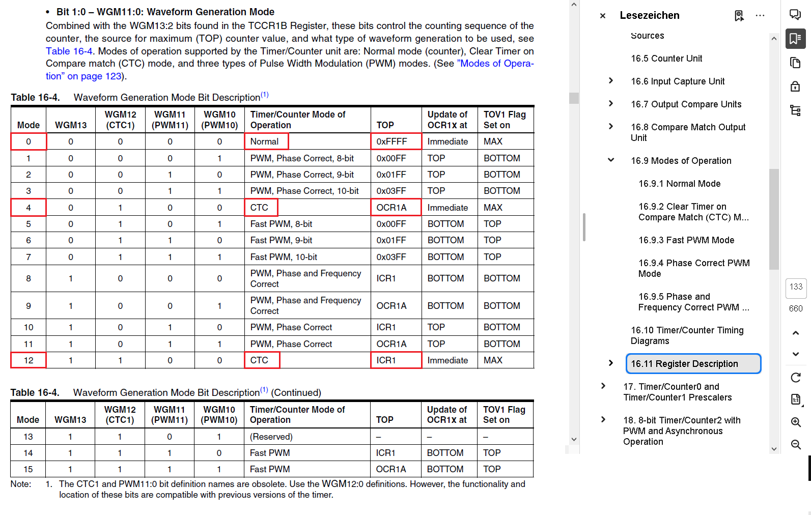
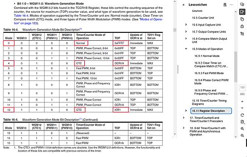
Tabelle der Waveform Generation Modi eines Mikrocontrollers
Timer/Counter Mode of Operation TOP TOV1 Flag Set on 1 0 0 0 Normal 0xFFF0 Immediate MAX 2 0 0 1 0 PWM, Phase Correct, 8-bit 0x00FF TOP BOTTOM 3 0 1 1 0 PWM, Phase Correct, 9-bit 0x03FF TOP BOTTOM 4 0 1 1 1 CTC 0CR1A Immediate MAX 5 1 0 0 1 Fast PWM, 8-bit 0x00FF BOTTOM TOP 6 1 1 0 1 Fast PWM, 9-bit 0x01FF BOTTOM TOP 7 1 1 1 Fast PWM, 10-bit 0x03FF BOTTOM TOP 8 1 1 1 0 PWM, Phase and Frequency Correct ICR1 BOTTOM BOTTOM 9 1 0 0 1 PWM, Phase and Frequency Correct OCR1A BOTTOM BOTTOM 10 1 0 1 0 PWM, Phase Correct ICR1 TOP BOTTOM 11
in „Atmega - Multiplex-Display-Ansteuerung fehlerhaft“ · Mikrocontroller und Digitale Elektronik · · Screenshots
-
PDF
Timer_Tiny85.pdf
Erklärung zu den Timern des Attiny85 Test PWM-Wert in Pulsbreite PWM-Periode Komentar # OCRxy / Timer-Takte / Timer-Takte 1 Timer 0, Fast PWM, timer mode 3 Pulsebreite 0 0 1 256 nicht direkt 1 2 256 möglich 2 3 256 3 4 256 252 253 256 253 254 256
in „Attiny85 Timer1 PWM: Keine Duty-Cycle-Formel (da nichtlinear?)“ · Mikrocontroller und Digitale Elektronik ·
-
PDF
Dokumentation.pdf
wurden folgende Funktionen getestet: • Digitale I/O • Analoge Eingänge einlesen und über LED anzeigen • PWM-Ausgang • PWM-Steuerung über Analogwerte • RS-232 Schnittstelle • Kombination von PWM-Steuerung über Analogwerte und RS-232 Ausgabe • Kommunikation zwischen µ-Controller und Display Die Kommunikation
in „Vielen Dank!“ · Mikrocontroller und Digitale Elektronik ·
-
Datei
Atmega_8_Solarpanel_ausrichten.c
main(void) { DDRB |= 0b00111110; DDRC |= 0b00000000; DDRD |= 0b00011111; // Grundeinstellungen für PWM // COM1A1 und B1 werden weiter unten eingeschaltet // TCCR1A |= (1<<COM1A1); // Compare Match Output A Mode; Non PWM Mode; Fast PWM Mode; Phase Correct PWM Mode // TCCR1A |= (1<<COM1A0); // Compare
in „ATMEGA 8 PWM geht nicht“ · Mikrocontroller und Digitale Elektronik ·
-
PDF
lpc1769_imu_v2.pdf
/MCABORT/PWM1.3/SSEL0 2 1 2 2 1 S B 1 0 11 VSSA BT_INT2/3.3A 36 P1.22/MC0B/USB_PWRD/MAT1.0 I UART2 +3V3 L 1 BT_INT1/3.3A 37 P1.23/MCFB1/PWM1.4/MISO0 P0.15/TXD1/SCK0/SCK 62 1 2 3 4 42 VDDREG3.3V 38 P1.24/MCFB2/PWM1.5
in „Schaltplan Prüfung/Kritik LPC1769 + IMU + Bluetooth“ · Mikrocontroller und Digitale Elektronik ·
-
PDF
Benezan_Breakout3.pdf
Breakoutboard einen Analogausgang 0..10V. Es wird eine Spannung proportional zum Tastverhältnis des PWM-Signals (PWM = pulse width modulation) an Pin 1 oder 17 des LPT-Ports ausgegeben. Dabei entspricht 0% (low) einer Spannung von 0V, 10% entspricht 1V, 20% 2V usw. bis 100% und 10V. Die Frequenz des PWM-Signals
in „Leadshine M542 - Geräusche bei Stillstand der Motoren“ · Mechanik, Gehäuse, Werkzeug ·
-
Datei
lib_AT91SAM7S256.h
AT91PS_PWMC pPWM) // pointer to a PWM controller { return pPWM->PWMC_SR; } //*---------------------------------------------------------------------------- //* \fn AT91F_PWM_InterruptEnable //* \brief Enable PWM Interrupt
in „C Datein werden in Eclipse nicht kompiliert“ · Mikrocontroller und Digitale Elektronik ·
-
PDF
tps92661-q1.pdf
6.6 Typical Characteristics TA= 25°C free air unless otherwise specified 6 6 ) 5.4 ) 5.4 A A ( 4.8 fPWM = 732 Hz ( 4.8 n fPWM = 146 Hz n r 4.2 r 4.2 u u s 3.6 s 3.6 i i B 3 B 3 i i r 2.4 r 2.4 e 1.8 e 1.8 f = 4185 Hz O O PWM u 1.2 u 1.2 PWM = 523 Hz n n PWM = 209 Hz I 0.6 I 0.6 0 0 -40 -25 -10 5 20 35
in „LED Serienschaltung mittels Transistor schalten“ · Analoge Elektronik und Schaltungstechnik ·
-
PDF
AVR450_BattCharger.pdf
The Fast_charge() Function for NiCd, Part 2(2) A NiCd_fast_2 B NO Temperature Within Limits ? Stop PWM and Flag Error YES NO Voltage Overflow ? Stop PWM and Flag Error YES NO 60 Sec. Over ? YES YES dT/dt Overflow ? Stop PWM Change Status toTrickle NO YES -dV Overflow ? Stop PWM Change Status toTrickle
in „Pb-Akku Ladegerät mit µP Selbstgemacht“ · Mikrocontroller und Digitale Elektronik ·
-
Datei
attiny45.bas
converter Do W = Getadc(1) Print #1 , "ADC : " ; W Waitms 500 Incr I Loop Until I = 30 Test: 'final use pwm mode of timer0 Config Timer0 = Pwm , Prescale = 1 , Compare A Pwm = Clear Down , Compare B Pwm = Clear Down Do Pwm0a = Pwm0a + 1 'increase the PWM value Pwm0b = Pwm0a Waitms 10 Loop 'note that TIMER1
in „Bascom - Pinbelegung in Testprogramm“ · Mikrocontroller und Digitale Elektronik ·
-
Datei
boards.h
_t wchannel); void set_pwm_change_mode(int boardnumber, int modenumber); void set_pwm_softlimit(int boardnumber, int softlimit); void set_pwm_defaultchangetime(int boardnumber, int changetime); void set_pwm_defaultchangetimeR(int boardnumber, int changetime); void set_pwm_defaultchangetimeG(int boardnumber, int changetime); void set_pwm_defaultchangetimeB(int boardnumber, int changetime); void set_pwm_defaultchangetimeW(int boardnumber, int changetime);
in „Timerberechnung die hunderste“ · Mikrocontroller und Digitale Elektronik ·
-
PDF
IFX9201SG-DS-v01.pdf
select (low active) 10 SCK SPI clock input 11 DIS Disable. Disables the outputs (all MOSFETS off) 12 PWM Pulse width modulation input Data Sheet 4 Rev. 1.1, 2015-02-15 IFX9201SG Pin Configuration 2.3 Terms IVS DIS VS V DIS VS DIR DIR V DIS PWM PWM VDIR V PWM I I OUT1 OUT1 CSN CSN I SCK SCK ISI SI IOUT2
in „Keine Open Load Meldung bei ata6836c und IFX9201SG!“ · Mikrocontroller und Digitale Elektronik ·
-
PDF
AS5047P_DS000324_2-00-1843440.pdf
direction. ams Datasheet Page21 [v1-01] 2016-Apr-28 Document Feedback AS5047P − DetailedDescription PWM ThePWMcanbeenabledwiththebitsettingPWMon.ThePWM encoded signal is displayed on the pin W or the pin I. The bit setting UVW_ABI defines which output is used as PWM.The PWM output consists of a frame of 4119 PWM clock periods, as shown in Figure 33. The PWM frame has the following sections: • 12 PWM Clocks for INIT • 4 PWM Clocks for Error detection • 4095 PWM clock periods of data • 8 PWM clock periods low
in „Bachelorarbeit über Drehwinkelsensor“ · Mikrocontroller und Digitale Elektronik ·
-
Datei
main.c
---------------------------------------------------- SIGNAL (SIG_OVERFLOW0) { static unsigned char PWM_cnt; #if (INVERT==1) if (PWM_cnt <Red) Ledport &=~(1 << R_PIN); else Ledport |= (1 << R_PIN); if (PWM_cnt <Green) Ledport &=~(1 << G_PIN); else Ledport |= (1 << G_PIN); if (PWM_cnt <Blue) Ledport &=
in „HSV RGB Led Dimmer, C Code & Video & Doku“ · Projekte & Code ·
-
PDF
ICE2AS01.pdf
3.2 Improved Current Mode Main Line (100V-380V) Soft-Start Comparator RStart-Up Primary Winding FB PWM-Latch C VCC R Q VCC Driver Power Management PWM Comparator S Q Undervoltage Internal Lockout Bias 13.5V 0.8V 8.5V Power-Down 6.5V PWM OP Reset 5.3V Voltage 4.8V Reference x3.65 Isense Power-Up 4.0V
in „TFT LP mit IC ICE2AS01 defekt“ · Mikrocontroller und Digitale Elektronik ·
-
 Bild
Bild
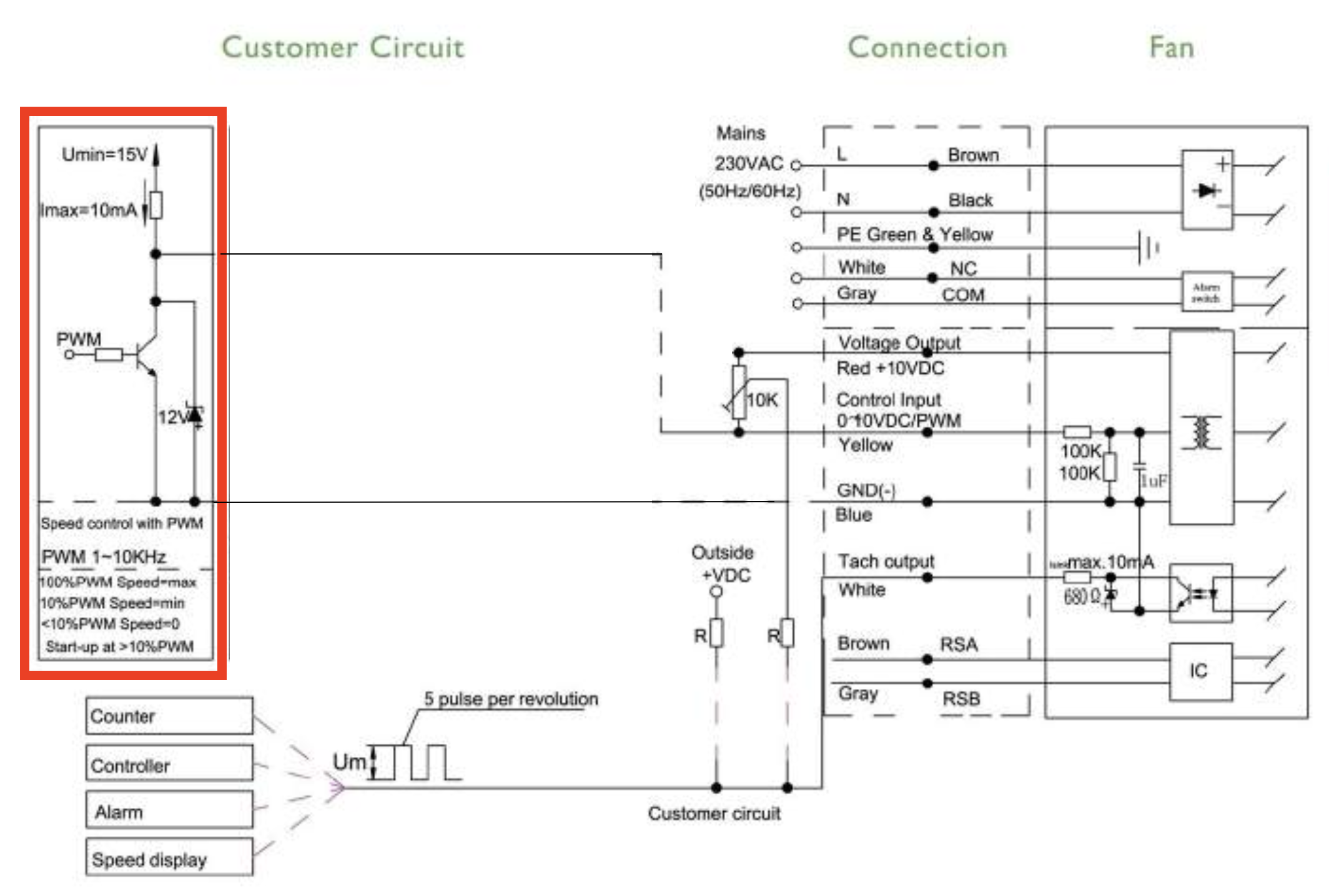
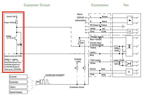
Schaltplan einer Lüftersteuerung mit PWM
Customer Circuit Connection Fan Umin=15V Imax=10mA PWM 1~10kHz 100%PWM Speed=max 10%PWM Speed=min <10%PWM Speed=0 Start-up at >10%PWM Mains 230VAC (50Hz/60Hz) L Brown N Black PE Green & Yellow White NC Gray COM Voltage Output Red +10VDC Control Input 0-10VDC/PWM Yellow GND(-) Blue 100K 100K uF Imax=10mA Tach output White Outside +VDC R R RSA Brown Gray RSB IC Counter Controller Alarm Speed display 5 pulse per revolution Um
in „Komische PWM Ansteuerung eines Lüftermotors?“ · Analoge Elektronik und Schaltungstechnik · · Schaltpläne
-
 Bild
Bild
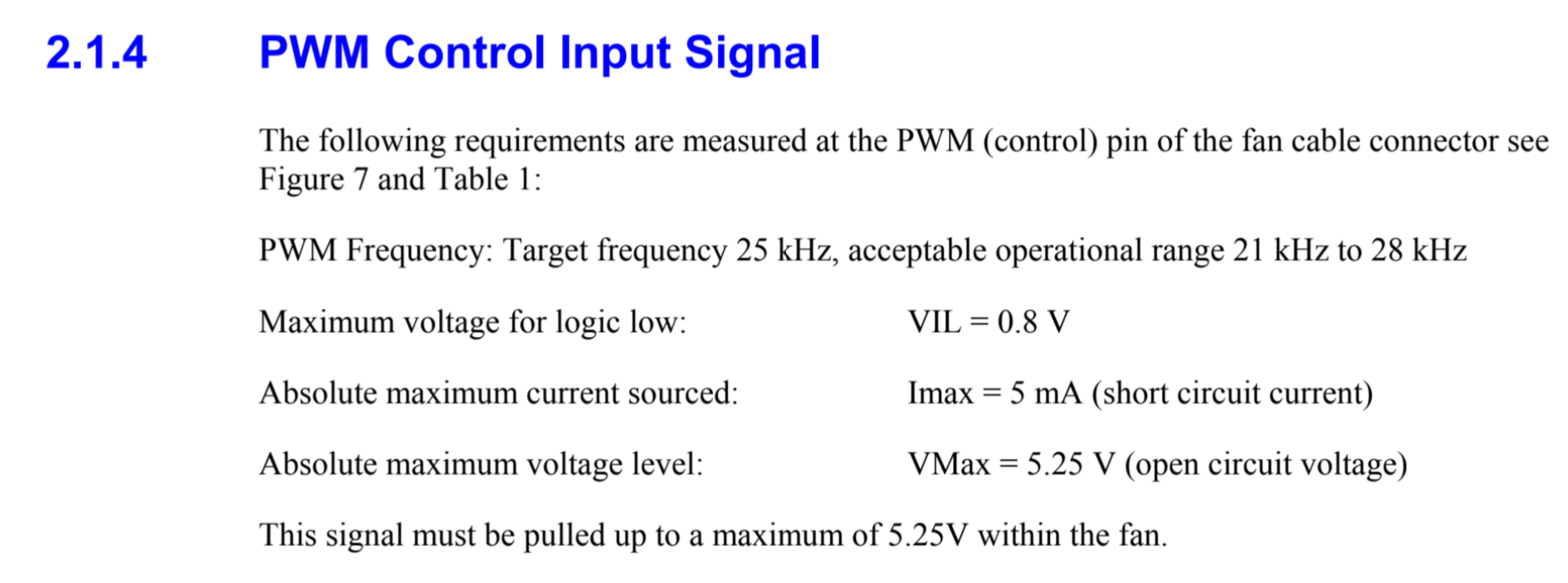
Anforderungen an ein PWM-Steuersignal
2.1.4 PWM Control Input Signal The following requirements are measured at the PWM (control) pin of the fan cable connector see Figure 7 and Table 1: PWM Frequency: Target frequency 25 kHz, acceptable operational
in „ESP, N-Mosfet 12V Fan PWM mit Mos-Modul“ · Analoge Elektronik und Schaltungstechnik · · Screenshots

-
 Bild
Bild
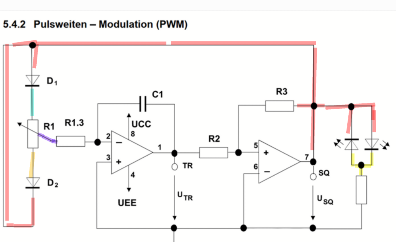
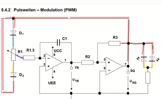
Schaltplan einer PWM-Schaltung
5.4.2 Pulsweiten – Modulation (PWM) D1 R1 R1.3 2 3 4 C1 8 1 UCC UEE UTR R2 5 6 R3 7 SQ USQ
in „Operationsverstärker Schaltung auf Steckbrett“ · Analoge Elektronik und Schaltungstechnik · · Schaltpläne
-
 Bild
Bild
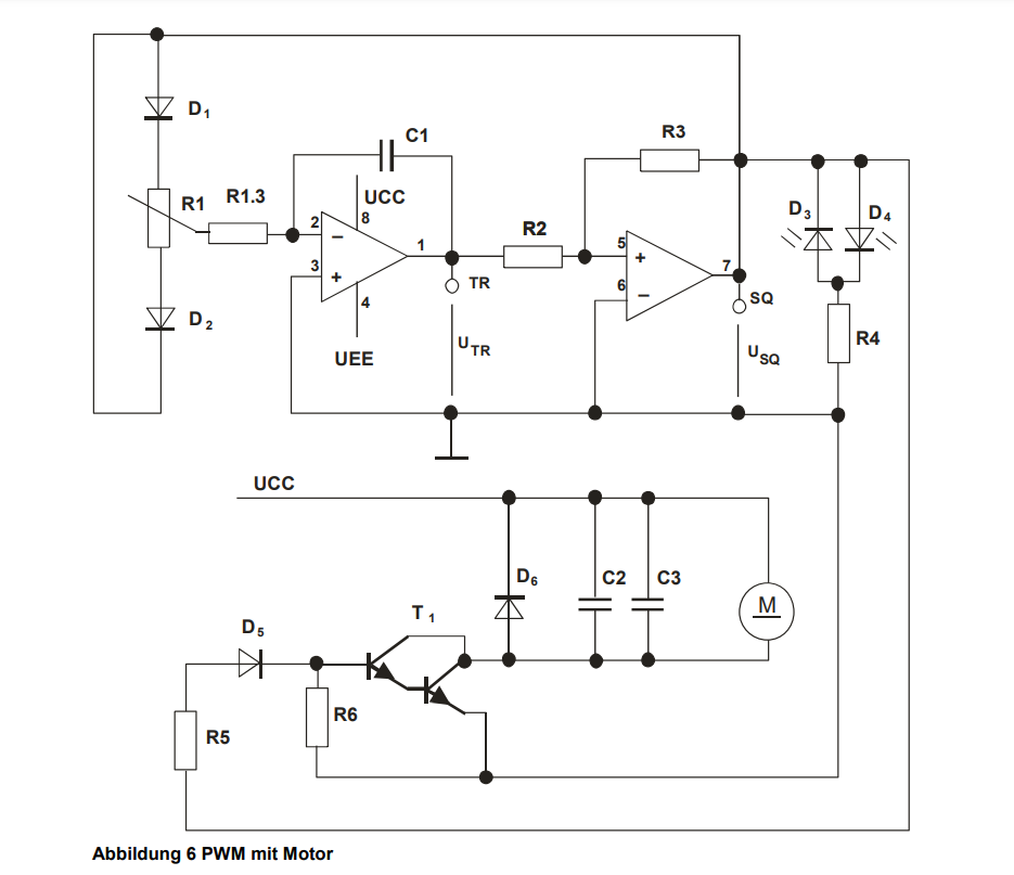
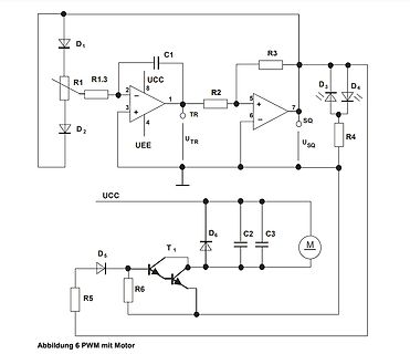
Schaltplan einer PWM-Motorsteuerung
1, TR, UTR, R2, 5, +, 7, R3, D3, D4, SQ, USQ, R4, UCC, D6, C2, C3, M, D5, R5, R6, T1, Abbildung 6 PWM mit Motor
in „Operationsverstärker Schaltung auf Steckbrett“ · Analoge Elektronik und Schaltungstechnik · · Schaltpläne
-
 Bild
Bild
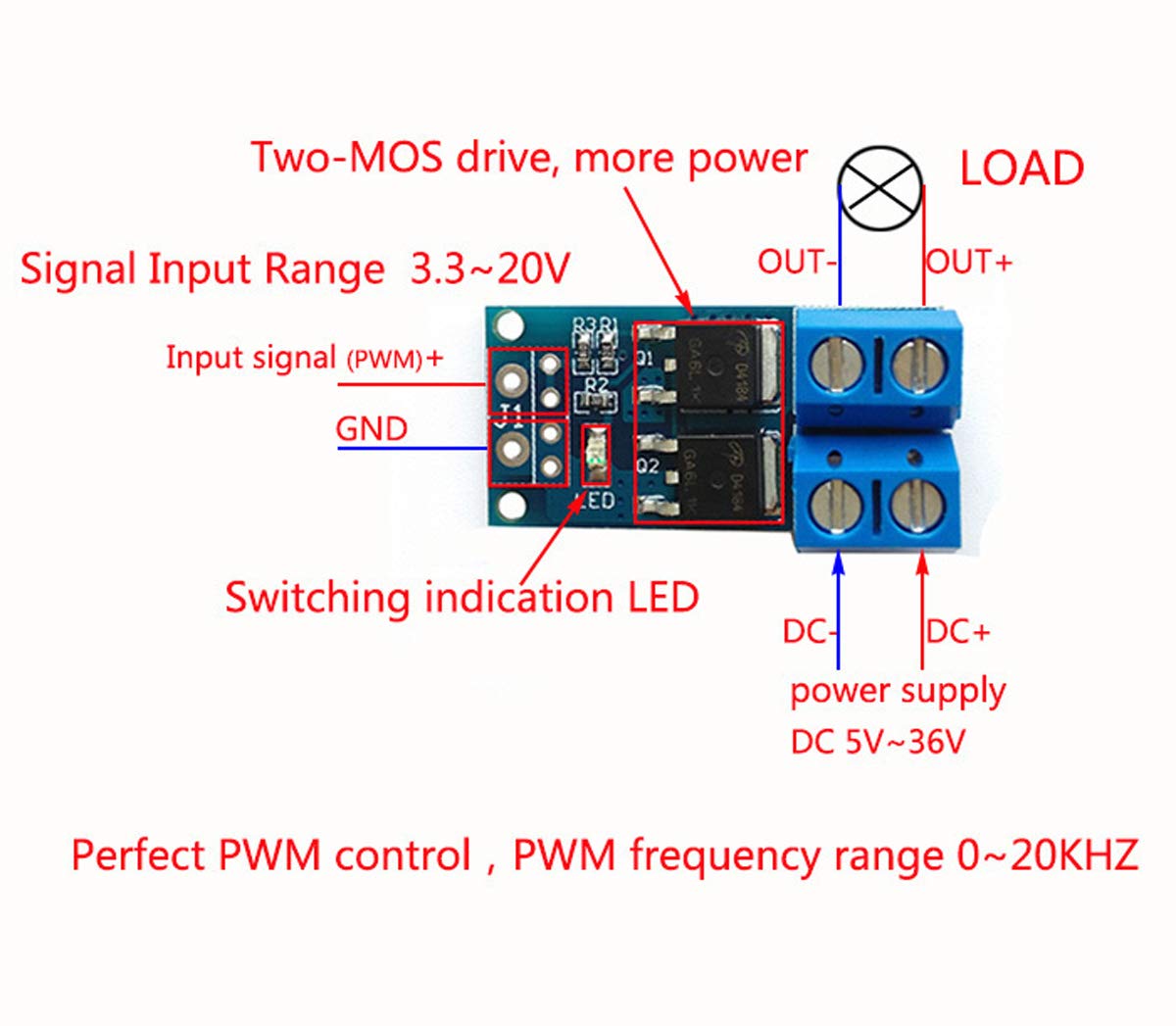
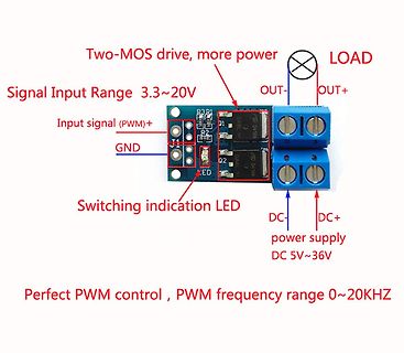
PWM-Leistungsmodul mit Beschriftung
Two-MOS drive, more power LOAD OUT- OUT+ Signal Input Range 3.3~20V Input signal (PWM)+ R2 R1 GND 01 02 Switching indication LED DC- DC+ power supply DC 5V~36V Perfect PWM control, PWM frequency range 0~20KHZ
in „Einfache Schaltung - wie?“ · Analoge Elektronik und Schaltungstechnik · · Platinenfotos
-
 Bild
Bild
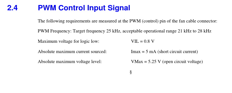
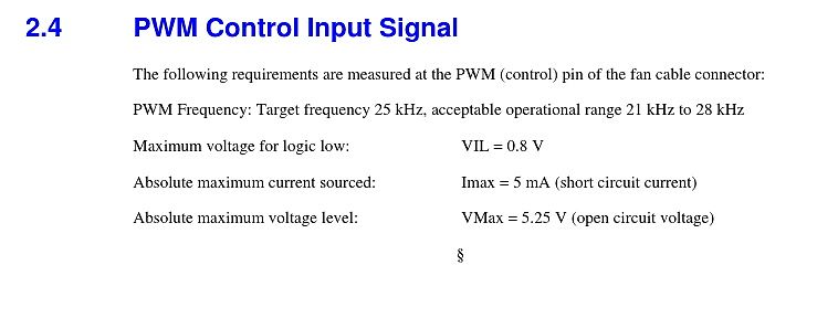
Anforderungen an ein PWM-Steuersignal
2.4 PWM Control Input Signal The following requirements are measured at the PWM (control) pin of the fan cable connector: PWM Frequency: Target frequency 25 kHz, acceptable operational range 21 kHz to 28 kHz
in „4Pin luefter Spezifikation“ · Mikrocontroller und Digitale Elektronik · · Screenshots
-
 Bild
Bild
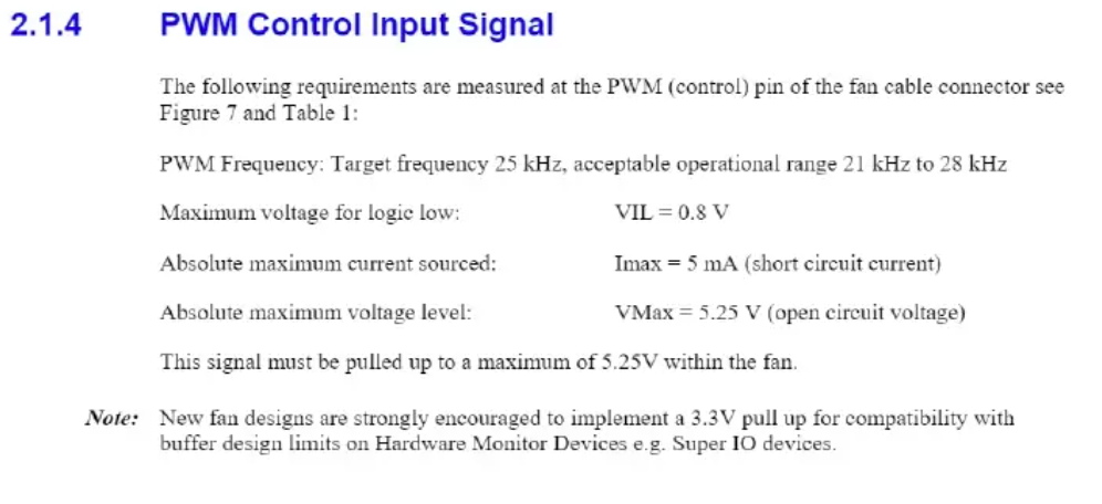
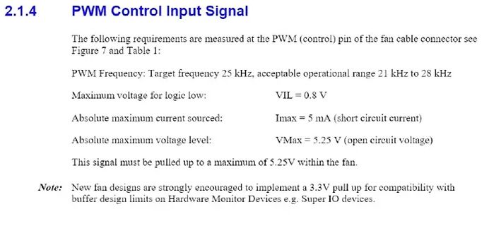
Textabschnitt zu PWM-Steuersignalspezifikationen
2.1.4 PWM Control Input Signal The following requirements are measured at the PWM (control) pin of the fan cable connector see Figure 7 and Table 1: PWM Frequency: Target frequency 25 kHz, acceptable operational
in „4Pin luefter Spezifikation“ · Mikrocontroller und Digitale Elektronik · · Screenshots
-
Datei
main.c
-*/ #include "main.h" #include "stm32l4xx_hal.h" /* USER CODE BEGIN Includes */ #define TIM_OCMODE_PWM2_CH1 TIM_OCMODE_PWM2 #define TIM_OCMODE_PWM2_CH2 ((uint32_t)TIM_CCMR1_OC2M_2 | TIM_CCMR1_OC2M_1 | TIM_CCMR1_OC2M_0) #define TIM_OCMODE_PWM2_CH3 ((uint32_t)TIM_CCMR2_OC3M_2 | TIM_CCMR2_OC3M_1 | TIM_CCMR2
in „PWM Signalerzeugung“ · Mikrocontroller und Digitale Elektronik ·
-
Datei
absolute_beginner_6.c
************* DDRD = 0xff; // PortD Ausgänge DDRC = 0x00; // PortC Eingänge // **** Einrichten von PWM Betrieb *************************************************************** // Der Timer 0 wird im Fast PWM Modus betrieben TCCR0A = ((1 <<WGM01)|(1<<WGM00)) ;// waveform generation mode auf "Fast PWM"
in „Motor ansteuern mit Atmega8“ · Mikrocontroller und Digitale Elektronik ·
-
Datei
PIV-Sequenzer.c
toggle_operation_laser_1(void){ if (status.laser_1){ /* Wenn aus: - Poti auslesen - Wert berechnen und PWM einstellen - Display: "Laserleistung / xx%" - PWM für PB1 einschalten - status.laser_1 = 1 */ } else{ /* Wenn an: - PWM für PB1 ausschalten - status.laser_1 = 0 - ins Menü zurückspringen -> update_display
in „Mega8: Ausgang an Port D verhindert Displayanzeige per TWI an Port C“ · Mikrocontroller und Digitale Elektronik ·
-
Datei
my_menu.h
define MENU_MIN_RESISTOR _MENU_MIN_RESISTOR #define MENU_MAX_RESISTOR _MENU_MAX_RESISTOR #define MENU_PWM_FREQ _MENU_PWM_FREQ #define MENU_PWM_DUTY_CYCLE _MENU_PWM_DUTY_CYCLE #define MENU_SET_MIN_VOLTAGE _MENU_SET_MIN_VOLTAGE #define MENU_ZURUECK _MENU_ZURUECK #define MENU_SET_VAL _MENU_SET_VAL #define
in „Menü - Array in Struct“ · Mikrocontroller und Digitale Elektronik ·
-
Datei
noname1.bas
$crystal = 9600000 $hwstack = 16 $swstack = 5 $framesize = 16 Config Portb.0 = Output 'Ausgang f?r PWM an PB0 Config Timer0 = Pwm , Compare A Pwm = Clear Down , Prescale = 1 Config 1wire = Portb.4 'hier ist der DS18S20 angeschlossen 'Dimensionierung der Variablen: Dim Variable1 As Byte Dim Variable2
in „Bascom vs. Assembler“ · Mikrocontroller und Digitale Elektronik ·
-
Datei
Programm.c
Match Ausgang auf LOW) |(0<<COM1B0) |(1<<WGM11) //FAST PWM mit TOP durch ICR1 und Compare durch OC1B |(0<<WGM10); TCCR1B = (1<<WGM13) //FAST PWM mit TOP durch ICR1 und Compare durch OC1B | (1<<WGM12) | (0<<CS12) | (1<<CS11) | (0<<CS10); // Prescale 8 TIMSK1
in „ADC Auto-Trigger mit Timer1 Compare Match B“ · Mikrocontroller und Digitale Elektronik ·
-
Datei
SOFTPWM.txt
reset: ;Stackpointer initialisieren: ldi wl,low(ramend) out SPL,wl ldi wl,high(ramend) out SPH,wl ;PWM-Ausgänge (LEDs) initialisieren: ldi wl, 0xff ;Port für LEDs (PWM-Ausgänge) out lep-1,wl ;= Ausgang (DDRx=PORTx-1) ;Tasten-Eingänge initialisieren: ldi wl, alltast ;pull-ups für Tasten out tap+2,wl ;
in „PWM IM SRAM MEGA8515“ · Mikrocontroller und Digitale Elektronik ·
-
Datei
PCA9635.c
0x00(0) for( i = 0; i < NR_LEDS; i++ ) LED[i] = 0x00; //LED_OFF: LED_OFF = 0x00; //Reg 0x12 - Group PWM - Variablen GROUP_PWM = 0xFF; //Reg 0x13 - Group Freq - Variablen GROUP_FREQ = 0x00; //Reg 0x14-0x17 - LED Output State Control - Variablen for( i = 0; i < 1 + NR_LEDS / 8; i++ ) LED_OUTPUT[i] = 0xAA
in „Funktion funktionieren nicht aber warum?“ · Mikrocontroller und Digitale Elektronik ·
-
Datei
Bruno_Timer1_Pulsformen.ino
deleteTimer1Mode(); switch (mode) { case 0 : ; break; // Normal case 1 : TCCR1A |= _BV(WGM10); break; // PWM, Phase Correct 8-Bit case 2 : TCCR1A |= _BV(WGM11) ; break; // PWM, Phase Correct 9-Bit case 3 : TCCR1A |= _BV(WGM11) | _BV(WGM10); break; // PWM, Phase Correct 10-Bit case 4 : TCCR1B |= _BV(WGM12); ; break; // CTC, OCRnA case 5 : TCCR1B |= _BV(WGM12); TCCR1A |= _BV(WGM10); break; // Fast PWM 8 Bit case 6 : TCCR1B |= _BV(WGM12); TCCR1A |= _BV(WGM11) ; break; // Fast PWM 9 Bit case 7 : TCCR1B |= _BV(WGM12); TCCR1A |= _BV(WGM11) | _BV(WGM10); break; // Fast PWM 10 Bit case 8 : TCCR1B |= _BV
in „Präzise Pulse aus Arduino Leonardo“ · Mikrocontroller und Digitale Elektronik ·
-
PDF
LMD18200.pdf
2 L X H NONE Application Information TYPES OF PWM SIGNALS The LMD18200 readily interfaces with different forms of PWM signals. Use of the part with two of the more popular DS010568-5 forms of PWM is described in the following paragraphs. FIGURE 3.
in „Halbbrücke für BLDC“ · Mikrocontroller und Digitale Elektronik ·
-
Datei
main.c
... //+++ pwm +++ uint32_t cycle = 150000; uint16_t offsetx[8]={1,4,8,16,32,50,300,15000}; u8 ozl=5,ozlmult=10; if ( PWM_Init( CHANNEL_NUM, 0 ) != TRUE ){while( 1 ); } pwm1_clk_sel = (PCLKSEL0>>12)&3; lgi(9,1,pwm1_clk_sel); PWM_Start( CHANNEL_NUM ); PWM_Set( CHANNEL_NUM, cycle, offsetx[ozl]*ozlmult ); //--- pwm --- .... u8 tast1=1,tast1alt=1,pulse_an=2,automatik=0; u32 adval=0; //++++++++++ while ++++++++++++++ while(1) {
in „Nähmaschine, Umbau auf Phasenanschnittsteuerung“ · Analoge Elektronik und Schaltungstechnik ·
-
Datei
main.c
Author: Ingo */ #include "main.h" #include "Funktionen.h" #include "Sin_Tab.h" volatile unsigned int PWM_Buffer_1 = 0; volatile unsigned int PWM_Buffer_2 = 0; volatile unsigned int PWM_Buffer_3 = 0; volatile unsigned int f_soll = 30; int main (void) { Init_AVR(); while(1){ // Nothing to Do ;) } return
in „Variable decementieren“ · Mikrocontroller und Digitale Elektronik ·
-
Datei
main.c
1024: 1 - 0 - 1 TCCR0B &=~ (1<<CS00); TCCR0B |= (1<<CS01); TCCR0B &=~(1<<CS02); OCR0A=1; } void set_pwm(uint8_t pwm) { if(pwm>0) { initpwm(); OCR0A=pwm; } else { TCCR0A=0; PORTB&=~(1<<LEDROT); } } int main(void) { ACSR|=(1<<ACD); // Stromsparmaßnahme DDRB=0x05; // Ports 0 und 2 als Ausgang PORTB|=(1<<
in „attiny84 und seltsame Taster-Verzögerung“ · Mikrocontroller und Digitale Elektronik ·
-
Datei
uc3a1512.h
AVR32_PWM_CHANNEL_LENGTH 0x7 #define AVR32_PWM_LINES_MSB 6 #define AVR32_PWM_0_PIN 51 #define AVR32_PWM_0_FUNCTION 0 #define AVR32_PWM_1_PIN 52 #define AVR32_PWM_1_FUNCTION 0 #define AVR32_PWM_2_PIN 53 #define
in „Registernamen AT32UC3A1512“ · Mikrocontroller und Digitale Elektronik ·
-
PDF
LGT8FX8P_databook_v1.0.4.pdf
ACOoutput ACOAfter Filter 比较器输出滤波时序 AC0 的数字滤波通过 C0XR 寄存器的 C0FEN 以及 C0FS 位控制,具体设置方式请参考本章 寄存器定义部分。 比较器输出与 PWM 控制 LGT8FX8P 支持多通道 PWM 输出,PWM 信号可以与比较器模块配合使用。比较器的输 出,可用于直接关断 PWM 信号,从而实现比较灵活的 PWM 保护方案。 与 PWM 输出相关的控制,请参考定时器章节的相关部分。 - 220 - LGT8FX8P Series – Programming Manual 1.0.4 LogicGreen Technologies Co., LTD
in „Spot Welder Firmware Update fehlerhaft“ · Mikrocontroller und Digitale Elektronik ·
-
PDF
LGT8FX8P_databook_v1.0.4.pdf
ACOoutput ACOAfter Filter 比较器输出滤波时序 AC0 的数字滤波通过 C0XR 寄存器的 C0FEN 以及 C0FS 位控制,具体设置方式请参考本章 寄存器定义部分。 比较器输出与 PWM 控制 LGT8FX8P 支持多通道 PWM 输出,PWM 信号可以与比较器模块配合使用。比较器的输 出,可用于直接关断 PWM 信号,从而实现比较灵活的 PWM 保护方案。 与 PWM 输出相关的控制,请参考定时器章节的相关部分。 - 220 - LGT8FX8P Series – Programming Manual 1.0.4 LogicGreen Technologies Co., LTD
-
Datei
lipo_charge_V0.90.c
prescaler (12V -> 2000mV; 15mV -> 2.5mV/bit) * - CH1 - current with (5A -> 2500mV; 5mA -> 2.5mV/bit) * - PWM - high-active output to buckconverter */ #define CH0 PORTC0 //Strommesspunkt #define CH1 PORTC1 //Spannungsmesspunkt #define PWM PORTB1 //PWM #define NOP asm volatile ("nop") #define MOD_WAITING 0x00
in „if-else-Schleife in if-Schleife geht nicht?“ · Mikrocontroller und Digitale Elektronik ·
-
Datei
8pwm2.2.txt
;Demoprogramm für 8-fach-PWM mit Tastensteuerung und Pollin-LCD 4x27. ;8 LEDs gegen Vcc an Port B (STK500) ;4 entprellte Tasten gegen GND für die einzelnen PWM-Kanäle an Port C ;Davon 2 Tasten (Dimm-Tasten) mit Repeat-Funktion
in „MENÜ-STEUERUNG“ · Mikrocontroller und Digitale Elektronik ·
-
Datei
8pwm2.3.txt
;Demoprogramm für 8-fach-PWM mit Tastensteuerung und Pollin-LCD 4x27. ;8 LEDs gegen Vcc an Port B (STK500) ;4 entprellte Tasten gegen GND für die einzelnen PWM-Kanäle an Port C ;Davon 2 Tasten (Dimm-Tasten) mit Repeat-Funktion
in „MENÜ-STEUERUNG“ · Mikrocontroller und Digitale Elektronik ·
-
Datei
wiring.c
overflow interrupt not set correctly #endif // timers 1 and 2 are used for phase-correct hardware pwm // this is better for motors as it ensures an even waveform // note, however, that fast pwm mode can achieve a frequency of up // 8 MHz (with a 16 MHz clock) at 50% duty cycle #if defined(TCCR1B) &&
in „IRMP - Infrared Multi Protocol Decoder“ · Projekte & Code ·
-
Datei
Motor1.c
7 (Fast PWM) (Aus Tabelle 14-8) TCCR0B |= (1<<WGM02); //Mode 7 (Fast PWM) (Aus Tabelle 14-8) TCCR0B |= ((0<<CS02) | (0<<CS01) | (1<<CS00)); //Kein Teiler (Aus Tabelle 14-9) OCR0A=100; //Top-Wert von timer0 /*Zwei
in „zwei if-Anweisungeg funktionieren nicht zusammen“ · Mikrocontroller und Digitale Elektronik ·
-
PDF
tlc59108.pdf
02h PWM0 7:0 IDC0[7:0] R/W 0000 0000(2) PWM0 individual duty cycle 03h PWM1 7:0 IDC1[7:0] R/W 0000 0000(2) PWM1 individual duty cycle (2) 04h PWM2 7:0 IDC2[7:0] R/W 0000 0000 PWM2 individual duty cycle 05h PWM3 7:0 IDC3[7:0] R/W 0000 0000(2) PWM3 individual duty cycle (2) 06h PWM4 7:0 IDC4[7:0] R/W 0000 0000 PWM4 individual duty cycle 07h PWM5 7:0 IDC5[7:0] R/W 0000 0000(2) PWM5 individual duty cycle 08h
in „[V] 4St. LED Treiber TI - TLC59108 8-Bit Fm+ I2C-Bus Constant-Current LED Sink Driver“ · Markt ·
-
Datei
lightshow.vhd
pattern20 + pattern21 signal cnt1,cnt20, cnt21 : std_logic_vector(22 downto 0) := (others => '0'); signal pwm_cnt : std_logic_vector(19 downto 0) := (others => '0'); signal pwm_cnt8 : std_logic_vector(7 downto 0) := (others => '0'); begin pwm_cnt8 <= pwm_cnt(19 downto 12); dp_fxclk: process(fxclk) begin if
in „freehdl, components, ambiguousness“ · FPGA, VHDL & Co. ·
-
PDF
atmel_32uc.pdf
GPIO 49 MACB - RX_CLK USB - USB_VBOF EBI - ADDR[23] 99 141 PB18 GPIO 50 MACB - SPEED ADC - TRIGGER PWM - PWM[6] 100 143 PB19 GPIO 51 PWM - PWM[0] PM - GCLK[0] EIM - SCAN[4] 1 3 PB20 GPIO 52 PWM - PWM[1] PM - GCLK[1] EIM - SCAN[5] 2 5 PB21 GPIO 53 PWM - PWM[2] PM - GCLK[2] EIM - SCAN[6] 3 6 PB22 GPIO
in „V: ATMEL 32UC3A0512-U“ · Markt ·
-
PDF
1932f.pdf
the LED brightness varies linearly with the range (greater than20:1) by pulsingthe LEDs onandoff PWM duty cycle. usingthecontrolsignal.TheLEDsoperateateitherzeroor full current, but their average current changes with the PWMsignal duty cycle. Typically, a 5kHz to 40kHz PWM signal is used. PWM dimming
in „step up converter 3,6V -> 8 LED's“ · Mikrocontroller und Digitale Elektronik ·
-
PDF
LT1932.pdf
the LED brightness varies linearly with the range (greater than20:1) by pulsingthe LEDs onandoff PWM duty cycle. usingthecontrolsignal.TheLEDsoperateateitherzeroor full current, but their average current changes with the PWMsignal duty cycle. Typically, a 5kHz to 40kHz PWM signal is used. PWM dimming
in „IC LED Ansteuerung LTST“ · Analoge Elektronik und Schaltungstechnik ·
-
PDF
Anleitung_PowerLog6S_DE.pdf
Einstellbereich ange- zeigt. Bei einer evtl. Anpassung des Bereichs werden fehler- hafte Vorgaben gemeldet: PWM SETTING > PWM Ad- justable Range Settings 2. Automatische Einstellung der PWM-Signale Um PWM-Ausgangssignale automatisch einzustellen, navigieren Sie bitte zum Menü ’Auto’ und betätigen Sie >, das Display
in „TRXCharger Ladekurve mit LogView ansehen“ · Mikrocontroller und Digitale Elektronik ·
-
PDF
LMD18200_-_HBr__cke.pdf
to PWM input, pin Sign/magnitude PWM consists of separate direction (sign) 5. The drivers that short the motor are determined by the and amplitude (magnitude) signals. The (absolute) magni- logic level at
in „LMD18200 current sense Charakteristik. Erfahrung?“ · Analoge Elektronik und Schaltungstechnik ·