User's manual Attaching Procedure (1) Attach the compact emulator or emulation probe to the EMULATOR side of the M3T-F160-EXTC. (2) Attach the converter board to the TARGET side of the M3T-F160-EXTC. Usage [Ordering Information] See Appendix H "Ordering Information". *All brand names and product names are
from a Hobby Shop. This filter is “semi-ugly.” That is, it is a breadboard, but has a pattern on the side of the board containing the components. This was cut by hand. The other side serves as the circuit ground. Fig 6. Outside view of “Filter 1.” The coax connectors and the trimmer capacitor terminals can be seen sticking through the board. The wires are connections to grounded foils on the other side of the board where brass walls reside. Filter #2 was similar. The inductors were like those used in the first filter. However, plastic insulation trimmer capacitors were used with completely ugly construction
amounts of cur- P rent. Figure 4 shows the measured effect of an adjacent current trace on the same side of the PCB as the device.Although this is a consideration for Magnetic Flux Induced by Current Flow Figure 2. U-Loop and Hall Element. Current flowing through the U-loop generates flux lines in planes
connector uses a standard IEEE-488 pinout. Back view 2 3 (2) Status LED (3) Firmware update button Side view 4 (4) USB-Type C connector – plug it with either a USB Type C to USB type A or USB type C to type C cable into your PC. Page | 5 LED The LED has multiple purposes as summarized in the table below
oscillations and have been known to cause device failures. A transient can get to the gate from the drive side or from the drain side. In either case, it would be an indication of a more fundamental problem: a high impedance drive circuit. A zener would compound this problem, rather than solving it. Sometimes
either nRESET pin is applied, or VM is removed and reapplied. Overcurrent conditions on both high-side and low-side devices; that is, a short to ground, supply, or across the motor winding all result in an overcurrent shutdown. Note that overcurrent protection does not use the current sense circuitry
SOURCE (HV RTN) Y package – Output MOSFET source connection for high voltage power return. Primary side circuit SOURCE 3 6 SOURCE (HV RTN) common and reference point. CONTROL 4 5 DRAIN P and G package – Primary side control circuit common and DIP-8 (P08A) reference point. SMD-8 (G08A) PI-2084-052198 SOURCE
CRITERIA • SOLDER WETS 3 SIDES OF TERMINAL, BUT LESS THAN 25% OF SIDES AND FRONT SURFACE AREA ARE COVERED SOLDER (3)PARTS ALIGMENT (a)LSI, IC LEAD WIDTH IS MORE THAN 50% BEYOND PAD 13. SOLDERING OUTLINE (b)CHIP COMPONENT COMPONENT
LOWER BEND OR “HEEL” OF LEAD AND PAD SOLDER FILLET (b)CHIP COMPONENT . SOLDER IS LESS THAN 50% OF SIDES AND FRONT FACE WETTING SOLDER FILLET 1/2 • SOLDER WETS 3 SIDES OF TERMINAL, BUT LESS THAN 25% OF 12. SOLDERING SIDES AND FRONT SURFACE AREA ARE COVERED SOLDER (3)PARTS ALIGMENT (a)LSI, IC LEAD WIDTH
LOWER BEND OR “HEEL” OF LEAD AND PAD SOLDER FILLET (b)CHIP COMPONENT . SOLDER IS LESS THAN 50% OF SIDES AND FRONT FACE WETTING SOLDER FILLET 1/2 • SOLDER WETS 3 SIDES OF TERMINAL, BUT LESS THAN 25% OF 12. SOLDERING SIDES AND FRONT SURFACE AREA ARE COVERED SOLDER (3)PARTS ALIGMENT (a)LSI, IC LEAD WIDTH
0.355 0.365 0.400 3 b2 L D1 0.005 – – 3 b3 E 0.300 0.310 0.325 4 4 PLCS b E1 0.240 0.250 0.280 3 Side View e 0.100 BSC eA 0.300 BSC 4 L 0.115 0.130 0.150 2 Notes: 1. This drawing is for general information only; refer to JEDEC Drawing MS-001, Variation BA, for additional information. 2. Dimensions A
LOWER BEND OR “HEEL” OF LEAD AND PAD SOLDER FILLET (b)CHIP COMPONENT . SOLDER IS LESS THAN 50% OF SIDES AND FRONT FACE WETTING SOLDER FILLET 1/2 • SOLDER WETS 3 SIDES OF TERMINAL, BUT LESS THAN 25% OF 12. SOLDERING SIDES AND FRONT SURFACE AREA ARE COVERED SOLDER (3)PARTS ALIGMENT (a)LSI, IC LEAD WIDTH
LOWER BEND OR “HEEL” OF LEAD AND PAD SOLDER FILLET (b)CHIP COMPONENT . SOLDER IS LESS THAN 50% OF SIDES AND FRONT FACE WETTING SOLDER FILLET 1/2 • SOLDER WETS 3 SIDES OF TERMINAL, BUT LESS THAN 25% OF 12. SOLDERING SIDES AND FRONT SURFACE AREA ARE COVERED SOLDER (3)PARTS ALIGMENT (a)LSI, IC LEAD WIDTH
LOWER BEND OR “HEEL” OF LEAD AND PAD SOLDER FILLET (b)CHIP COMPONENT . SOLDER IS LESS THAN 50% OF SIDES AND FRONT FACE WETTING SOLDER FILLET 1/2 • SOLDER WETS 3 SIDES OF TERMINAL, BUT LESS THAN 25% OF 12. SOLDERING SIDES AND FRONT SURFACE AREA ARE COVERED SOLDER (3)PARTS ALIGMENT (a)LSI, IC LEAD WIDTH
SOURCE (HV RTN) Y package – Output MOSFET source connection for high voltage power return. Primary side circuit SOURCE 3 6 SOURCE (HV RTN) common and reference point. CONTROL 4 5 DRAIN P and G package – Primary side control circuit common and P Package (DIP-8) reference point. G Package (SMD-8) PI-2084
LOWER BEND OR “HEEL” OF LEAD AND PAD SOLDER FILLET (b)CHIP COMPONENT . SOLDER IS LESS THAN 50% OF SIDES AND FRONT FACE WETTING SOLDER FILLET 1/2 • SOLDER WETS 3 SIDES OF TERMINAL, BUT LESS THAN 25% OF 12. SOLDERING SIDES AND FRONT SURFACE AREA ARE COVERED SOLDER (3)PARTS ALIGMENT (a)LSI, IC LEAD WIDTH
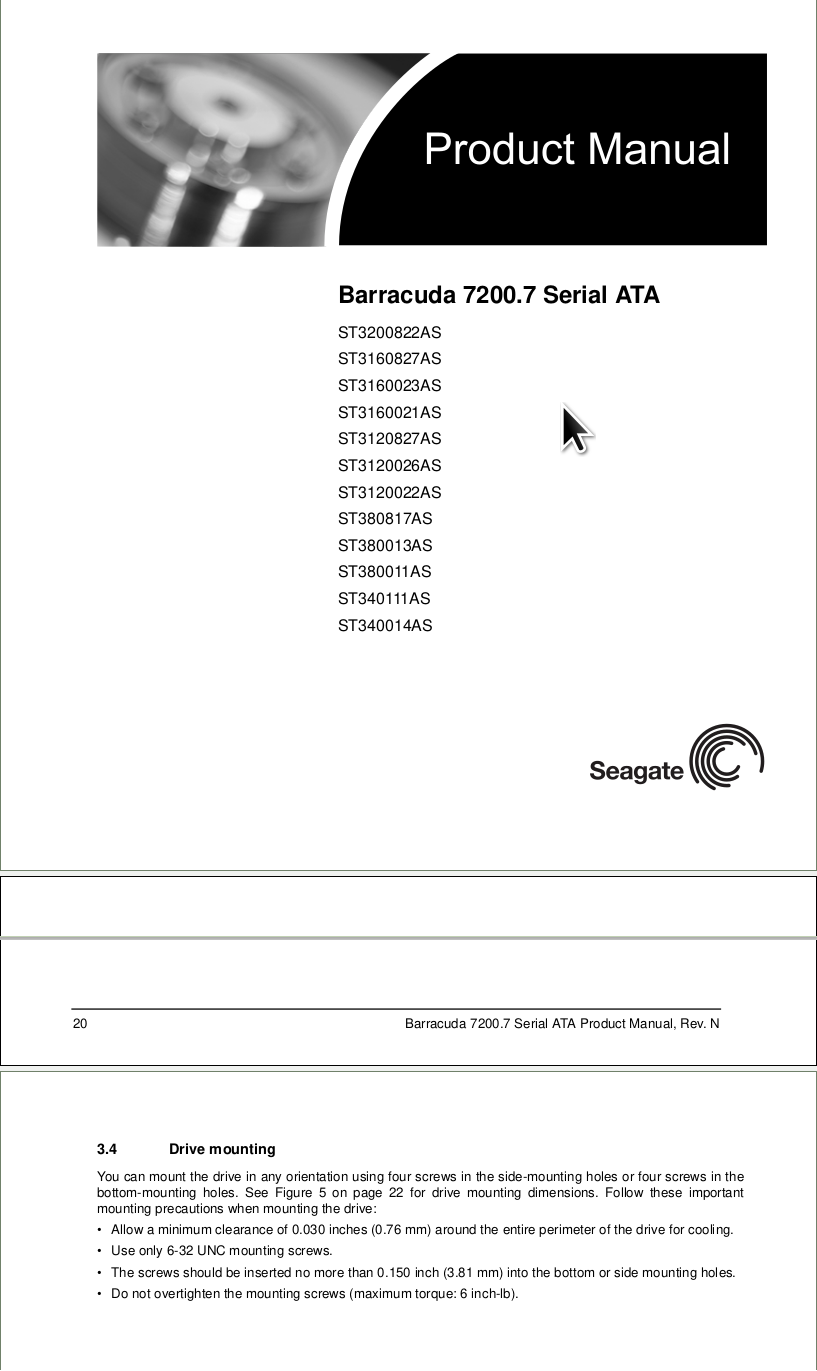
Manual, Rev. N
3.4 Drive mounting
You can mount the drive in any orientation using four screws in the side-mounting holes or four screws in the bottom-mounting holes. See Figure 5 on page 22 for drive mounting dimensions. Follow these important mounting precautions when mounting the drive:
• Allow a minimum
in Figure 13, derived artificially from a ramp generator, as with the inductor is on the secondary side. But since the Figure 13. - Peak Current Mode Control 5-15 Control Loop Cookbook control IC is on the primary side, it is easier to tendency to oscillate (or a full-blown oscillation) at sense primary-side
2 Absolute maximum ratings
Parameter Symbol Values Unit Note / Test Condition
Power supply output side VCC2 Min. -0.3 Max. 40 V 1)
Gate driver output VOUT GND2-0.3 VCC2+0.3 1)
Positive power supply input side VCC1 Min. -0.3 Max. 18.0 V -
Logic input voltages (IN+, IN-) VLogicIN Min. -0.3 Max. 18.0 V
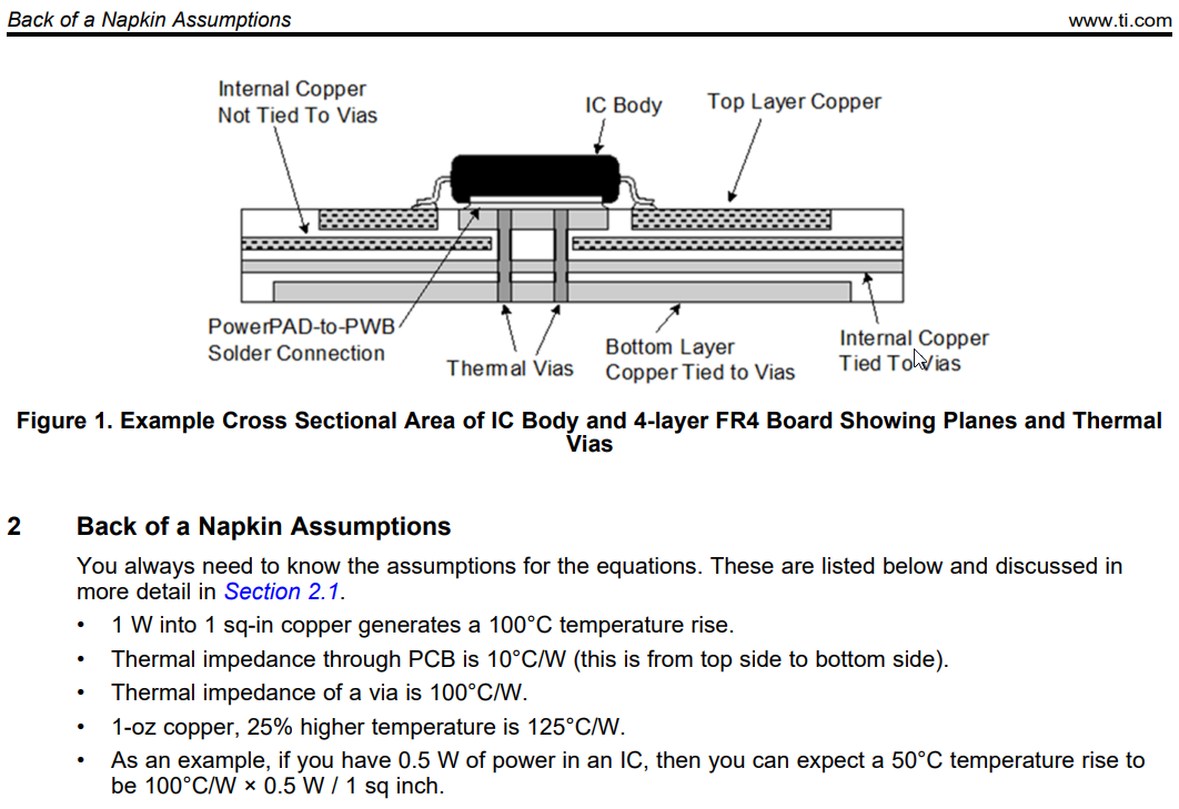
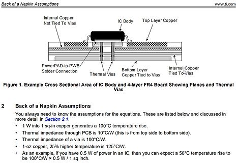
copper generates a 100°C temperature rise.
• Thermal impedance through PCB is 10°C/W (this is from top side to bottom side).
• Thermal impedance of a via is 100°C/W.
• 1-oz copper, 25% higher temperature is 125°C/W.
• As an example, if you have 0.5 W of power in an IC, then you can expect a 50°C temperature
calibration to be made in practically any application. In Figure 3, the switch is used to disconnect one side of the bridge from the amplifier and short the amplifier inputs together. Leaving the other side of the bridge connected to the input of the amplifier maintains the common-mode input voltage, thus eliminating
1 Yes No No No 0006 5AAYA93E++08 COVER FRONT ASSY 1 1 No Yes Yes Yes 0007 5MVB851SH003 COVER REAR SIDE 1 1 Yes Yes Yes Yes 0008 5MVB885CH004 COVER RIGHT 1 Yes Yes Yes Yes 0010 5MVB875CH001 COVER FRONT 1 Yes No No No 0011 5MVX422DN005 HINGE FRONT L 1 Yes Yes Yes Yes 0012 5MVX422DN006 HINDE FRONT R 1 Yes
RecommendedoperatingconditionsofCIPOS™NanoIRSM005-800MH Symbol Description Min Typ Max Unit VB HighSide FloatingSupplyVoltage VS+10 VS+15 VS+20 V VS HighSide FloatingSupplyOffsetVoltage Note1 -- 100 V VCC LowSide andLogicfixedSupplyVoltage 10 15 20 V LIN LogicinputVoltage LIN,HIN COM -- VCC V HIN Highside
stepping motors used in office equipment and amusement applications. Features • Low on resistance (upper side : 0.3Ω ; lower side : 0.25Ω ; total of upper and lower : 0.55Ω ; Ta = 25°C, I = 2.5AO • Excitation mode can be set to 2-phase, 1-2 phase, W1-2 phase , or 4W1-2 phase • BiCDMOS process IC • Excitation
or AC } Output 4 (N.O.): DC or AC Output 4 (N.O.): q DC or AC Notes: 1.E : 1ower source at input side;V : InputINoltage; I : LED foFward current; I : Input curINnt;V : Load voltagL; I : Load current;LR: Current limit resistor. 2.Method of connecting the load at the output is divided into 3 types. 34
group 1 The VK41../VK81.. series gas controls are approved in d accordance with european standards. Side outlet (optional) can be fitted direct to a burner manifold. r Pilotgasconnection(whereapplicable) s DESCRIPTION M8 x 1 for 4 mm outer diameter tubing. r Pressurefeedbackconnection h The gas control
or AC } Output 4 (N.O.): DC or AC Output 4 (N.O.): q DC or AC Notes: 1.E : 1ower source at input side;V : InputINoltage; I : LED foFward current; I : Input curINnt;V : Load voltagL; I : Load current;LR: Current limit resistor. 2.Method of connecting the load at the output is divided into 3 types. 34
voltage will change the current flowing through the motor and thus the fan speed. On the right hand side of Fig. 2 the output characteristics of the MOSFET is shown. The point where the MOSFET is being operated is shown as red dot. According to the diagram the voltage across the MOSFET will be the input
voltage will change the current flowing through the motor and thus the fan speed. On the right hand side of Fig. 2 the output characteristics of the MOSFET is shown. The point where the MOSFET is being operated is shown as red dot. According to the diagram the voltage across the MOSFET will be the input
front; 2. Does not affect the relevant alignment; Notch 3. X≤1mm, Y≤1mm, N≤2. Slight defect Glass side Foreign 1. The foreign body on the side is not controlled; Slight 2. The paint pen marks on the side are not controlled; objects defect Dirty 3. Side oily note printing is not allowed. Cracks Goldfinger
on the reverse side of PCB: 74.2 mm × 74.2 mm) t Board material: FR-4 a s 4.0 Board size: 114.3 mm × 76.2 mm × 1.6 mmt i Top copper foil: Footprint and Traces, 70 μm copper. r 2 inner layers copper foil area of PCB: e
Revision 2.8 (09-30-12) SMSC CONFIDENTIAL JukeBlox Networked Media Modules – CX Series Datasheet 6.2.1 Side View of CX Module with Bottom Shield except CX870-3JB................................ 21 6.2.2 Side View of CX870 Module with Bottom Shield part number CX870-3JB only............ 22 6.3 3D V IEW OFCX870
I2C_AR_WriteRegister(2, (I2C_AR_ReadRegister(2) & 0xFE00) | (freq_kHz - 690) ); //Set Frequency //Low-Side LO Injection //R11 --> clear D15, clear D0/D2, D3 is the same as default I2C_AR_WriteRegister(11, I2C_AR_ReadRegister(11) & 0x7FFA); //Enable tune bit AR1000_TUNE_ON; //Wait for tune to stabilize (STC flag) wait_stc(); //Low-side TUNE Ends int rssi1 = ar_rssi(); AR1000_TUNE_OFF; printf(" RSSI 1 = %d", rssi1); //Read Hi-Side LO Injection // R11-->set D15, set D0/D2, D3 is the same as default I2C_AR_WriteRegister(11, I2C_AR_ReadRegister
INA138 INA168 For most current data sheet and other product information, visit www.burr-brown.com High-Side Measurement CURRENT SHUNT MONITOR DESCRIPTION FEATURES COMPLETE UNIPOLAR HIGH-SIDE The INA138 and INA168 are high-side, unipolar, CURRENT MEASUREMENT CIRCUIT current shunt monitors. Wide input common-mode
table provides the PWM Values and a dead time is inserted for driving * larger loads via high and low side drivers * due to pin restrictions we cannot have a lot of user interfacing * fuse the Tiny to 8 Mhz internal RC oscillator and no CLKDIV * * Matthias Schöldgen , June 2012 * * initially designed to
Store the products in an anti-electrostatic container. - Seiko Instruments Inc. - COGI2 Component side Link3 Component side COGI2 Solder side Link3 Solder side

 Bild
Bild
 Bild
Bild
 Bild
Bild
 Bild
Bild
 Bild
Bild

 Bild
Bild

 Bild
Bild

 Bild
Bild
 Bild
Bild
 Bild
Bild
 Bild
Bild