-
 Bild
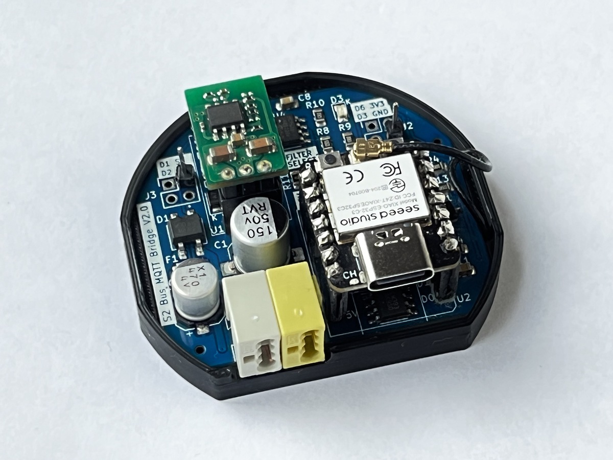
Offene Elektronikplatine mit Seeed Studio Modul
S2 Bus MQTT Bridge V2.0, C8, R10, D6 3V3, D3 GND, R8, R9, F1, Seeed studio, Model XIAO ESP32-C3, FCC CE, 150 50V, RV1, C1, C2, D1, D2, F1, <, >

-
Thread
Kleine HV Basteleien.
ja diese geringen Ströme doch direkt auf der Hochspannungsseite regeln, wenn man den Regler "Low-Side" ansetzt, damit man keine 10kV auf den Einstellpotis hat. :) Und ein toller klassischer Kabelbaum! Sogar in Schwarz gebunden, vermutlich PVC, statt wie sonst mit weißer Zahnseide. :)
-
Thread
Soundausgabe auf dem AVR
auch einen z.B. Wavetable Synthesizer auf dem AVR implementieren. Oder einen Klassiker wie den C64 SID.
-
Thread
Induktiver Positionssensor - Fragen dazu
verhindern. Im Moment ist mein Plan das als Interrupt auf den Controller zurück zu führen. Einen Low-side-switch als "Sicherung" einbauen (alles andere ist schwer zu bekommen und dann auch sehr teuer), der gleich zu Beginn eingeschaltet wird und nur durch den Interrupt oder eben durch Abschalten des Stroms
-
Thread
Suche Gehäuse für Schaltnetzteil CSP-3000
5x98mm-aluminium-ip40-elma-electronic-33e330-35/p/11035875?pos=2&origPos=2&origPageSize=50&track=false&sid=7e2b8a6f3a88c033294ac84ac9744d97fc4d7f92&itemList=pfp https://www.mouser.de/ProductDetail/Hammond-Manufacturing/1590ZGRP243?qs=%252BxyxD9GtKu0y7LJM59Ns5w%3D%3D
-
 Bild
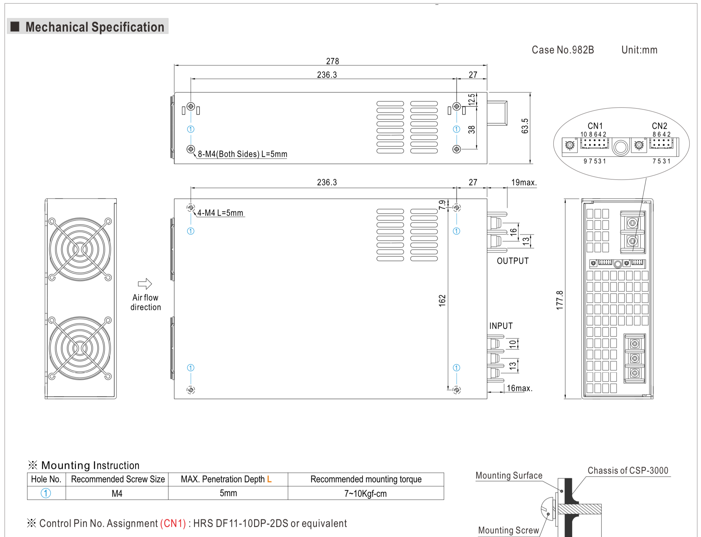
Technische Zeichnung einer Gehäuse-Mechanik
Mechanical Specification Case No.982B Unit:mm 278 236.3 27 12.5 63.5 38 8-M4(Both Sides) L=5mm CN1 10 8 6 4 2 9 7 5 3 1 CN2 8 6 4 2 7 5 3 1 236.3 27 19max. 7.9 4-M4 L=5mm 16 13 177.8 OUTPUT 162 INPUT 10 13 16max. Mounting Instruction Hole No. Recommended Screw Size MAX. Penetration Depth
-
Thread
Agilent 54832D full HDD Recovery needed
facts: Agilent 54832D SN MY5130xxxx VIN # A52 Rev. A04.20 WinXP Pro ( Licence Sticker in rear Side) Each good and helpful idea or posting is very welcome. Best regards TSei
-
Thread
Gute 3D CAD-Software für Privatanwender gesucht
://blog.freecad.org/ und hat ein super Forum .... https://forum.freecad.org/viewforum.php?f=13&sid=f39009bf9602247c2cbc4519f4ebaf5c meine Sicht der Dinge ;-)
-
Thread
Lüfter an Akku und Netzteil parallel betreiben
, dann Lüfter aus. Im ernst? Umgekehrt wäre es wohl sinnvoller. 2 N-Channel Mosfet um HighSide zu schalten? Überdenke das Ganze nochmal.
zurück in die Schaltung wegen der Diode. Und was ist an den FETs generell falsch im Bezug auf High Side schalten? Low Side wäre besser, aber da bin ich nicht auf die Lösung gekommen. Kann ich mir aber nochmal anschauen. Hoffe die Verwirrung etwas entwirrt zu haben.
-
Thread
[V] Räumungsverkauf - Alles muss weg!
Netzgerät Zustand: Gebraucht, ungeprüft, Preis: 60 VB -------------------- Ergotron LX Dual Side-by-Side Arm (45-245-224) Monitorhalterung Zustand: Wie neu, Preis: 150 VB
100 VB Meine Gewährleistung: 1 Tag NUR ABHOLUNG -------------------- Ergotron LX Dual Side-by-Side Arm (45-245-224) Monitorhalterung Zustand: Wie neu Preis: 150 VB
-
 Bild
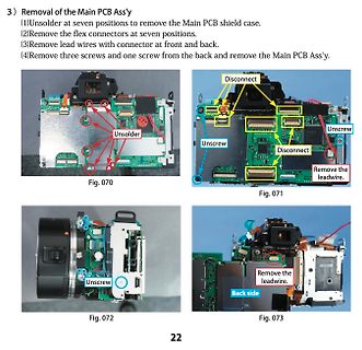
Anleitung zum Ausbau der Hauptplatine einer Kamera
Ass'y. Unsolder Disconnect Unscrew Disconnect Remove the leadwire. Unscrew Remove the leadwire. Back side Fig. 070 Fig. 071 Fig. 072 Fig. 073
-
Thread
Kühlschrank Anlaufrelais oder Kompressor defekt?
Moin, ich habe hier einen Side- by Side Kühlschrank von Quelle (privileg) stehen, der leider gerade nur ein Schrank ist. Der Kompresser läuft nicht mehr an. Ich habe inzwischen die Regelungselektronik gebrückt; der Kompressor bekommt
-
Thread
Touchscreen HITACHI TX23D12VM0CBA an Raspberry Pi anschließen
ist. https://www.waveshare.com/product/raspberry-pi/displays/lcd-oled/10.1inch-dsi-lcd-c.htm?___SID=U fchk
-
 Bild
Schaltplan eines Ethernet-Adapters für Audio-Signale
use one of the other pairs as ground (in ethernet connections they should have transformers on both sides, have they?) Sheet: / File: EthernetAdapter.kicad_sch Title: Size: A4 Date: KiCad E.A. kicad 7.0.10 Rev: Id: 1/1

-
Thread
Windows 10, Windows 11 für "Normalnutzer" ein Witz kennt wer?
Folder" nicht. Eher im Gegenteil. Da gibt es mehr Sicherheit als im "öffentlichen Bereich". Z.B. Side-Load nicht möglich, Angreifer können somit nichts installieren. Daten abgreifen geht da auch nicht.
-
Thread
Diskret aufgebauter Komparator
Hallo zusammen, ich habe eine Schaltung die wandelt einen auf der High-side gemessenen Strom in eine auf GND referenzierte Spannung um. Diese Spannung soll mit einem Sollwert (1,8V) verglichen werden. Der Strom hat die Form eines Sägezahns und eine Frequenz von 1-2MHz. Könnt
-
Thread
Bauteilmarkt: Neues auf ganzer Front
Pressemitteilung folgendermaßen beschreibt: [c] The AEC-Q102 qualified SYNIOS® P1515 LEDs produce a side-emission output with uniform 360° light intensity all round the device. Light is also emitted from the top of the LED, but at lower intensity than from the sides, to ensure that applications such as
-
 Bild
Analog Devices EVAL-CN0583-SDM Evaluation Board
ANALOG DEVICES EVAL-CN0583-SDM PRIMARY SIDE 08-068743 REV C PATENTS PENDING 28800X GND 15 28

-
Thread
ELM327 liefert NO DATA
das Steuergerät etwas mehr Zeit gönnt, daher sendet es einen (oder mehrere) BUSY NRC, z.B. via 7F <SID> 78, before die terminale Antwort kommt. Die meisten ELM327-clones können damit nicht arbeiten, ignorieren die Antworten mit Prefix 7F (weil sie in OBD2 in der Form nicht vorgesehen sind) und antworten
Steuergerät etwas mehr Zeit gönnt, daher > sendet es einen (oder mehrere) BUSY NRC, z.B. via 7F <SID> 78, before > die terminale Antwort kommt. Die meisten ELM327-clones können damit > nicht arbeiten, ignorieren die Antworten mit Prefix 7F (weil sie in OBD2 > in der Form nicht vorgesehen sind
-
Thread
DRV8711 Schrittmotortreiber Fehler
Treiber Probleme mit Eingangspannung >24V durch Rauschen. Wenn du 47 ohm Widerstände auch an die low side MOSFET Gates schaltest, könnte das Problem behoben sein.
? - 8.1.2 Optional Series Gate Resistor In high current or high voltage applications, the low side predriver fault may assert due to noise in the system. In this application, TI recommends placing a 47 to 120-Ω resistor in series with the low side output and the gate of the low side FET. TI also
-
Thread
Relaisschaltung Stromgeführt
Oder auch in Plus, Texas Instruments hat in der Typenreihe INA-xxx eine sehr große Auswahl, die high-side misst. Kann man auch mit OPs 'zu Fuß' aufbauen, nennt sich Differenzverstärker. > Spannungsabfall mit zwei Komparatoren auswerten. Ja. Klaus H. schrieb im Beitrag #7594851: > Wurden so Schaltungen
-
Thread
Esp8266 open collector mit 5V. Ist da eine schutzdiode?
Body-Diode, die auch eine Spannungbegrenzung bewirkt). Wenn du Glück hast, ist bei OpenDrain der High-Side FET (inkl Body-Diode) inaktiv ...
-
Thread
H-Brücke mit N-MosFet und 100% Duty-Cycle
Charge-Pump?)? Mit einer komplett eigenständigen GS-Versorgungsspannung (Vcc + 10V) für die High Side Mosfets, aus der endlos 100% geschöpft werden kann. Klingt aufwendiger, ist es auch. Raoul D. schrieb im Beitrag #7594329: > Oder ist es üblich, einfach nur d<=99% zu belassen? 99% ist schon
Charge-Pump?)? > > Mit einer komplett eigenständigen GS-Versorgungsspannung (Vcc + 10V) für > die High Side Mosfets, aus der endlos 100% geschöpft werden kann. Klingt > aufwendiger, ist es auch. > aufwendiger..?? mit nem isolierten preiswerten DC-DC wandler.. https://www.google.com/search?q=dc-dc
-
 Bild
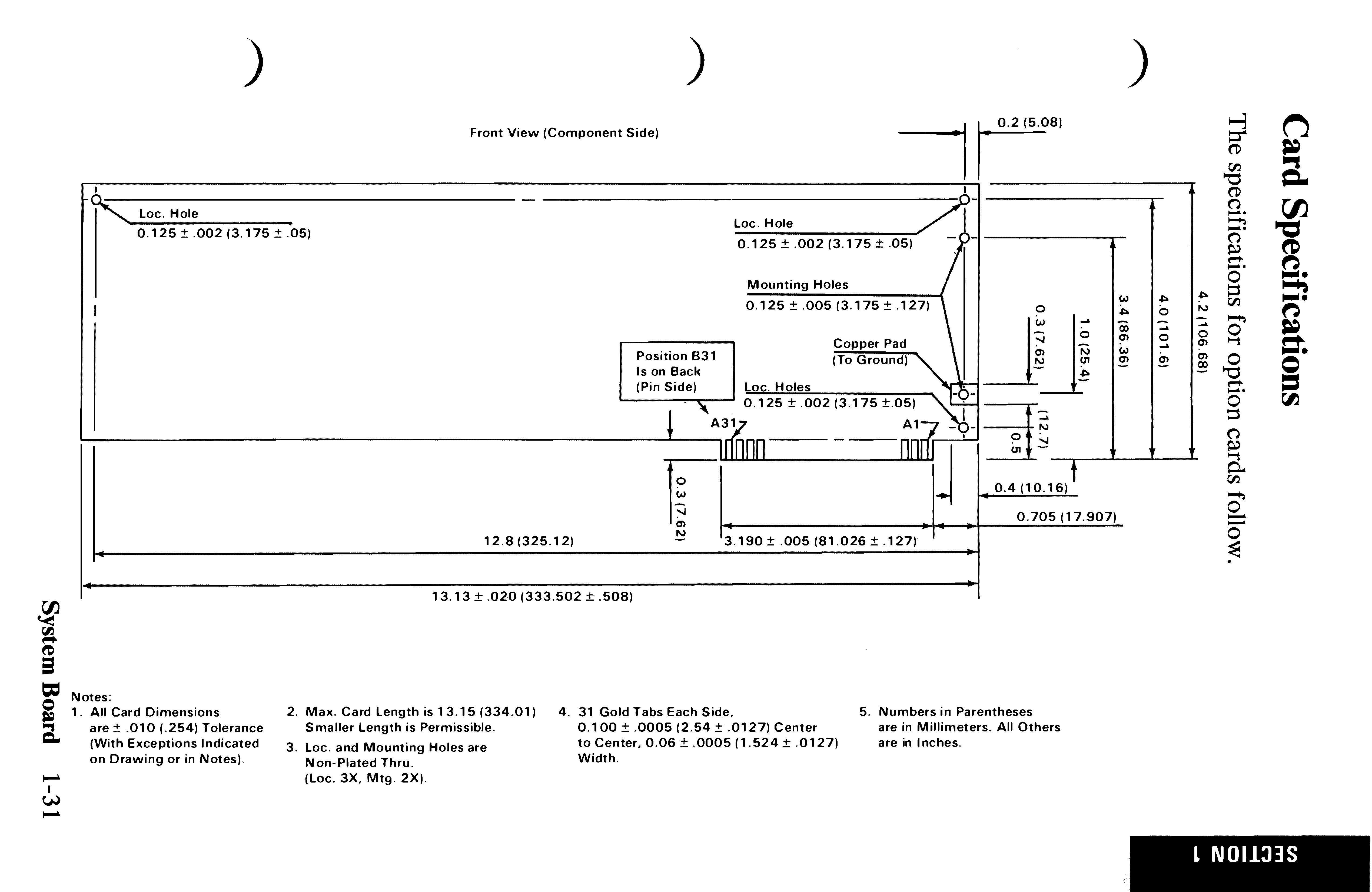
Technische Zeichnung einer Leiterkarte mit Bemaßungen
Front View (Component Side) Loc. Hole 0.125 ± .002 (3.175 ± .05) Loc. Hole 0.125 ± .002 (3.175 ± .05) Mounting Holes 0.125 ± .005 (3.175 ± .127) Copper Pad (To Ground) Position B31 Is on Back (Pin Side) Loc. Holes 0.125 ± .002

-
Thread
Empfehlung Kondensator für Hochpassfilter
/www.reichelt.de/vielschicht-smd-ab-g1812-c8029.html?ACTION=2&GROUPID=8029&START=0&OFFSET=30&nbc=1&SID=93236771b350246541fd553f319cc30e20cb290c59bc4e29b53f9 , naja, muß nicht sein, ist aber auch klein.
-
Thread
SMD-Schmelzsicherung als Leitungsschutz oder Alternative?
Für 5V gibt es jede Menge elektronische Sicherungen aka eFuse aka High Side Switch aka Leistungsverteilungsschalter. Die sind wahlweise selbstrückstellend und/oder mit Strombegrenzung und Übertemperaturschutz. Für 12V gibt's nicht ganz so viel Auswahl.
triggern (wobei sie ein Schmelzen von Leitungen schon verhindern), Sicherungen muss man wechseln, High-Side-Schalter oder Sicherung-IC kosten mehr Geld. Immer auch beachten, dass alle diese Dinge ganz schön Serienwiderstand mitbringen.
-
 Bild
Tabelle mit Adapter-Produktinformationen
Supply Adapter Adapts from standard 20-pin 0.1" socket to a standard 20-pin 0.1" header on the target side, provides a supply voltage of 5V. 98.-- Web Shop 8.06.16 6-Pin Needle Adapter Adapts from .1" 20-pin connector to .05" 6-pin needle pattern. Package includes: 6-pin cable with pins and legs 98.-- Web

-
Thread
Suche Fernschalter (Bausatz?) über Funk oder LWL ö.Ä
www.reichelt.de/halbleiter-relais-c7626.html?ACTION=2&GROUPID=7626&SEARCH=%2A&START=0&OFFSET=100&nbc=1&SID=9287a89daf4f151446ae48f4aab07db41bcb19c007d7d258c6846 Die enthalten oft einen Optokoppler zur galvanischen Trennung. Die Preise sind allerdings höher als normale elektromagnetische Relais oder Schütze
-
 Bild
Foto einer bestückten Leiterplatte
SIDE B BDM 010 100645011 EP GW<

-
Thread
Wilo Stratos PICO plus Pumpe Schnittstelle
dem Draht wird ein Parameter über eine 16-Bit-PID adressiert. Bisher decodierte PIDs (Service PV, sid 4): - `08fd` (u16) — Drehzahl in U/min - `08fe` (u32) — Förderstrom Q, /1000 → m3/h (die oberen Bits sind Flags) - `03a2` (u16) — Förderhöhe, /10000 → m - `09ee` (u8) — Leistung, *0,5 W - `09dc
-
Thread
Ansteuerung PFet Motorventil
Schaltplan im Kicad dann eben "schema" heißt. - https://dict.leo.org/französisch-deutsch/Schaltplan?side=right - https://dict.leo.org/französisch-deutsch/schema?side=left Im Deutschen ist ein Schaltplan aber eben keineswegs ein Schema. - https://de.wikipedia.org/wiki/Schaltplan - https://de.wikipedia.org
#7588008: > Eine Strommessung für beide Kanäle. Entgegen dem Vorschlag von Lothar > allerdings High-Side, da Bauteile besser verfügbar. An der Low Side bräuchtest du fast keine Bauteile ausser dem Shunt, wenn du mit dem Shunt (ziemlich) direkt auf den ADC fährst. Denn da kommt es sicher nicht aufs letzte
-
Thread
PWM Signal prüfen > Kontakt Schalten
kann ja nur 20mA schalten das reicht nicht ich bräuchte also noch einen Mosfet. Meine idee wäre High Side zu schalten. Wie baue ich denn die Messung mit den Comperatoren auf? Ich werde aus dem Datasheet leider gar nicht schlau.
um ein Relais direkt anzusteuern. > ich bräuchte also noch einen Mosfet. Meine idee wäre High Side zu schalten. Kann man natürlich auch machen. Berücksichtige dann die Stromaufnahme des TL431. Ein bisschen Strom fließt immer.