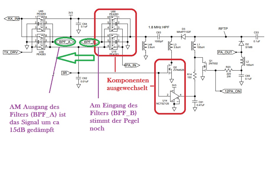
fact, that both rf signals from TX and RX of the network analyzer passes the same relay in the same time. Furthermore, the open contacts of the relays generate stubs in the signal path. To counter that facts it is nessecary to use four instead
drin, VSWR ist top! Blindanteile 0! Beim Senden Performance ohne Ende, heute aber so gut wie kaum RX! Dafür schon mehrfach in die eigene Elektronik eingestrahlt bis hin zum "killen" des CAT Interface. Dabei ist sie schon nach "pskreporter" ausgerichtet. Also in die Richtung der meisten aktiven Stationen
auf CB senden. > > QRP und schmalbandige Antenne. > Ich liege weiiiiiit weit über den nötigen 65dB. ;-) > > Selbst wenn mich jemand peilt, das saubere Signal ist ausschlaggebend > für Verfolgung. So lange in dem Bereich keine Störungen gemeldet werden, > die mir zuzuordnen sind, bin ich fein
Percy N. schrieb im Beitrag #7203290: > Rudi Ratlos schrieb: >> Percy N. schrieb: >> >>> BLÖDFUG! >> >> Dann rubbelst einfach mal mit wasserfreiem Tensid den Schmutz weg. > > Die Oberflächenspannung
SS PD5 A8 PB0 I B SPI SCK PD4 E T MOSI D PD3 A D 8 MISO D T PD2 A7/D7 PC7 S S KBYTES T O A6/D6 PC6 N E ROM O P A5/D5 PC5 D A D P A4/D4 PC4 T D H D SCI TxD PD1 A3/D3 PC3 R T A RxD PD0 P O A2/D2 PC2 P A1/D1 PC1 A0/D0 PC0 R/W STRB AS STRA PARALLEL I/O EQUIVALENT TO MC68HC24 Figure 1 MC68HC11A8 Block Diagram
Magic Numbers". Jedenfalls benötige ich letztlich Integer für die Funktionsparameter hBridge.gleisOn(n) bzw. hBridge.gleisOff(n). In allen Fällen habe ich noch den Cast denn man aktuell bei Cpp nicht mehr machen soll. Ich möchte das jetzt möglichst sauber haben wenn ich jetzt nochmal daran rumfummel
tlc relay control } [/c] Mainloop: [c] for(;;){ // gemessen: 355µs je Durchlauf rx_poll(); // UART receive command(); control(); update_all(); if( tick_10ms ){ tick_10ms = 0; SWtimer_tick(); // do delayed tasks } } [/c] Der
100MbpsFastEthernetPhysicalLayer TX/FXSingleChipTransceiver 4. Pin Configuration: DM9161 LQFP E S B 1 N E [ [ [ [ [ M D D D D D R Y Y Y Y I A C # H H H H M H / R ] P]P ] ] / / L D N N D [ [ [ [ O L S C N D E D D D D D D C C R D M R D R R R R MX X X 6 5 4 3 2 1 0 9 8 7 6 5 3 3 3 3 3 3 3 2 2 2 2 2 RXDV/TESTMODE
achieve an on-chip harmonic filter as well as a substrate-free assembly • providing a wide variety of RX FEM (LNA/SW) and full FEM (PA/LNA/SW) solutions to meet WiFi 802.11a,b,g,n,ac,ax,be requirements in medium power (+21dBm and lower) and high power (over +21dBm) applications WiFi 7 FEM - 6GHz Part No
von 100kHz bis 3GHz nur weiß ich nicht ob er einen DC Block hat? Teschnische Daten: Model NO: MANA-2N-X Power: 2W Frequenz: DC-3GHz Attenuation: 20dB Resistenz: 50ohm VSWR: <1.20 Dimension: 50*20mm Gewicht: 60g Steckverbinder: N male / N female Wäre es für den Anfang etwas nach dem Motto"
B e r n d W. schrieb im Beitrag #6018220: > So eine Gummi-Stummelantenne bringt recht wenig Signal auf UKW. Kann ich nicht bestätigen. Wenn ich an einen uralten Tek492 eine 2,4-GHz-Antenne dranklemme, dann
NC OUT 2 1 U e - N o V G 4 3 v n A a e 4 3 A R n r D t w 3 3 0 r V V V L > i , + + 7 - W x 3 0 m a C p p 3 1 a n C 3 n 4 n S b n v R 0 R 0 W n e r n ö S p g +8V r S o 8 6 a i S R 0 R 0 l t e +8V V t ä e 4,7µf C1 3 i s
disabled TX data input Transmit Not used el = 1 Internal TX data register enabled nFFS input (TX data register can be accessed) ef = 0 Receiver FIFO disabled RX data output RX data clock output Receive ef = 1 Receiver FIFO disabled nFFS input FFIT output (RX data FIFO can be accessed
verwenden. Bitte beachtet doch, dass die Fritzbox viel mehr Strom verbraucht, als z.B. die TP-Link WR841N. Vergleich 10 Watt vs. 1 Watt = 58 EUR vs. 5,80 EUR. Eine TP-Link WR841N kostet ca. 15 EUR -> somit hat man ein ROI innerhalb 4 Monate .... Also es bringt nichts, eine kastrierte Fritzbox laufen
Platz her möglich habe ich jeweils eine Spannungsklasse höher gewählt (z.B. 630V statt 400) und den 39nF mangels Verfügbarkeit durch 47nF ersetzt. Hoffentlich war die Zerstörung der Kondensatoren nicht eine beabsichtigte Schutzfunktion ;-) D.h. nach Tausch des ICs und der Kondensatoren funktioniert
Betriebstemperatur –30 °C bis +70 °C Emissionswert nach Be- 47 dB(A) triebsumgebung IP Schutzart Steuerung IP65 100 1,5 2 2,5 IP Schutzart Antrieb IP44 Länge (m) 1-flügelig und 2-flügelig Schutzklasse I Max. Schubgeschwindigkeit 16,5 mm/s Tabelle Füllung Max. Zug- und Druckkraft je Flügel 2.000 N Höhe (m) Füllung
disabled TX data input Transmit Not used el = 1 Internal TX data register enabled nFFS input (TX data register can be accessed) ef = 0 Receiver FIFO disabled RX data output RX data clock Receive output ef = 1 Receiver FIFO disabled nFFS input FFIT output (RX data FIFO can be accessed
value Register 4-2. • The RxA, RxB, and RxW bits return to controlling When the RxHW bit is a “0”, the selected resistor net- the terminal connection state of that resistor net- work is forced into the following state: work • The
value Register 4-2. • The RxA, RxB, and RxW bits return to controlling When the RxHW bit is a “0”, the selected resistor net- the terminal connection state of that resistor net- work is forced into the following state: work • The
value Register 4-2. • The RxA, RxB, and RxW bits return to controlling When the RxHW bit is a “0”, the selected resistor net- the terminal connection state of that resistor net- work is forced into the following state: work • The
value Register 4-2. • The RxA, RxB, and RxW bits return to controlling When the RxHW bit is a “0”, the selected resistor net- the terminal connection state of that resistor net- work is forced into the following state: work • The
7 8 2 ATT8dB 82 IO IO 219 nRESET 30 MDIO GND_IO 96 N V GND K RN7 D8 V G . 1 K 1 ATT10dB IO VCCINT . RX_DV VDD_IO 3 RN9 GND GND GND 1 0 4 5 D7 2 1 81 220 + 29 97 + N x 9 ATT20dB IO IO +3.3V VDD_IO nLED1 R 4 3 3 6 2 1 D6 D 80 221 D D 28 98 4 5 1 R N GND GND N N GND_IO nLED2 4 3 2 1 2 7 D3 2 1 G 79 222 G G 27 E 99 3 6 IO IO RX_CLK R R nLED3 DUPLEX/ 1 8 2 1 V 78 223 26 E E L L O O 100 2 7 4x220E . VCCIO3 IO R N I I R T R P 1 2 P C C NETACTIVE/ 3 77
’s UART RX FIFO has not reached the FLOW OFF watermark level of 448 bytes and is ready to accept more data. When the amount of data in the RX FIFO reaches the watermark, the CP2102N pulls RTS high to indicate to
’s UART RX FIFO has not reached the FLOW OFF watermark level of 448 bytes and is ready to accept more data. When the amount of data in the RX FIFO reaches the watermark, the CP2102N pulls RTS high to indicate to
’s UART RX FIFO has not reached the FLOW OFF watermark level of 448 bytes and is ready to accept more data. When the amount of data in the RX FIFO reaches the watermark, the CP2102N pulls RTS high to indicate to
’s UART RX FIFO has not reached the FLOW OFF watermark level of 448 bytes and is ready to accept more data. When the amount of data in the RX FIFO reaches the watermark, the CP2102N pulls RTS high to indicate to
’s UART RX FIFO has not reached the FLOW OFF watermark level of 448 bytes and is ready to accept more data. When the amount of data in the RX FIFO reaches the watermark, the CP2102N pulls RTS high to indicate to
90% der > Nennkapazität. > Gut, dann werde ich VBUS einen 4.7u verpassen. Also für die 100n und 1u hätte ich noch 1u/25V und 100n/50V X7R da, sollte also kein problem sein.... Bei der HV habe ich mal die Bauteile der Theremino übernommen, alle mit Farnell-Bestellnummern, sieht eigentlich
2 D1 0 B1, Bit 1 B2, Bit 1 B3, Bit 1 B4, Bit 1 D0 0 B1, Bit 0 B2, Bit 0 B3, Bit 0 B4, Bit 0 Pixel n Pixel n+1 Pixel n+2 Pixel n+3 16 bits 16 bits Look-up table for 65k color data mapping (16 bits to 18 bits) 18 bits Frame memory R1 G1 B1 R2 G2 B2 R3 G3 B3 Note 1: The data order is as follows, MSB=D15
SYSTEMS - GSM HANDSETS AND ACCESSORIES - OTHER TELEPHONE SET FEATURES SOT23-5L (SC-59) SOT23-6L (SC-59) n 4 UNIDIRECTIONAL TRANSIL FUNCTIONS ESDAxxSC5 ESDAxxSC6 n LOW LEAKAGE CURRENT: I mRx. < 20 A at VBR n 500 W PEAK PULSE POWER (8/20 s) FUNCTIONAL DIAGRAM SOT23-5L DESCRIPTION The ESDAxxSC5 and ESDAxxSC6
Description Pin Description TX1 +/- High speed data path (TX for GND Cable Ground TX2 +/- USB, or RX for DP Alt Mode) RX1 +/- High speed data path (TX for VBUS Cable bus power RX2 +/- USB, or RX for DP Alt Mode) SBU1 For sideband use (Not used for D+/D- USB 2.0 Interface SBU2 USB) Plug configuration
N _O O N FORCE_PLL_ON LL K N _ see notes From / To P AC _ E TRX_OFF _A L R From / To N R P _ TRX_OFF _ F T N C F _ F A X_ E OF X R AR X R T X_ T T SLPTR = 1 SHR or Detected TX_START BUSY_RX_AACK RX_AACK_ON
wired AND ausgefüht, bei reinem Empfangsbetrieb seitens der Slaves hängen also alle Slaves mit ihrer RX-Leitung über eine Schutzbeschaltung an der gepufferten TX-Leitung des Mastercontrollers, bei beidseitigem Senden und Empfangen senden die Slaves auf Anfordreung vom Master auf ein und dieselbe Rückleitung
Controller war mir schon klar, aber bei 150 LED's sind das auch schon 10-18 Stk. Ich meine klar so'n Tiny2313 z.B. kostet wirklich nicht mehr die Welt... 10 Stk. wären immer noch günstiger als ein MAX5962 wenn man Ihn kaufen müsste. Ich denk mir mal ne Schaltung aus ;-) Auf jeden Fall bekommen sie
differences require it. Philips Semiconductors Opto-isolation - full 100kHz clock speed 1 G *Note: 6N137 data suggests 0.1uF mounted between pins 5 and 8 P OptoIsolation at full 100kHz clock speed. Here the single bus line to the left of the circuit is split by the 82B96 into two separate signals RxD
differences require it. Philips Semiconductors Opto-isolation - full 100kHz clock speed 1 G *Note: 6N137 data suggests 0.1uF mounted between pins 5 and 8 P OptoIsolation at full 100kHz clock speed. Here the single bus line to the left of the circuit is split by the 82B96 into two separate signals RxD
Schließe an dem FTDI die TX und RX Pins zusammen und versuch doch mal, ein Zeichen durch das Programm zu verschicken. Dies nennt man auch "echo" Und sag uns bitte ein bisschen mehr...deine Infos sind viel zu wenig um das Probelm konkret
00000050 69 73 20 70 72 6f 67 72 61 6d 20 63 61 6e 6e 6f |is program canno| 00000060 74 20 62 65 20 72 75 6e 20 69 6e 20 44 4f 53 20 |t be run in DOS | 00000070 6d 6f 64 65 2e 0d 0d 0a 24 00 00 00 00 00 00 00 |mode....$.......| 00000080 91 14 4a 02 d5 75 24 51 d5 75 24 51 d5 75 24 51 |
Mir gehts aber nicht ums Geld, sondern umn den Aufwand bei neuen Systemen. Jetzt hab ich Cool'n'Quiet auch abgeschalten, und noch'n paar, jetzt sieht die *Meß-Sache* (System-Info-Profiler) ganz anders aus: muß ich aber noch länger verifizieren. Wovon dieses plötzliche 'Ungleichgewicht' (Bilder
\n><\r><\n> outbuf5: 50000010<\r><\n><\r><\n> outbuf5: 10000010<\r><\n><\r><\n> outbuf5: 30000010<\r><\n><\r><\n> Calibration run 1<\n><\r> Channel 1: ADC average value = 126 Diff = -2<\r><\n>
r> Channel 1: ADC average value = 126 Diff = -2<\r><\n> Channel 2: ADC average value = 65 Diff = -63<\r><\n> Channel 3: ADC average value = 0 Diff = -128<\r><\n> Channel 4: ADC average value = 0 Diff = -128<\r><\n> Calibration run 5<\n><\
2 2 A DC7 P_DVCC P_DVCC 14 P1.2/TA1 P3.7/URXD1 35 U R 1RX UART1RX DAC0 DAC1/ SVSi nR15 TI_MSP43 0F16 1 GIO2 3 4 GIO3 RADIO_ GIO0 15 34 UART1TX Ti mer A Capt ur e 4 DMAE0 SVSout MOUNTING HOLES P1 3 /T 2 X 0 P3. /UX D UserINT 5 6 RESET 16 L A 33 U RT0RX 5 6 RADIO

 Bild
Bild
 Bild
Bild
 Bild
Bild