-
Thread
China-Netzteil A15W bei AliExpress
preiswertes Linear-Netzteil. Das Gerät ist jedenfalls wesentlich günstiger, als die abenteuerlich teuren "HighEnd"-Netzteile aus der HiFi-Szene...
Michael B. schrieb im Beitrag #7873594: > Es handelt sich um ein Linear geregeltes Netzteil mit dem LowDrop-Regler > LT1085. Low Dropout. Allerdings ist das bei der Beschaltung nicht relevant. Du hast 21V am Eingang gemessen bei 12V Ausgang. Das ist weit von der 1V Dropout-Differenzspannung entfernt
-
 Bild
Bild
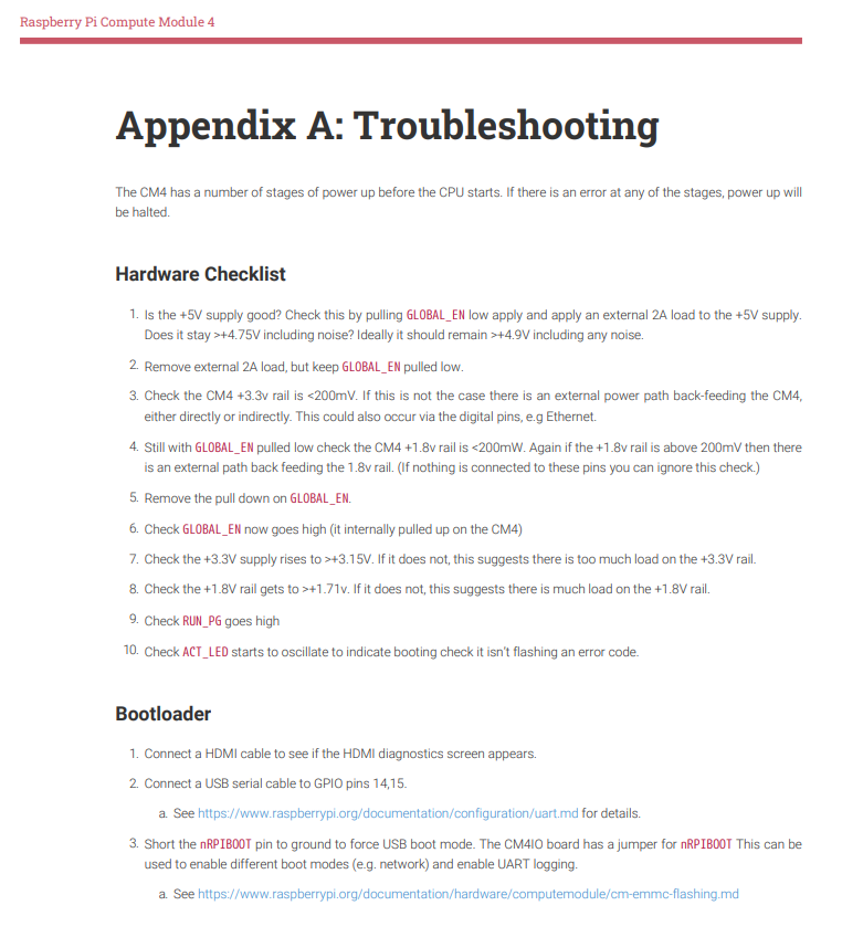
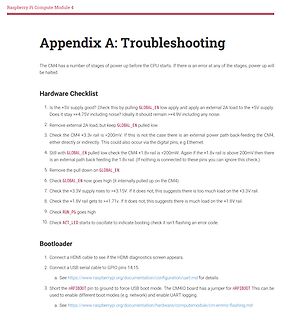
Troubleshooting Guide Raspberry Pi Compute Module 4
power up will be halted. Hardware Checklist 1. Is the +5V supply good? Check this by pulling GLOBAL_EN low and apply an external 2A load to the +5V supply. Ideally it should remain >+4.75V including noise. Does it stay >+4.9V including any noise. 2. Remove external 2A load, but keep GLOBAL_EN pulled low.
-
 Bild
Bild
Ausschnitt aus einem Datenblatt der AP3031
4 CTRL Enable and Dimming Control Pin. Connect to a high input to enable the IC or a low input to disable the IC. • If logic low time is more than about 0.7ms and then the IC is enabled, the AP3031 will soft start to protect system departments. • If logic low time is less than about 0.7ms and then the IC is enabled, the AP3031 will hold on standby mode and start directly to achieve high frequency dimming.

-
Thread
Verständnisfrage Datenblatt AP3031 PMIC
Meine Glaskugel meint folgendes: Es gibt vier Möglichkeiten des Dimmens: 1. Low frequency dimming mit Softstart (evtl. hörbar) "will start smoothly to protect the supplier." "soft start to protect system departments." 2. High frequency dimming ohne Softstart (erhöhte
RC-Filter siehe Dimming Control Using Filtered PWM Voltage Ich erkläre mir das so: Wenn die Low-Zeit kürzer als 700µs ist, startet die Stromerzeugung aus dem Standby heraus sofort und versucht mit allen Mitteln, den Sollstrom schnell zu erreichen. Wenn die Low-Zeit länger als 700µs ist, wechselt
-
Thread
Hilfe benötigt! Pi Compute Module 4 Carrier Board ohne Funktion!
nichts anderes tut, als einen unbenutzten Port-Pin periodisch im 5-Sekunden-Takt abwechselnd auf High und Low zu setzen, und misst an dem Pin. Wenn schon das nicht funktioniert, braucht man sich nicht mit Gerber-Dateien und Stücklisten zu befassen.
anderes tut, > als einen unbenutzten Port-Pin periodisch im 5-Sekunden-Takt abwechselnd > auf High und Low zu setzen, und misst an dem Pin. Und das tut und testet er auf einem Board, das nachweislich funktioniert. Harald K. schrieb im Beitrag #7873208: > Es gibt einen Schaltplan des "Compute
-
Thread
UART Idle-Pegel (bei ATMegas): Steckt dahinter ein Pull-Up?
Wird der Idle-Pegel eines ATMega-UART (High) durch einen internen Pull-Up erzeugt, so dass versehentliches externes Anlegen von Low im Idle verkraftet wird, oder ist TXD ein Push/Pull-Pin?
bit in the USARTn.CTRLB register), which prevents the transmitter from driving a pin to a logical high level, thereby constraining it to only be able to pull it low."
-
Thread
Port Verhalten ESP8266 im DeepSleep
den Deep Sleep schickt. Gehen die in einen unbestimmten Zustand, verbleiben in ihrem Status oder High Z? Hintergrund: Ich schalte einen P Kanal Mosfet, also ziehe ich den Port auf low, im Deep Sleep soll aber der Mosfet ausgeschaltet also nicht leitend bleiben (über Pullup Widerstand). Vielen
mal untersucht: https://www.arduinoforum.de/arduino-Thread-ESP8266-GPIO-w%C3%A4hrend-deep-sleep-auf-high-halten?pid=106331#pid106331
-
Thread
Frage zu GPS LNA
rev=47e87c42cf9a46ae8b42873b3816e115 Verständnisfrage 1: Was macht der VEN-Pin genau? Wenn der high ist, arbeitet der LNA und verstärkt, klar. Wenn der auf low ist: - sperrt der, d.h. am Ausgang kommt nichts raus? - verstärkt der nicht, d.h. am Ausgang kommt das unverstärkte Eingangssignal raus?
Frank K. schrieb im Beitrag #7872549: > Verständnisfrage 1: > Was macht der VEN-Pin genau? Wenn der high ist, arbeitet der LNA und > verstärkt, klar. Wenn der auf low ist: > - sperrt der, d.h. am Ausgang kommt nichts raus? > - verstärkt der nicht, d.h. am Ausgang kommt das unverstärkte > Eingangssignal
-
Thread
Entladekreis für 6S Lipos, geht das so?
Aber warum sollte der MOSFET in den Triodenbereich kommen? Ich dachte, > dass der Komp entweder High oder Low schaltet. Er schaltet ohne Hysterese direkt an der Schaltschwelle wild hin- und her, und die Gatekapazität macht zusammen mit dem daraus Pullup daraus eine wellige Gleichspannung. Michael
verbaut. Hatte ich da. Robert schrieb im Beitrag #7872143: > Ich dachte, > dass der Komp entweder High oder Low schaltet. Nein. Komparatoren sind auch nur (schlechte) OpAmps. (ok, es gibt einige Exemplare mit geringster interner Hysterese, der LN393 ist keiner davon, würde hier nicht helfen).
-
Thread
Hugging Face-Roboter, Ubuntu für DragonWing, neue Methode zur Behebung von Fehlern in PCBs
den Tisch. Sei dem wie es sei, kündigen die Uptoniten nun unter https://www.raspberrypi.com/news/lower-prices-for-4gb-and-8gb-compute-module-4/ eine Preissenkung an: [c] From now, if you buy a standard operating temperature Compute Module 4 from a Raspberry Pi Approved Reseller, it will cost you $5
Abbildung gezeigt. 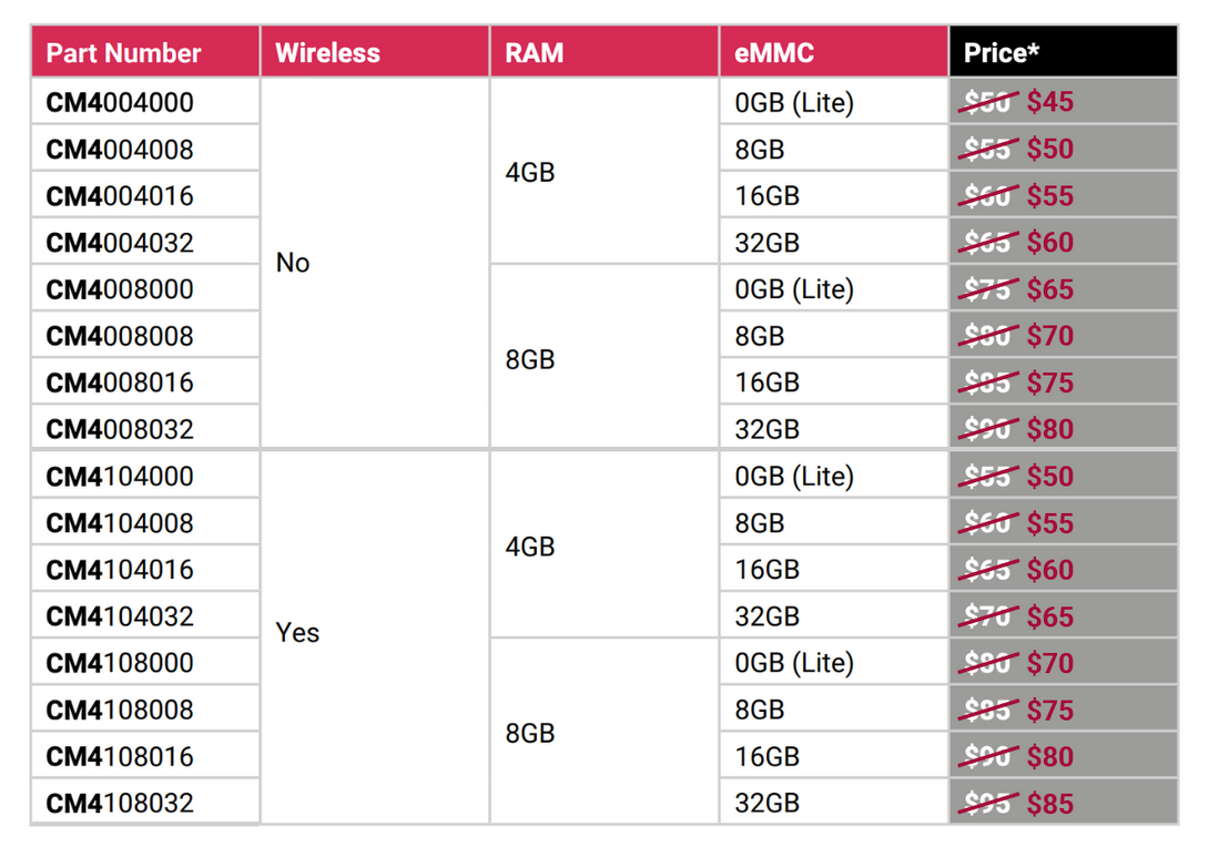 Bildquelle: https://www.raspberrypi.com/news/lower-prices-for-4gb-and-8gb-compute-module-4/ Über die Ursachen dieser Preisfindung vermelden die Uptoniten wie erwartet nichts - denkbar wäre es, dass entweder zu viel Stock auf Halde liegt, oder aber
-
 Bild
Bild
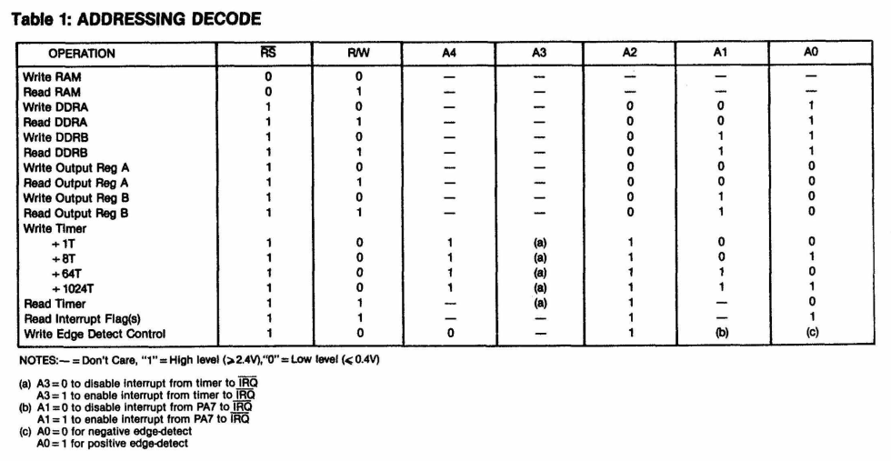
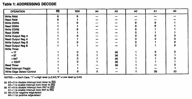
Tabelle zur Adressdekodierung eines Mikrocontrollers
Interrupt Flag(s) 1 1 — 1 1 — 1 Write Edge Detect Control 1 0 0 1 (b) (c) NOTES: — = Don't Care, "1" = High level (>2.4V), "0" = Low level (<0.4V) (a) A3=0 to disable interrupt from timer to IRQ A3=1 to enable interrupt from timer to IRQ (b) A1=0 to disable interrupt from PA7 to IRQ A1=1 to enable interrupt
-
 Bild
Bild
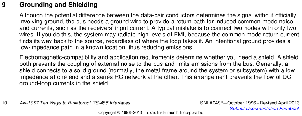
Textauszug aus einem Texas Instruments Application Note
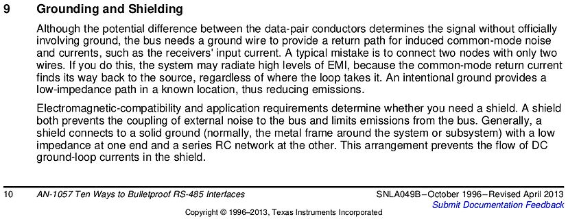
typical mistake is to connect two nodes with only two wires. If you do this, the system may radiate high levels of EMI, because the common-mode return current finds its way back to the source, regardless of where the loop takes it. An intentional ground provides a low-impedance path in a known location
-
 Bild
Bild
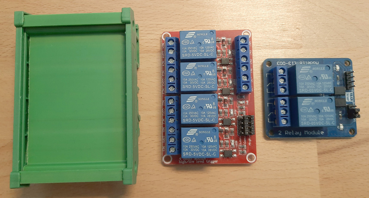
Relais-Module und Gehäuse
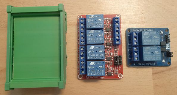
SONGLE 10A 250VAC 10A 125VAC 10A 30VDC 10A 28VDC SRD-5VDC-SL-C NO NC 2 IN 3 IN high/low level trigger 2 Relay Module
-
Thread
Neue Bauteile: ESP32-C5 in Produktion, spulenloses Relais und neue Mikrocontroller
Silicon Labs Unterstützung für die folgenden Funkstandards: [c] Protocol Support Bluetooth Low Energy (Bluetooth 5.4) Direction finding using Angle-of-Arrival (AoA) and Angle-of-Departure (AoD) Bluetooth mesh Channel Sounding [/c] Für das System spricht unter anderem, dass
nehmen, ist per se nicht neu. MicroChip integriert beispielsweise immer mehr Funktionen in seine High End-Programmiergeräte (siehe auch https://www.youtube.com/watch?v=yrM78fs-AR8) . Mit dem in der Abbildung gezeigten und aufgrund der Beschriftung der Platine wohl von Elprotronic stammenden Programmiergerät
-
Thread
Reset mehrerer ISERDESE3
/TX-Bitslices verwendet. XAPP1274 ab Seite 44: https://docs.amd.com/v/u/en-US/xapp1274-native-high-speed-io-interfaces
durch 8-fache Überabtastung. Ziemlich cool. https://docs.altera.com/r/docs/683792/25.3.1/stratix-10-high-speed-lvds-i/o-user-guide/dpa-block Extrapunkte gibt es für die Anmeldung im Forum. Herzlich Willkommen.
-
Thread
Benötige Hilfe bei meinem Schaltplan
. Version > weggelassen. Das ist auch OK. Im Datenblatt steht dazu: "Enable Pin. Drive EN pin low to turn on the device, drive it high to turn it off. Floating is default low."
-
 Bild
Bild
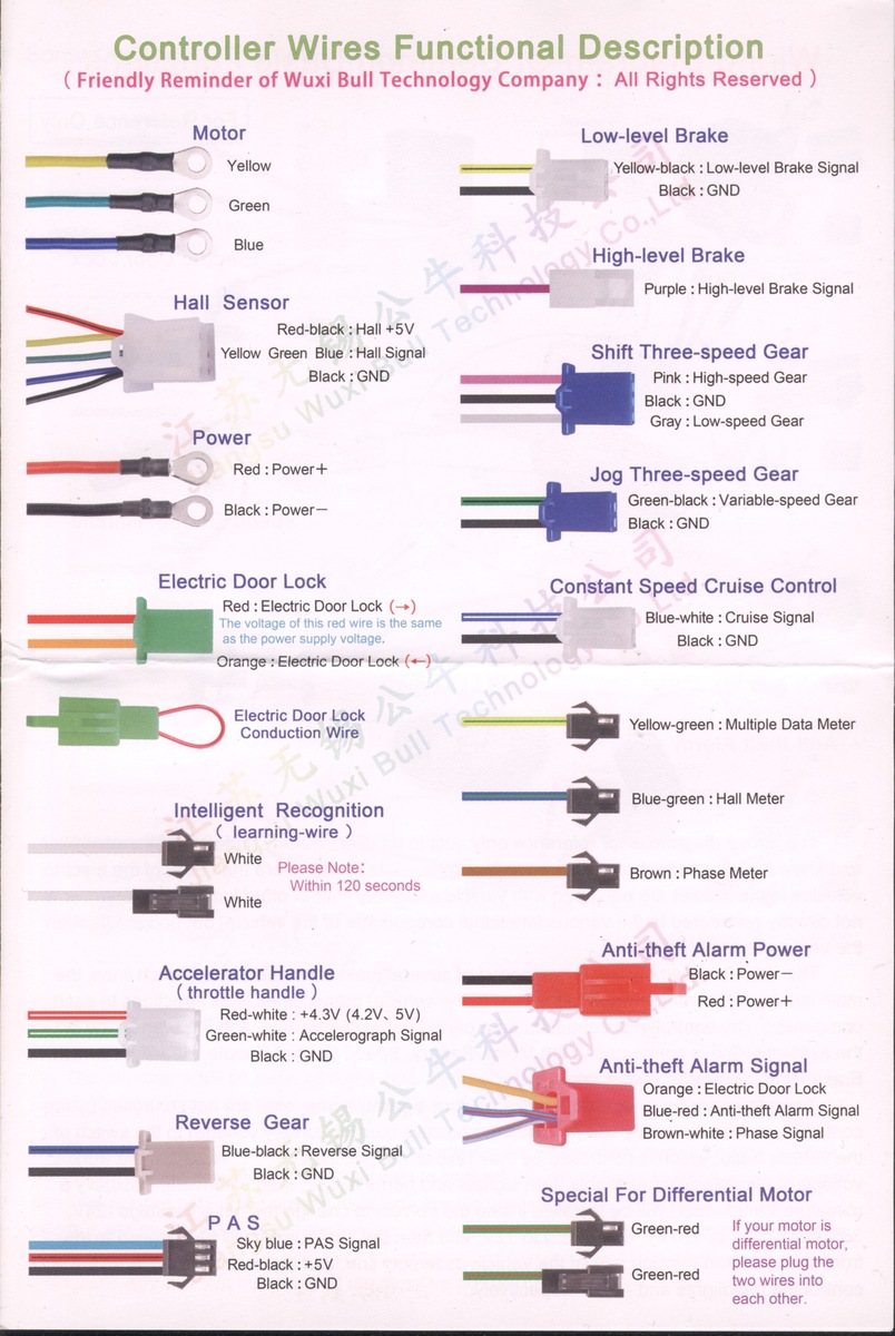
Belegungsplan der Controller-Kabel für E-Bike Komponenten
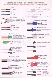
Controller Wires Functional Description Motor: Yellow, Green, Blue Low-level Brake: Yellow-black, Black High-level Brake: Purple Hall Sensor: Red-black, Yellow, Green, Blue, Black Shift Three-speed Gear: Pink, Gray, Black Power: Red, Black Jog Three-speed Gear: Green-black
-
Thread
Was verändert sich bei falscher Impedanz einer Elektretmikrofonkapsel
richtigen Maßen bestellt, die laut den Angaben da um die -45dB Empfindlichkeit haben sollen und zwischen "LowImpedance" und "2 kihloom" (Beim Chinesen im Shop so beschrieben) haben. Das sind dann 5 verschiedene Modelle und ich hoffe, Eines davon wird wohl halbwegs funktionieren.
https://de.wikipedia.org/wiki/High_Fidelity Naja schon ziemlich alt. Das werden die meisten Geräte leicht übertreffen. Jürgen schreibt jedenfalls von irgendwelchen Elektretmikrofonkapseln, die er irgendwo gefunden oder ausgebaut
-
Thread
MS51FB9AE Programmieren
ich bei 3,3 V → 3,3 V überhaupt Level-Shifter einplanen? – Tipps für saubere Reset-Sequenz (nRESET low/high)? *Alternativen* – Lohnt sich die Mühe oder ist ein günstiger ISP-Programmer die bessere Wahl?
-
Thread
Digitalkamera auf Basis von ESP32-P4, neue ST-Audiosoftware uvam
guidance, decreased 830 basis points year-over-year, mainly due to product mix and, to a lesser extent, higher unused capacity charges and lower sales price. [/c] Geradezu „beeindruckend“ ist in diesem Zusammenhang der Zusammenbruch des Gewinns, der - mit rund 3 Millionen US-Dollar - nun im Bereich eines
MIL-qualified JANSR die, providing a cost-effective power device for New Space and Low Earth Orbit (LEO) applications. The ceramic package is hermetically sealed and developed for total dose and Single-Event-Environments (SEE). The devices are designed to meet the MIL-PRF19500/746 standard
-
Thread
STM32H743 & LTC1403 SPI Timing
im Timing-Diagramm sind doch üblicherweise min-Zeiten. Ich lese das Timing-Diagramm so: CONV high, t4 warten, CONV low. Jetzt die SPI starten und 16 Bit einlesen. Die ersten beiden Bits werden dann verworfen da der Sender noch Hi-z ist. Die restlichen 14 werden ausgewertet.
sein wie es dir passt." Ebenso steht da >> It is also good practice to keep the width of the low portion of the >> CONV signal greater than 15ns to avoid ... Also nicht zu lange High bleiben, so das Low mindestens 15 ns ist. Oder mit den dort aufgeführten Problemen leben. Insgesamt interpretiere
-
Thread
Motor mit Elektronik verstehen
BRK-Eingang. > https://foneacc.com/FABL4275-p00277p1.html BRK: offen lassen sollte reichen, open=high und high=motor on (=brake off) PWM: open=high und high=motor off. Mit Widerstand unter 0,5V ziehen=low, low=motor on (aber das hat der TO schon probiert) Wie sind die unbelasteten Spannungen an
-
 Bild
Bild
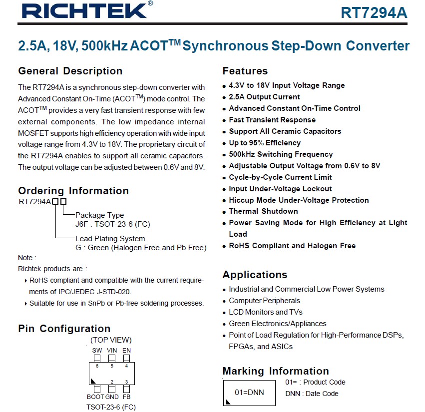
Datenblatt des RT7294A Synchronous Step-Down Converters
Under-Voltage Lockout Hiccup Mode Under-Voltage Protection Thermal Shutdown Power Saving Mode for High Efficiency at Light Load RoHS Compliant and Halogen Free Ordering Information RT7294A Package Type J6F: TSOT-23-6 (FC) Lead Plating System: G: Green (Halogen Free and Pb Free) Applications Industrial and Commercial Low Power Systems Computer Peripherals LCD Monitors and TVs Green Electronics/Appliances Point of Load Regulation for High-Performance DSPs, FPGAs, and ASICs Pin Configuration (TOP VIEW) SW, VIN, EN, 6,

-
 Bild
Bild
Handgezeichnetes Blockschaltbild mit Pinbelegungen
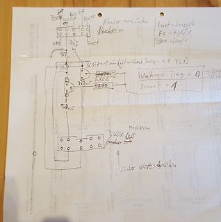
RXD EA PSEN TXD OUT Vects /schleife nach innen Reset = Low/0 EA = High/1 PSEN = Low/0 BC337 = ein (während Prog = 0) P3,7 RXD RXOUT RX2 RXOUT TXOUT nach oben Blockschaltbild Loch Sitzes brauchen
-
Thread
Transistor Schaltet anders
Bei dem Controller ist das Register nach Resett für P3 auf #%11111111 also alle Pins von Port 3 auf HIGH. Der BC327/40 schaltet mit LOW also 0 ein. Das bedeutet das nach dem Resett, welcher durch das Programmiergerät ausgelöst wird, der Transistor aus ist. Dann wenn mein Programm nach dem Flash gestartet wird, schreibe ich den Pin auf 0 um, so das an P3.7 LOW anliegt und die beiden Transistoren für TxD und RxD schalten können. Diese kleine Schaltung funktionier einwandfrei. Auf dem Steckbord habe ich das mit LEDs getestet. Aber in der Verbindung mit
-
 Bild
Bild
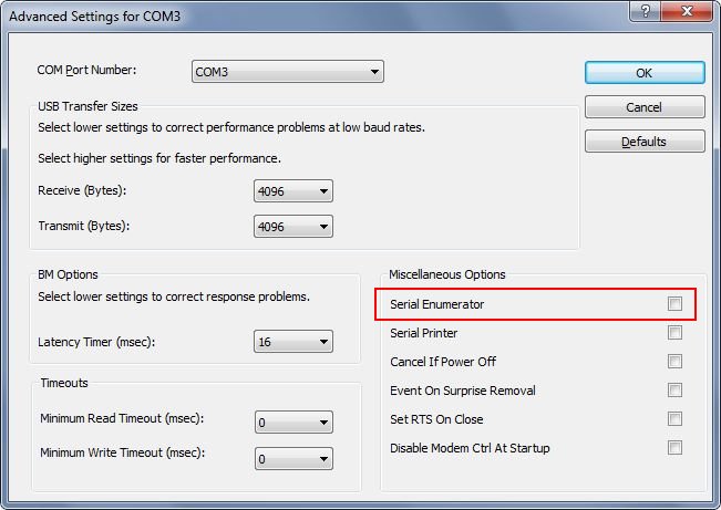
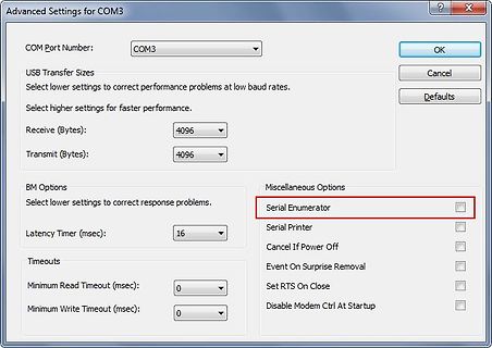
Einstellungen für COM3 Port
Advanced Settings for COM3 COM Port Number: COM3 OK Cancel Defaults USB Transfer Sizes Select lower settings to correct performance problems at low baud rates. Select higher settings for faster performance. Receive (Bytes): 4096 Transmit (Bytes): 4096 BM Options Select lower settings to correct response
-
Thread
MicroPython 1.25, preiswerter Renesas-Microcontroller mit mehr Pins uvam
der offiziellen Beschreibung liest sich dies folgendermaßen: [c] PIC16F17576 MCUs feature a new low-power comparator and voltage reference combination that can operate while the MCU core is in sleep mode, allowing for continuous analog measurement while consuming less than 3.0 µA of current. The Analog
In addition, an integrated High-speed On-Chip Oscillator (HOCO) enables the fastest wake-up time for this class of microcontroller. The fast wake-up enables the RA0 MCUs to stay in Software Standby mode more of the time, where power
-
Thread
Funkmodul gesucht
index.html Bei den primitivsten Funkmodulen musst du das Nutzsignal vor dem Senden passend codieren. High und Low Pegel haben bestimmte minimale und maximale Zeiten und mit Mittel muss das Signal neutral (gleich viel High wie Low) sein. Oft muss eine Präambel benutzen, damit sich der Empfänger darauf Einschwingen
-
Thread
RC-Signale einlesen - so einigermassen bulletproof?
bitte nur um Hilfe bzw. kurzes Mitdenken bei der Logik. Die Signale kommen etwa alle 20ms, sind idle low und dann jeweils für 1-2ms high. Um diese Zeit geht es. Hier sind das erstmal nur zwei Signale, könnten aber auch mehr sein, die kommen jeweils auf eigenen Eingängen an. Das Problem ist nun, daß die
: > RC = (Infrared) Remote Control? Wohl kaum. Die Abgaben "alle 20ms" und "jeweils für 1-2ms high" lassen eher vermuten, dass es sich um ein Servosteuersignal für Modellbauservos handelt. Cyblord -. schrieb im Beitrag #7865420: > 0,5µS Ja, ja. Eine Angabe von 0,5 Mikrosiemens hätte eher etwas
-
Thread
PWM Lüfter Steuerung mit ESP8266 Tacho Problem
Wenn du die Lüfter low-side schaltest, dann funktioniert der Tachoausgang nicht mehr.
BC547 (o.ä.) braucht auch keinen Pulldown an der Basis, da er den Pin durch den Basisstrom selber low zieht.
-
 Bild
Bild
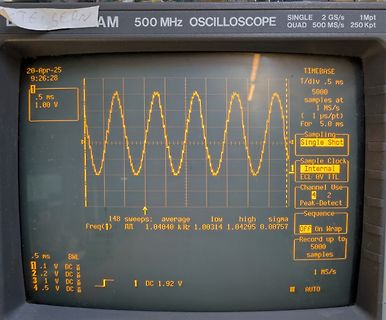
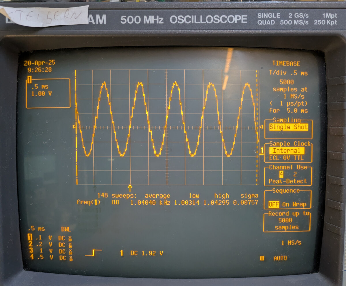
Abfotografiertes Oszilloskop mit Sinuswelle
0V TTL Channel Use 4 Peak-Detect Sequence Off On Wrap Record up to 5000 samples 148 sweeps: average low high sigma Freq(1) 1.04040 kHz 1.00314 1.04295 0.00757 1 DC 1.92 V 1 MS/s .5 ms .1 V DC 2 .2 V DC 4 .5 V DC