-
Datei
tn13rfm.asm
reti;rjmp ADCC ;ADC Conversion Complete RESET: dec rx_lastid ;rx_lastid auf 255 setzen ldi page_cnt, 32 ;Auf 32 laden für normalen Programmablauf ; ldi page_cnt, 0 ;Auf 1 laden für Programmiermodus von Page 0 rcall init REVERT: loop: cbi RF_PORT, CS ;CS auf 0(aktiv) nop ;A bisserl Zeit lassen nop rf12_
in „Funkmodul RFM12 in Assembler“ · Mikrocontroller und Digitale Elektronik ·
-
Datei
ClipDec.c
Antoniak @ 2004, Poland #include <io2313.h> #include "LCD_44780.h" #include <progmem.h> #include <sig-avr.h> //========================================== PORT ALIASES ================================= #define IN (unsigned char)(PIND&0x04) #define CALL_PIN (unsigned char)(PIND&0x08) //===================
in „Kryptischer CLIP-Decoder“ · Mikrocontroller und Digitale Elektronik ·
-
PDF
Futaba_M202MD01BA_v1.0.pdf
bit 4 8 Gnd Ground 9 DB3 data bit 3 10 Gnd Ground 11 DB2 data bit 2 12 Gnd Ground 13 DB1 data bit 1 14 Gnd Ground 15 DB0 data bit 0 16 Gnd Ground 17 /WR Write signal 18 Gnd Ground 19 n.c. not connected 20 Gnd Ground 21 n.c. not connected 22 Gnd Ground 23 /SEL Select signal 24 Gnd Ground 25 /TEST Test
-
PDF
DenisK_SCH.pdf
1 2 3 4 5 +3.3V AVR ISP 6pol R5,R6,R7 nicht best▯ückt. R6 R5 47K 47K R3 470 R7 U1 C10 A ISP_MISO ISP 47K ATMEGA128A-AU A 210-72-03GB01 10nF R2 1 2 R4 1 PEN# AVCC 64 +3.3V 470 ISP_SC3 1 2 4 470 ISP_MOSI 2 PE0(RXD0/PDI)
in „ATMEGA128A-AU vs 128A U-TH und 3V vs 5V ISP Programmierspannung“ · Mikrocontroller und Digitale Elektronik ·
-
Datei
iom88.h
example showing the SFR_B() macro call, * the expanded result and usage of this result: * * SFR_B(AVR, 0x1F) Expands to: * __io union { * unsigned char AVR; // The sfrb as 1 byte * struct { // The sfrb as 8 bits * unsigned char AVR_Bit0:1, * AVR_Bit1:1, * AVR_Bit2:1, * AVR_Bit3:1, * AVR_Bit4:1, * AVR_Bit5:1, * AVR_Bit6:1, * AVR_Bit7:1; * }; * } @ 0x1F; * Examples of how to use the expanded result: * AVR |= (1<<5); * or like this: * AVR_Bit5 = 1; ****************************************************************
in „IAR Embedded Workbench for Atmel AVR“ · Mikrocontroller und Digitale Elektronik ·
-
Datei
123.c
#include <avr/io.h> #include <avr/interrupt.h> #include <util/delay.h> #include <stdint.h> #include <inttypes.h> #include <avr/pgmspace.h> #ifndef F_CPU #define F_CPU 4000000L #endif #define XTAL F_CPU #define DEBOUNCE
in „LED Fading und Uhr beides benötigt Timer1“ · Mikrocontroller und Digitale Elektronik ·
-
Datei
stk500_at90s1200_mega8535.asm
Fredriksen, Morten W. Lund ;* Haakon Skar, Paal Kastnes ;* ;* DESCRIPTION ;* This is a serious hack of AVR910, designed to work on the STK500. The ;* STK500 uses basically AVR910, with code that only enables it when the ;* 'program' button is held down. BUT if you fix your STK500 you need to ;* use a Mega8535
in „STK500 defekter Prozessor“ · Mikrocontroller und Digitale Elektronik ·
-
Datei
Version3_mit_stellen_po--sLeuchten_ohne_DCF.asm
; --------------------------------------- ; (c) 2004-05 Th.Klapper ; Version 3.0 ; Hardware Atmel AVR AT90S2313-PDIP @ 4MHz ; ; Versions Features: ; Zeiterzeugung mit externem 4MHz Quarz und Interrupt ; Stellen nur über Taster ; keine DCF Auswertung ; keine Status LEDS ; ----------------------------
-
Datei
hd44780.h
Header fuer grundlegende Funktionen eines HD44780 kompatiblen LC-Textdisplays Hardware : Text-LCD MCU : AVR 14.02.2020 R. Seelig Hinweis: Alle Anschlusspins des LCD muessen mit einem 1k Pop-Up Widerstand gegen +5V geschaltet sein, weil ein Hi-Pegel auf den Leitungen durch ein Konfigurieren der Controllerpins
in „Live-Linux: Anleitung schreiben“ · PC Hard- und Software ·
-
PDF
SMS_Fernschalter.pdf
Befehle sind vorhanden? Eine Befehlsübersicht Nach Abschluss der Fertigungsarbeiten muss der AtMega32, welcher sich bereits auf der Platine befindet, noch programmiert werden. Dazu wird das im Anhang befindliche Hex-File unter Verwendung von Ponyprog über einen ISP-Programmer auf den AtMega32 geschrieben
-
Datei
edm_adc_multiplex_stm32.c
/* * adc_multiplex_avr.c * * ADC-Routinen fuer EDM * Gemultiplexted auslesen * * Created: 28.02.2014 * Author: Nicolas */ #include <stdint.h> #include "../../ioMapping.h" #ifdef STM32F10x #include "stm32f10x_adc.h" #include "stm32f10x_gpio.h" #include "stm32f10x_rcc.h" #include "stm32f10x_adc.h" #include "stm32f10x_dma.h" #include "misc.h" #elif defined(STM32F4xx) #error "only for STM32F10x implemented yet" #else #error "unknown
in „STM32 - ADC-DMA1-IRQ-Handler macht Unsinn“ · Mikrocontroller und Digitale Elektronik ·
-
Datei
AVRGCC7.c
LapBanner 3.0.1 * * Created: 26.03.2012 16:36:24 * Author: AmmannM.ch | ammannm@gmail.com * Atmega32 16PU */ #include <avr/io.h> #include <avr/interrupt.h> #define F_CPU 8000000UL //CPU Takt vorgeben int posArray = 0; // Position im Array // Static >> feste Adresse | const >> dürfen nicht verändert
in „Null im Array bricht Zählvorgang ab (AVR GCC)“ · Mikrocontroller und Digitale Elektronik ·
-
Datei
AVRGCC7.c
/* * Created: 26.03.2012 16:36:24 * Atmega32 16PU */ #include <avr/io.h> #include <avr/interrupt.h> #define F_CPU 8000000UL //CPU Takt vorgeben volatile static uint8_t posArray = 0; // Position im Array //const >> dürfen nicht verändert werden
in „Null im Array bricht Zählvorgang ab (AVR GCC)“ · Mikrocontroller und Digitale Elektronik ·
-
Datei
asm_unoptimiert.asm
test_led.elf: file format elf32-avr Sections: Idx Name Size VMA LMA File off Algn 0 .text 00000212 00000000 00000000 00000094 2**1 CONTENTS, ALLOC, LOAD, READONLY, CODE 1 .data 00000002 00800060 00000212 000002a6 2**0 CONTENTS, ALLOC
in „compiler optimierung zuviel :/“ · Mikrocontroller und Digitale Elektronik ·
-
Datei
main.cpp
/////////////////////////////////////////////////////////////////////////////////////////////// int32_t BMP_180_Temperatur_Lesen() // Liest die Unkompensierte Temperatur vom Luftdrucksensor BMP_180 aus // Eingabeparameter: Keine // Rückgabewert: int32_t UT { int32_t UT; if (TWIM_Start (SlaveAddress,
in „I2C TWI BMP180 C#“ · Mikrocontroller und Digitale Elektronik ·
-
PDF
Hap_QuickStart.pdf
Verbesserungen würde ich mich freuen! Grundlage für diese Quickstart-Anleitung ist: ● Windows PC mit AVR-Studio & WinAVR ● Ubuntu 9.04 ● 1-2 aufgebaute Controller-Units (CU) ->INFO: wenn nur 1 CU dann CAN nicht aktivieren! ● Hterm (Terminalsoftware) für Linux ● USB oder RS232 Interface 1. Installation
-
Datei
alf.c
0, 0, 0, 0, 1, 1, 1, 1, 1, 2, 2, 2, 3, 3, 3, 4, 4, 5, 5, 6, 6, 7, 7, 8, 8, 9, 10, 11, 11, 12, 13, 14, 15, 15, 16, 17, 18, 19, 20, 21, 22, 23, 25, 26, 27, 28, 29, 31, 32, 33, 35, 36, 38, 39, 41, 42, 44, 45, 47, 48, 50, 52, 54, 55, 57, 59, 61, 63, 65, 67, 69, 71, 73, 75, 77, 79, 81, 84, 86, 88, 90, 93
in „12bit, 9-Kanal Soft-PWM für LEDs auf Mega16“ · Mikrocontroller und Digitale Elektronik ·
-
Datei
V1.5_Master_6.12..txt
dec R16 ; Offset ist eins kleiner als die Nummer ldi R17,15 ; die Textstrings sind nullterminiert: 14+1 ! mul R16,R17 ; Ergebnis wird in ldi R16,14 ; 14 Zeichen sind einzulesen ldi ZL,lo8(Textzeile1) ldi ZH,hi8(Textzeile1) add ZL,R0 adc ZH,R1 LCD_Zl_2: lpm rcall LCD_Zeichen_darstellen adiw ZL,1 ;nächstes
in „SPI Kopplung von ATmega8 und ATtiny 2313“ · Projekte & Code ·
-
Datei
ettft240320tp3_2_rev_b_font.h
{0x00,0x00,0x36,0x36,0x00,0x00}, // 0x3a : {0x00,0x00,0x56,0x36,0x00,0x00}, // 0x3b ; {0x00,0x08,0x14,0x22,0x41,0x00}, // 0x3c < {0x00,0x14,0x14,0x14,0x14,0x14}, // 0x3d = {0x00,0x00,0x41,0x22,0x14,0x08}, // 0x3e > {0x00,0x02,0x01,0x51,0x09,0x06}, // 0x3f ? {0x00,0x32,0x49,0x79,0x41,0x3e}, // 0x40 @
in „ET-TFT320240 Rev.3.2 Code in Modul und Header aufteilen“ · Mikrocontroller und Digitale Elektronik ·
-
PDF
powercontrol.pdf
IC2 +5V -6 + R1 17 18 4 RESET (ADC7)PA7 30 PA7 RESET 16 RESET VDD 31 CS CS -5 SV2 A 10k (ADC6)PA6 32 PA6 MISO 15 SO TXCAN 1 1 TXD 10 9 A 21 (ADC5)PA5 EIN1 MOSI 14 2 4 6 +24V PD7 1 2 2 C z7 XTAL2 (ADC4)PA4 33 EIN2 13 SI RXCAN RXD CANL -4 PD4 8 7 PD6 1 p Q M (ADC3)PA3 34 EIN3 SCK SCK PB3 6 5 PD5 S 2 C
in „Meinung zu meiner Schaltung“ · Mikrocontroller und Digitale Elektronik ·
-
PDF
powercontrol_v1.1.pdf
1 82 R -1 TXD 11 T1IN T1OUT 14 2 6 4 TX0RTS OSC2 7 C2 GND D 10 T2IN T2OUT 7 3 7 5 CAN N 12 13 4 8 6 TX1RTS 9 2 1 G RXD 9 R1OUT R1IN 8 5 9 TX2RTS VSS P R2OUT R2IN J MCP2515-E/SO MAX232ECWE GND GND GND B B V CNY17F 5 RESET IC2 4 2 D
in „Meinung zu meiner Schaltung“ · Mikrocontroller und Digitale Elektronik ·
-
PDF
powercontrol1.2.pdf
17 18 -6 RESET (ADC7)PA7 PA7 RESET RESET VDD A 10k (ADC6)PA6 31 PA6 CS 16 CS +5V -5 A p (ADC5)PA5 32 EIN1 MISO 15 SO TXCAN 1 1 TXD 1 2 2 C 7 33 MOSI 14 2 4 6 +24V 1 1 h XTAL2 (ADC4)PA4 34 EIN2 13 SI RXCAN RXD CANL -4 S 22 Q 6 (ADC3)PA3 EIN3 SCK SCK 2 C 18 XTAL1 (ADC2)PA2 35 AUS1 CLKOUT 3 72 5 VREF CANH
in „Meinung zu meiner Schaltung“ · Mikrocontroller und Digitale Elektronik ·
-
Datei
serieltest1.c
#include <stdlib.h> #include <avr/io.h> #include <avr/interrupt.h> #include <avr/pgmspace.h> #include <string.h> #include <stdio.h> #include "uart.h" #include "lcd.h" #include "i2cmaster.h" #include <util/delay.h> #include "variablen.h
in „UART Schleife MC stürzt ab“ · Mikrocontroller und Digitale Elektronik ·
-
Datei
ATmega32PWM.c
#define F_CPU 8000000L #include <inttypes.h> #include <avr/io.h> #include <util/delay.h> #include <avr/pgmspace.h> uint8_t pwmtable[180] PROGMEM = {0, 0, 0, 0, 0, 0, 0, 0, 0, 0, 0, 1, 1, 1, 1, 1, 1, 1, 2, 2, 2, 2, 3, 3, 3, 3, 4, 4, 4, 5, 5, 5, 6, 6, 7, 7, 7, 8, 8, 9, 9, 10, 11, 11, 12, 12, 13, 13, 14, 15, 15, 16, 17, 18, 18, 19, 20, 21, 21, 22, 23, 24, 25, 26, 27, 27, 28, 29, 30, 31, 32, 33, 34, 35, 37, 38, 39, 40, 41, 42, 43, 45, 46, 47, 48, 50, 51, 52, 53, 55, 56, 58, 59, 60, 62, 63, 65, 66, 68
in „Hilfe für Dimmung einer Fertig-KSQ“ · Analoge Elektronik und Schaltungstechnik ·
-
PDF
DE200610__1_.pdf
ATTINY 24V-10 PU DIL-14 10 12 · Fast-I²C / 2 UARTs / 2 SPIs / PWM · ±20 V Eingangs-Bereich, 12 bit Auflösung ATTINY 24V-10 SSU SOIC-14 10 12 je 1. 70 · 4x 32bit-Timer inkl. RTC und Watchdog ·Präzisions-PGA mit Verstärkung 1,
in „ekg schaltung aus heft 10/2006“ · Analoge Elektronik und Schaltungstechnik ·
-
Datei
Laut.asm
; reassembly of "TatüTaTiny.hex" ; created by ReAVR V3.2.0 ; at 2007/02/20 - 14:03:10 ; for GNU assembler ;--------------------------------------- ; AVR_TYPE=<unknown> ; FLASH_SIZE=8KB ; SRAM_START=0x60 ;--------------------------------------- .include
in „Decompilieren mit dem AVR-Studio?“ · Mikrocontroller und Digitale Elektronik ·
-
Datei
Protokoll.txt
stk500v2 Overriding Baud Rate : 115200 avrdude: Send: . [1b] . [01] . [00] . [01] . [0e] . [01] . [14] avrdude: Recv: . [1b] avrdude: Recv: . [01] avrdude: Recv: . [00] avrdude: Recv: . [0b] avrdude: Recv: . [0e] avrdude: Recv: . [01] avrdude: Recv: . [00] avrdude: Recv: . [08] avrdude: Recv: S [53]
in „ATMega328P für MaXYposi flashen“ · Mikrocontroller und Digitale Elektronik ·
-
PDF
MELEXIS_Sensor-IC-MLX90316KDC_EN.pdf
(enable memory recovery). 14.7.Lock Parameter Value Unit 0 MLXLOCK 1 0 LOCK 1 14.7.1. MLXLOCK Parameter MLXLOCK locks all the parameters set by Melexis. 14.7.2. LOCK Parameter LOCK locks all the parameters set by the user. Once
in „MLX90316 mit Atmega8 über SPI“ · Mikrocontroller und Digitale Elektronik ·
-
PDF
0901.3482v1.pdf
radio. used for permanent configuration data. 2.1 The AVR architecture • The Micaz platform has an external flash memory which The Atmel Atmega 128 [3] is a Harvard architecture mi- crocontroller. In such microcontrollers, program and data memories are physically
in „Mikrocontroller Viren“ · Offtopic ·
-
Datei
asm_optimiert.asm
test_led.elf: file format elf32-avr Sections: Idx Name Size VMA LMA File off Algn 0 .text 00000190 00000000 00000000 00000094 2**1 CONTENTS, ALLOC, LOAD, READONLY, CODE 1 .data 00000002 00800060 00000190 00000224 2**0 CONTENTS, ALLOC
in „compiler optimierung zuviel :/“ · Mikrocontroller und Digitale Elektronik ·
-
Datei
main.c
/* * Author: Manuel Koch * Modbus Test Configuration * µC: Atmega 32 * Read & Write Holding registers */ #include "avr/io.h" #include "avr/signal.h" #include "avr/interrupt.h" #include "stdio.h" #include "stdint.h" #include "util/delay.h" #include <avr/pgmspace.h> //Defines
in „AVR mit Modbus automatischer Reset“ · Mikrocontroller und Digitale Elektronik ·
-
Datei
dw_programming_dragon.txt
0xff 0xff 0xff 0xff 0xff 0xff 0xff 0xff 0xff 0xff 0xff 0xff 0xff 0xff 0xff ## | 100% 0.62s avrdude: avr_read(): skipping page 30: no interesting data avrdude: avr_read(): skipping page 31: no interesting data avrdude: avr_read(): skipping page 32: no interesting data avrdude: avr_read(): skipping page 33: no interesting data avrdude: avr_read(): skipping page 34: no interesting data avrdude: avr_read(): skipping page 35: no interesting data avrdude: avr_read(): skipping page 36: no interesting data avrdude: avr_read(): skipping page
in „avrdude fuses aus debugwire schreiben“ · Mikrocontroller und Digitale Elektronik ·
-
Datei
command.h
//**** ATMEL AVR - A P P L I C A T I O N N O T E ************************ //* //* Title: AVR068 - STK500 Communication Protocol //* Filename: command.h //* Version: 1.0 //* Last updated: 31.01.2005 //* //* Support E-mail: avr@atmel.com //* //************************************************************************** // *****************[ STK message constants ]*************************** #define MESSAGE_START 0x1B //= ESC
in „ATmega328p + stk500v2 (Peter ihm sein Bootloader), Flash bleibt leer“ · Mikrocontroller und Digitale Elektronik ·
-
Datei
command.h
//**** ATMEL AVR - A P P L I C A T I O N N O T E ************************ //* //* Title: AVR068 - STK500 Communication Protocol //* Filename: command.h //* Version: 1.0 //* Last updated: 31.01.2005 //* //* Support E-mail: avr@atmel.com //* //************************************************************************** // *****************[ STK message constants ]*************************** #define MESSAGE_START 0x1B //= ESC
in „[AVR] Problem mit ATmega2561 und Fleury Bootloader“ · Mikrocontroller und Digitale Elektronik ·
-
Datei
command.h
//**** ATMEL AVR - A P P L I C A T I O N N O T E ************************ //* //* Title: AVR068 - STK500 Communication Protocol //* Filename: command.h //* Version: 1.0 //* Last updated: 31.01.2005 //* //* Support E-mail: avr@atmel.com //* //************************************************************************** // *****************[ STK message constants ]*************************** #define SHUTDOWN 0xD0 #define MESSAGE_START
in „Atmega mittels Atmega-Board programmieren“ · Mikrocontroller und Digitale Elektronik ·
-
Datei
iotn841.h
SUCH DAMAGE. ****************************************************************************/ #ifndef _AVR_ATTINY841_H_INCLUDED #define _AVR_ATTINY841_H_INCLUDED #ifndef _AVR_IO_H_ # error "Include <avr/io.h> instead of this file." #endif #ifndef _AVR_IOXXX_H_ # define _AVR_IOXXX_H_ "iotn841.h" #else # error
in „Neue ATtinies 441 und 841“ · Mikrocontroller und Digitale Elektronik ·
-
Datei
main.c
Ausgang von PLL CLKSYS_Main_ClockSource_Select( CLK_SCLKSEL_PLL_gc ); // Nun ist der System Clock 32MHz ! /* Hinweis: 32kHz TOSC kann nicht in Verbindung mit PLL genutzt werden, da die minimale Eingangsfrequenz des PLLs 400kHz beträgt. */ /************************************************************
in „TWI - Hilfe!“ · Mikrocontroller und Digitale Elektronik ·
-
Datei
DDS.c
ToggleDDSPIN(int nBit); void RotaryBlink(void); void DebounceKey(int nPort, int nPin); void SetFrequency(int32_t dwFreq); //calculate codeword: //CW = (Freq / DDS_MCLK) * DDS_CONSTANT //for 5 mhz with 25 MHz clock: 0x33333333 int main(void) { //variables /////////// int32_t dwFreq = 1000000; int nDir = 0; //port
in „Daten zum AD9833 in C übertragen“ · Mikrocontroller und Digitale Elektronik ·
-
Datei
MK3_2560_FASTFAT16.h
------------------------------------------------------------ #define HTOL16(val) (val) #define HTOL32(val) (val) #define LTOH16(val) (val) #define LTOH32(val) (val) #define htol16(h) (h) #define htol32(h) (h) #define ltoh16(l) (l) #define ltoh32(l) (l) uint16_t read16(const uint8_t* p); uint32_t read32
in „Micro SD Karte SPI an Xmega“ · Mikrocontroller und Digitale Elektronik ·
-
Datei
bootcfg.h
ee 888Y888 888888 ,888 888 88P' "88 88" "88 88" 888 888 "88 88" "88 888 "88 888 "YeeP"888 Project: AVR Universal BootLoader File: bootcfg.h user's configuration. Version: 4.5 Compiler: WinAVR20071221 + AVR Studio 4.14 b589 Author: Shaoziyang Shaoziyang@gmail.com http://avrubd.googlepages.com http://groups.google.com
in „Bootloaderproblem (AVRUB 4..5) bei RS485“ · Mikrocontroller und Digitale Elektronik ·
-
PDF
uC51_UEdit_T_Deck_s.pdf
(8051-family)|Dallas DS80C390|Dallas DS80C400|Freescale/Motorola HC08|Zilog Z80|GameBoy Z80|Atmel AVR|Microchip PIC 14- bit (p16f84-family)|Microchip PIC 16-bit (p18f452-family)|Toshiba TLCS-900H|Phillips XA51 Compiler Options = Category&02 = LINKER OPTIONS Output Format = Intel HEX|Motorola S19 Linker
in „Wickenhäuser uC51 und UltraEdit“ · Mikrocontroller und Digitale Elektronik ·
-
 Bild
Bild
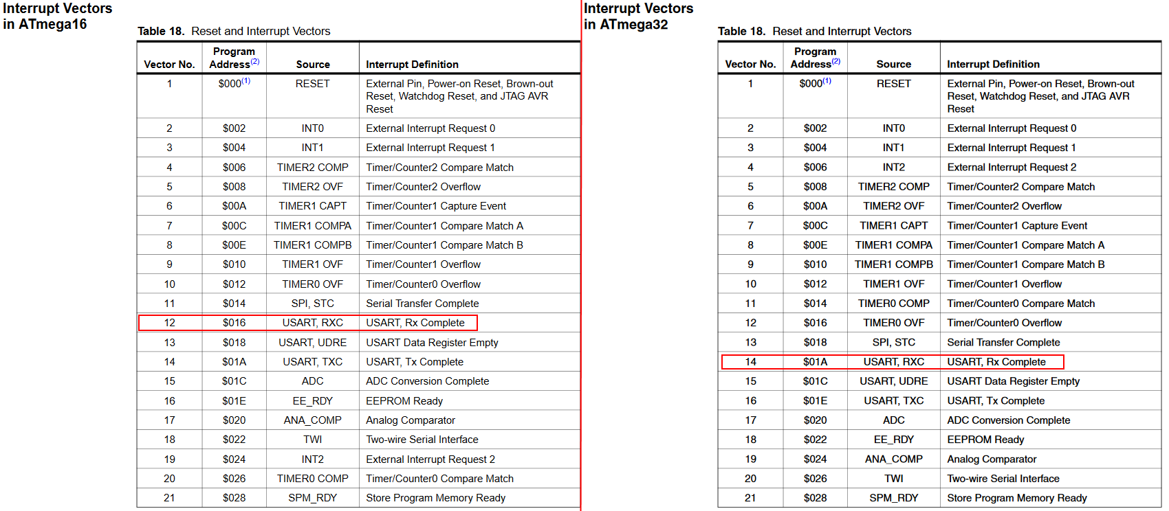
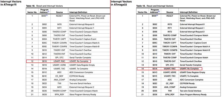
Tabelle der Interrupt-Vektoren für ATmega16 und ATmega32
Definition 1 | $000 | RESET | External Pin, Power-on Reset, Brown-out Reset, Watchdog Reset, and JTAG AVR Reset 2 | $002 | INT0 | External Interrupt Request 0 3 | $004 | INT1 | External Interrupt Request 1 4 | $006 | TIMER2 COMP | Timer/Counter2 Compare Match 5 | $008 | TIMER2 OVF | Timer/Counter2 Overflow
in „Hex File von Atmega16 in Atmega32 verwandeln“ · Mikrocontroller und Digitale Elektronik · · Screenshots
-
PDF
Component_tester_T7-dreieck.pdf
board, connected to pads of removed U4. See https://www.mikrocontroller.net/topic/transistortester-avr?goto=7280477#7280477 Power control (on separate board). Based on http://mikrocontroller.net/topic/transistortester-avr?goto=6439712#6439712 License of Schematic: GFDL 1.3 (http://gnu.org/licenses/fdl
-
Datei
MD_NMRA_DCC.h
init, cv5_init, cv6_init, cv7_init, cv8_init, cv9_init, cv10_init, cv11_init, cv12_init, cv13_init, cv14_init, cv15_init, cv16_init, cv17_init, cv18_init, cv19_init, cv20_init, cv21_init, cv22_init, cv23_init, cv24_init, cv25_init, cv26_init, cv27_init, cv28_init, cv29_init, cv30_init, cv31_init, cv32_init
in „FULL NMRA DCC Library, Encoder, Generator, Bremsmodul“ · Projekte & Code ·
-
Datei
main.c
AlphaController.c * * Created: 08.10.2020 11:02:15 * Author : Yll */ #define F_CPU 16000000UL #include <avr/io.h> #include <avr/interrupt.h> int rhythm [101]= {1, 2, 2, 4, 5, 2, 3, 1, 8, 10, 10, 2, 2, 6, 2, 3, 8, 1, 3, 20, 3, 1, 2, 5, 25, 6, 2, 1, 1, 2, 3, 7, 32, 16, 6, 4, 2, 2, 1, 1, 1, 2, 2, 3, 4, 5, 7,
in „Probleme Leistungssteuerung mit UART und AVR“ · Mikrocontroller und Digitale Elektronik ·
-
Datei
showbmp_anleitung.txt
girlie.bmp > girlie_avrpix.txt Hierbei entsteht dann eine Textdatei "girlie_avrpix.txt" die durch den AVR-GCC verarbeitet werden kann. Die Textdatei stellt ein einziges Datenarray mit dem Namen -- bmppic -- zur Verfügung. Soll diese Textdatei für einen anderen Controller erzeugt werden, so dürfte die Quelldatei
in „Bild mit 1 Bit Farbtiefe auf 240 x 120“ · Mikrocontroller und Digitale Elektronik ·
-
Datei
vs1011_1.c
Analog volume control SS VER is 0 for VS1001, 1 for VS1011, 2 for VS1002 and 3 for vs1003. */ #include <avr/io.h> #include <avr/interrupt.h> #include <avr/signal.h> #include <string.h> //#include <avr/eeprom.h> #include <stdio.h> //für devopen /* UART-Init beim ATmega8 bzw.16 */ #define F_CPU 16000000 #define
in „Sinustest des vs1011“ · Mikrocontroller und Digitale Elektronik ·
-
Datei
HW-PWM_an_3_Pins.c
/* Microcontroller: ATmega8515 Clock: 14,745 MHz AVR hardware: timer2 */ #include <avr/io.h> #include <util/delay.h> /// Number of probes for one period of sine wave #define WAVE_PROBES 256 /* predefined values */ uint8_t wave[WAVE_PROBES]
in „Umschalten von 3 HW-PWM Kanälen beim ATMEGA8515“ · Mikrocontroller und Digitale Elektronik ·
-
Datei
USI_TWI_Slave.h
Atmel Corporation * * File : USI_TWI_Slave.h * Compiler : IAR EWAAVR 4.11A * Revision : $Revision: 1.14 $ * Date : $Date: Friday, December 09, 2005 17:25:38 UTC $ * Updated by : $Author: jtyssoe $ * * Support mail : avr@atmel.com * * Supported devices : All device with USI module can be used. * The example
in „AVR: I2C bleibt hängen“ · Mikrocontroller und Digitale Elektronik ·
-
Datei
SRF08.c
//Includes ----------------------- #include <avr/io.h> #include <avr/interrupt.h> //-------------------------------- //Status Codes -------------------- #define START_TRANSM 0x08 #define REP_START_TRANSM 0x10 #define SLAW_TRANSM_ACK_RECIE 0x18 #define
in „AVR: SRF08: NACK wird empfangen“ · Mikrocontroller und Digitale Elektronik ·