-
PDF
DS1220Y.pdf
-100 UNITS NOTES MIN MAX Read Cycle Time tRC 100 ns Access Time tACC 100 ns OE to Output Valid tOE 50 ns CE to Output Valid tCO 100 ns OEor CE to Output Active tCOE 5 ns 5 Output High-Z from Deselection tOD 35 ns 5 Output Hold from Address Change tOH 5 ns Write Cycle Time t 100 ns WC Write Pulse Width
in „[S] DALLAS DS1220Y-150 NVRAM (NOS)“ · Analoge Elektronik und Schaltungstechnik ·
-
Bild
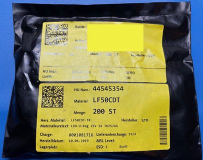
Etikett einer Elektronikkomponenten-Verpackung
HU Num.: 44545354 Material: LF50CDT Menge: 200 ST Hers. Material: LF50CDT-TR Hersteller: STM Materialkurztext: LDO-U-Reg +5V 1A T0252AA Lieferantencarge: 1924 Herstelldatum: 10.06.2019 MSL Level: Lagerplatz: ESD: E RoHS
in „V: TLE5205-2S, L298N, LF50CDT, ATSAM4S16CB, LPC2136FBD64, AD5259BRMZ10, LD274-3“ · Markt · · Fotos
-
PDF
BME280_Datasheet.pdf
Operating range only for non-condensing environment. 4 For hysteresis measurement the sequence 103050709070503010 %RH is used. The hysteresis is defined as the difference between measurements of the humidity up / down branch and the averaged curve of both branches 5 Non-linear contributions to
in „PIC18F, Sensor auslesen I2C“ · Mikrocontroller und Digitale Elektronik ·
-
PDF
ADT7420.pdf
Rev. 0 | Page 7 of 24 ADT7420 Data Sheet TYPICAL PERFORMANCE CHARACTERISTICS 30 1.00 0.75 25 ) C 0.50 ) ( A 20 R MAX ACCURAC YLIMITS ( R 0.25 D R ID E N E 0 W 15 U O T T R–0.25 U E S 10 5.5V P MAX ACCURAC Y LIMITS E–0.50 5.0V T 5 4.5V –0.75 3.6V 3.3V 3.0V 2.7V 7 0 2 –1.00 - –100 –50 0 50 100 150 200
in „STM32F4 mit I2C-Sensor“ · Mikrocontroller und Digitale Elektronik ·
-
PDF
0900766b8147ba33.pdf
. 30 V DC – Spannbügel – Frontrahmen f. Schraubbefestigung (T008181) 56 x 40 mm, Einbauquerschnitt 50 x 25 mm – Frontrahmen f. Spannbügelbefestigung (T008180) 53 x 28 mm, Einbauquerschnitt 50 x 25 mm – Dichtung – Bedienungsanleitung multilingual 1) Lagertypen 220 www.kuebler.com © Fritz Kübler GmbH,
in „[V] Diverses“ · Markt ·
-
PDF
LEM-HAS_50-S-datasheet.pdf
Current Transducer HAS 50 .. 600-S I PN = 50 .. 600 A For the electronic measurement of currents: DC, AC, pulsed..., with galvanic isolation between the primary circuit (high power) and the secondary circuit (electronic circuit). Electrical data Type Primary nominal Primary current, RoHS since 1) current rms measuring range date code I (A) I (A) PN PM HAS 50-S 50 ± 150 45217 Features HAS 100-S 100 ± 300 45325 HAS 200-S 200 ± 600 45166 ●● Hall effect measuring principle ●● Galvanic isolation
-
Bild
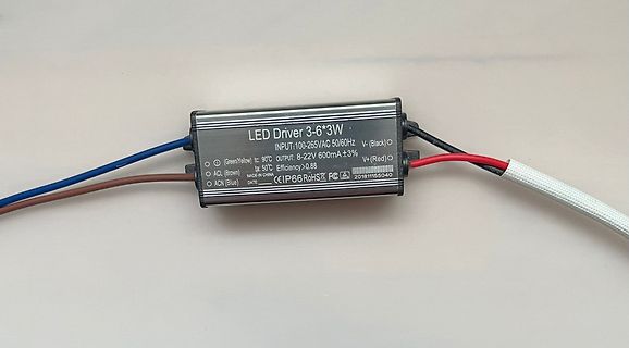
LED-Treiber mit Anschlusskabeln
LED Driver 3-6*3W INPUT:100-265VAC 50/60Hz OUTPUT: 8-22V 600mA±3% (Green)Yellow tc: 90°C tc: 50°C Efficiency >0.88 V- (Black) V+ (Red) ACL (Brown) ACN (Blue) MADE IN CHINA CE IP66 RoHS FC 201811155040
in „Suche Empfehlung zu gutem CC Netzteil“ · Analoge Elektronik und Schaltungstechnik · · Fotos
-
PDF
An_Ceramic_Cellular_1204_DB_CHE_0.pdf
Tape & reel automatic PART NUMBER mounting Reflow process compatible ANT 1204 L L00 R 0918A RoHS compliant (1) (2) (3) (4)(5) (6) 1 PRODUCT APPLICATIONS ANT = Antenna Global cellular network 2 SIZE devices 1204= 12*4 Telematics Cellular broadband access 3 ANTENNA TYPE M2M module L,F,A =
in „GSM PCB-Antenne: Matching in beide Richtungen?!“ · HF, Funk und Felder ·
-
PDF
Power_Supply_715G6503-P01-001-0010_Philips_______red_S.1.pdf
a b R905 +19V 1 68K +-1% 1/10W 6 For EMI Solution 2 R906 3 12K 5% 1/4W C920 C908 4 100PF1KV 0.1uF 50V 5 HV 6 6 7 ON/OFF 7 R907 For under FTS 0.1W Solution D S 8 DIM 1 MOHM +-5% 1/4W + 4 S 9 3 BP S 10 R908 R909 C910 2 CP S 11 1 MOHM +-5% 1/4W 1 MOHM +-5% 1/4W 10uF/50V C912 1 FB S 12 100P 50V PD S R910
in „Fujitsu B27T-7 TFT Monitor Netzteil defekt Bauteil 715G6503-P01-001-0010“ · Analoge Elektronik und Schaltungstechnik ·
-
Bild
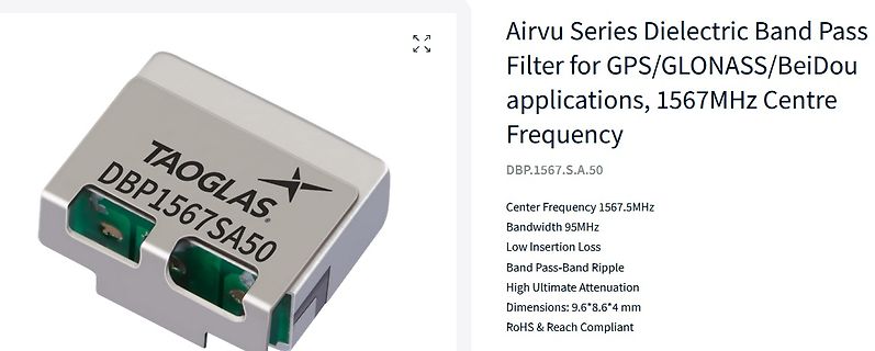
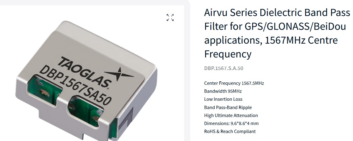
Taoglas Dielectric Band Pass Filter
Dielectric Band Pass Filter for GPS/GLONASS/BeiDou applications, 1567MHz Centre Frequency DBP.1567.S.A.50 Center Frequency 1567.5MHz Bandwidth 95MHz Low Insertion Loss Band Pass-Band Ripple High Ultimate Attenuation Dimensions: 9.6*8.6*4 mm RoHS & Reach Compliant TAOGLAS. DBP1567SA50
in „Bauteil aus russischer Drohne identifizieren“ · HF, Funk und Felder · · Screenshots
-
PDF
Comchip__CDBQC0130L-HF_RevD.pdf
....... ....... ....... Start 160mm (min) 400mm (min) Direction of Feed SYMBOL A B C d D D 1 D 2 1.50+0.10 0402C (mm) 0.75±0.05 1.17±0.05 0.65±0.05 - 0 178.00±1.00 60.00±0.50 13.50±0.20 (SOD-923F) 0.059+0.004 (inch) 0.030±0.002 0.046±0.002 0.026±0.002 - 0 7.008±0.039 2.362±0.020 0.531±0.008 SYMBOL E F P P0 P1 T W W 1 0.20+0.02 12.00+0.50 (SOD-923F) (mm) 1.75±0.10 3.50±0.10 4.00±0.10 4.00±0.10 2.00±0.10 -0.05 8.00±0.20 - 0 (inch) 0.069±0.004 0.138±0.004 0.157±0.004 0.157±0.004 0.079±0.004 0.008+0.001 0.315±0.008 0.472+0.020 -0.002 - 0
in „Spannungsteiler: niedrigere Ausgangsspannung bei 90 °C“ · Analoge Elektronik und Schaltungstechnik ·
-
PDF
833H.pdf
time 5ms Max. (1) Insulation resistance 100M 7 Min. (DC 500V) (1) Between open contact :AC 750V , 50/60Hz 1 min. Dielectric strength Between contact and coil :AC 1500V , 50/60Hz 1 min. Operating extremes 10~50Hz , amplitude 1.5 mm Vibration resistance Damage limits 10~50Hz , amplitude 1.5 mm Operating
in „LPT-Interface Elektronik-Optimierung“ · Mikrocontroller und Digitale Elektronik ·
-
PDF
899-1203726.pdf
Release time (1) 5ms Max. Insulation resistance1) 100M 7 Min. (DC 500V) Between open contact : AC 750V , 50/60Hz 1 min. (1) : AC 1000V , 50/60Hz 1 min. (for 899B type) Dielectric strength Between contact and coil : AC 1500V , 50/60Hz 1 min. : AC 2000V , 50/60Hz 1 min. (for 899B type) 10Д50Hz , amplitude 1.5 mm Vibration resistance Operating extremes Damage limits 10Д50Hz , amplitude 1.5 mm Operating extremes 10G Shock resistance Damage limits 100G 10,000,000 operations Mechanical (frequency 18,000 operations/hr) Life expectancy 100,000 operations Electrical (frequency
in „Bauteil Identifizierung“ · Analoge Elektronik und Schaltungstechnik ·
-
PDF
_D03019040G-00_-3.pdf
39 D0~D9 130~139 N0~N9 230~239 Y0~Y9 330~339 40~49 40~49 E0~E9 140~149 P0~P9 240~249 Z0~Z9 340~349 50~59 50~59 F0~F9 150~159 Q0~Q9 250~259 60~69 60~69 G0~G9 160~169 R0~R9 260~269 70~79 70~79 H0~H9 170~179 S0~S9 270~279 80~89 80~89 I0~I9 180~189 T0~T9 280~289 90~99 90~99 J0~J9 190~199 U0~U9 290~299 建
in „Leiser Gerätelüfter in 35x35 gesucht“ · Mechanik, Gehäuse, Werkzeug ·
-
PDF
datasheet-2357993-sunon-mf80252v11000ua99-axial-fan-24-v-dc-6964-mh-l-x-w-x-h-80-x-80-x-25-mm.pdf
39 D0~D9 130~139 N0~N9 230~239 Y0~Y9 330~339 40~49 40~49 E0~E9 140~149 P0~P9 240~249 Z0~Z9 340~349 50~59 50~59 F0~F9 150~159 Q0~Q9 250~259 60~69 60~69 G0~G9 160~169 R0~R9 260~269 70~79 70~79 H0~H9 170~179 S0~S9 270~279 80~89 80~89 I0~I9 180~189 T0~T9 280~289 90~99 90~99 J0~J9 190~199 U0~U9 290~299 建
in „Lüftersteuerung für Verstärker funktioniert nicht zuverlässig“ · Analoge Elektronik und Schaltungstechnik ·
-
Bild
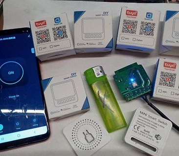
Tuya Smart Switch Verpackungen, Smartphone, Platine und Feuerzeug
WiFi Zigbee ON Power On Timer setting MiNi Smart Switch WiFi:IEEE802.11 b/g/2.4GHz Input:AC100-240V 50/60Hz Output:AC100-240V 50/60Hz Current:10A CE RoHS Made in China L-out L-in N-in N-out S1 S2
in „China SUPER Bauteile-Schnäppchen Thread [V4]“ · Markt · · Fotos
-
Bild
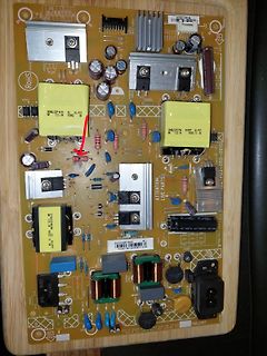
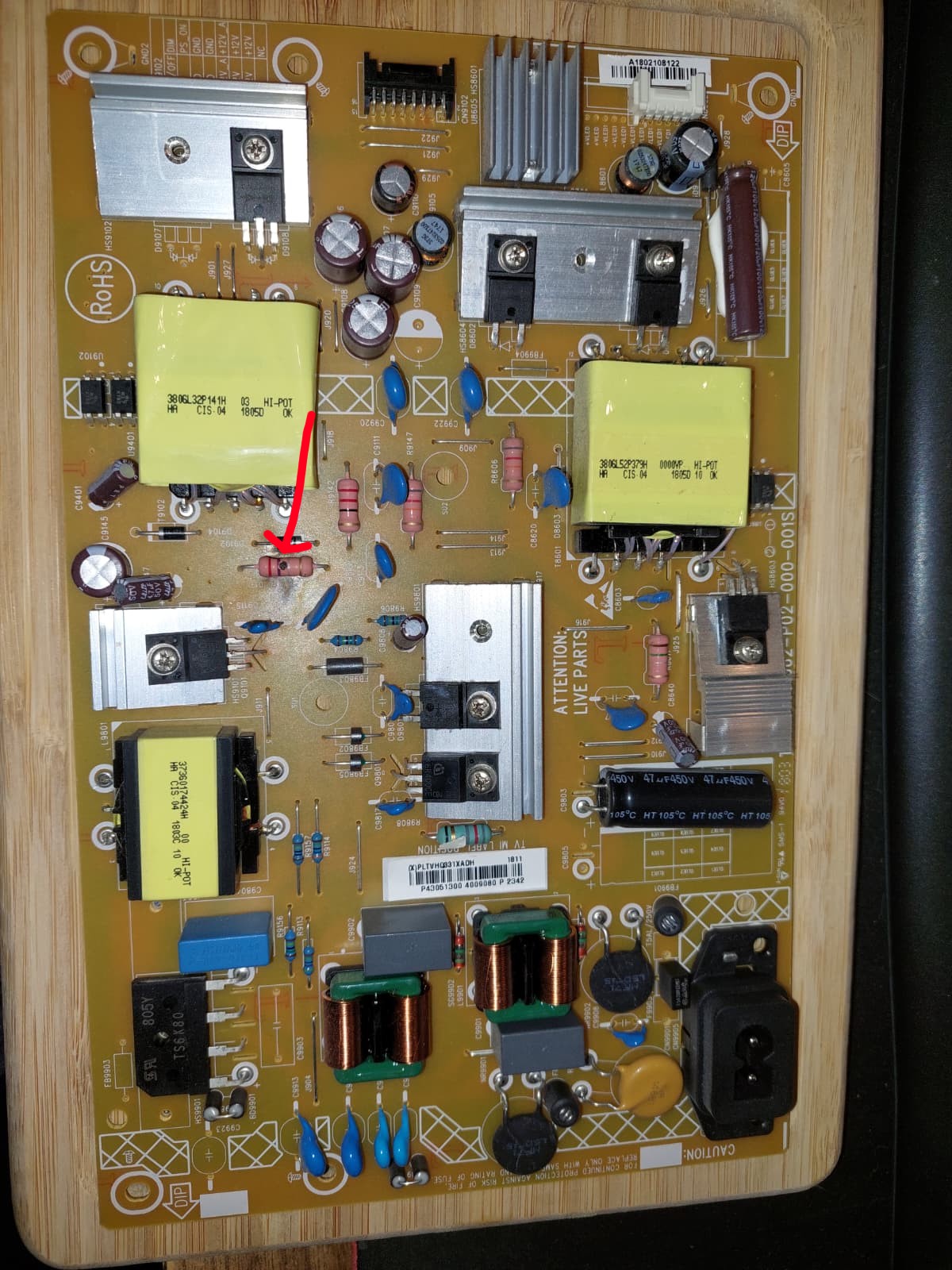
Leiterplatte eines Schaltnetzteils
RoHS, 301W2.32F14H, HI-POT, 10k, 03, CIS 04, 18J50, 301W2.32F57H, 0000PF, HI-POT, 10k, 18J50, CIS 04, ATTENTION: LIVE PARTS, 400V, 105°C, 400V, 105°C, 100, 400V, 105°C, 100, 400V, 105°C, 100, 800V, 105°C,
in „Netzteil von Philips TV reparieren möglich?“ · Analoge Elektronik und Schaltungstechnik · · Platinenfotos
-
Bild
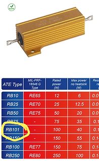
Leistungswiderstand und Tabelle mit Spezifikationen
RoHS ATE R850 R12 J 0821 ATE Type MIL-PRF-18546 G Type Rated power (W) Max power no heatsink (W) RB10 RE65 12 6 RB25 RE70 25 12.5 RB50 RE75 50 20 RB75 75 35 RB101 100 40 RB150 150 55 RB100 RE77 150 75 RB250
in „[F]rage: Braucht jemand mehrere 330 Ohm 100W-Widerstände?“ · Markt · · Screenshots
-
PDF
Sanken_PF.pdf
Features s i(1) 72) , ● Thermal Fatigue Capability: 5,000 cyc.h Reliability SDffix “S”Z 2 7 S ● RoHS Compliantability e w Suffix VR”1) (2Z 2 Applications N 7 V V Not to scale ● Alternator Circuit for the 12 V Batteryfouto(1)iveC 1SCathodeSW SuAnode“R” e d (G) - 1 -ACode Cathode Typical Application n
in „Identifikation von Dioden erbeten“ · Fahrzeugelektronik ·
-
PDF
Stollmann_Blue_RS_I_en.pdf
Max Frequency Range 2400 2483.5 MHz Measured with network Load impedance analyzer in the frequency 50 Ω range at antenna pin Receive Mode to 50Ω load -10 Output return loss dBm Transmit Mode to 50Ω -10 load The typical voltage is Supply voltage U3 recommended Vcc at 3.23 3.3 3.37 Vdc variant. voltage
in „Bluetooth RSSI auslesen > (grobe) Entfernungsmessung per B“ · Mikrocontroller und Digitale Elektronik ·
-
PDF
APW7080.pdf
• Thermal-Enhanced SOP-8P Package 80 ) 70 • Lead Free and Green Devices Available ( VOUT =3.3V (RoHS Compliant) y 60 n c 50 f 40 Applications E 30 20 • LCD Monitor / TV • Set-Top Box 10 • Portable DVD 0.001 0.01 0.1 1 10 Output Current, I (A) • Wireless LAN OUT • ADSL,SwitchHUB • Notebook Computer •
-
Bild
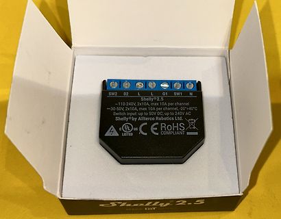
Shelly 2.5 Smart Switch in Verpackung
Shelly 2.5 SW2 02 L L 01 SW1 N ~110-240V, 2x10A, max 10A per channel -30-50V, 2x10A, max 10A per channel, -20-+40°C Switch input: up to 50V DC; up to 240V AC Shelly® by Allterco Robotics Ltd. UL LISTED CE RoHS COMPLIANT Shelly 2.5 MAKE IoT
in „[V] Shelly Aktoren, Vocolink Leuchtmittel # (Homeautomation)“ · Markt · · Fotos
-
PDF
rt8016_richtek_FT8.pdf
Transient Response Load Transient Response V = 3.6V, V = 1.2V IN OUT V IN= 3.6V, OUT = 1.2V IOUT= 50mA to 1A IOUT = 50mA to 0.5A V OUT VOUT (50mV/Div) (50mV/Div) IOUT OUT (500mA/Div) (500mA/Div) Time (50μs/Div) Time (50μs/Div) Copyrigh© 2012 Richtek Technology Corporation. All rights reserved. is a
-
PDF
kit160-6.pdf
BISZU256MAKROSPROGRAMMIERBAR * TEXTUNDGRAFIKMISCHEN * PULL-DOWNMENÜS * BETRIEBSTEMPERATURBEREICH0..+50°C ZUBEHÖR * INTEGRIERTESTOUCHPANELMIT8x4FELDERN(ENTSPIEGELT,KRATZFEST) * DISKETTEFÜRMAKROPROGRAMMIERUNG(PC-DOS):EADISK240 * KABEL(1,5m)FÜRANSCHLUSSAN9-POL.SUB-D(RS-232FEMALE):EAKV24-9B BESTELLBEZEICHNUNG
in „Display ansteuern - Fehler“ · Mikrocontroller und Digitale Elektronik ·
-
PDF
Drehimpulsgeber.pdf
NT Features Applications PIA OM ■ Push switch option Level control, tuning and timer settings in: HS C *Ro ■ Compact, rugged design ■ Audio-visual equipment ■ High reliability ■ Consumer electric appliances ■ Metal bushing/shaft ■ Radios ■ Musical instrumentation ■ Communications equipment PEC11 Series
in „Drehimpulsgeber“ · Mikrocontroller und Digitale Elektronik ·
-
Datei
SteueruC.asm
************************************** ; Configuration festlegen: ; Power on Timer, kein Watchdog, HS-Oscillator, kein Brown out, kein LV-programming __CONFIG _PWRTE_ON & _WDT_OFF & _HS_OSC & _BODEN_OFF & _LVP_OFF ;********************************************************** Zeichen equ 0x20 RXData equ
in „PIC16f876A UART Puffer“ · Mikrocontroller und Digitale Elektronik ·
-
PDF
Inkrementgeber_PEC11.pdf
NT Features Applications PIA OM ■ Push switch option Level control, tuning and timer settings in: HS C *Ro ■ Compact, rugged design ■ Audio-visual equipment ■ High reliability ■ Consumer electric appliances ■ Metal bushing/shaft ■ Radios ■ Musical instrumentation ■ Communications equipment PEC11 Series
in „Inkrementalencoder mit 2-bit gray code“ · Mikrocontroller und Digitale Elektronik ·
-
PDF
S20_EU.SCH.pdf
2 2 J 2 J 1 1 1 1 1 3 | | 1 1 1 VDDA-1 LNA 2 1 C27 2 6 K K 3 VDD3V3-1 R | R 1 R 1 4 VDD3V3-2 10PF/50V/0603 J 30 VDDA-2 VDD-RTC5 R 11 VDDPST-1 TOUT 6 1 1 1 T1 17 VDDPST-2 F E S 29 VDDD - - R VCC-3V3 E E - VCC_BAR MTMS 9 SCL E MTDI 10 PWM0 16 GPIO4 MTCK 12 PWM1 U6 24 GPIO5 E-CMD 1 CS# VCC 8 MTDO 13 PWM2
in „SonOff S20 Leben, wirken und widerbelebung. :-)“ · Haus & Smart Home ·
-
PDF
drv103.pdf
Delay Delay 0 0 +V S On +V S On 3 3 R L I R L I 2 U 2 U ( ( AVG 1 ) IAVG 1 ) 0 Pull-In 0 0 0 On 0 50 100 0 50 100 Time (ms) Time (ms) QUIESCENT CURRENT CURRENT LIMIT SHUTDOWN WAVEFORMS vs JUNCTION TEMPERATURE 5.0 FPWM = 25kHz 4.5 DC = 50% 4.0 On Delay = 150µs 5 V VIN Reset Period = 1PWM N 3.5 Off Off
in „PWM Signal wie stell ich das ein?“ · Mikrocontroller und Digitale Elektronik ·
-
PDF
ADum1200pdf.pdf
which the specified pulse-width distortion is guaranteed. 4tPHLpropagation delay is measured from the 50% level of the falling edge of theIx signal to the 50% level of the falling edge ofOxhe V siPLHpropagation delay is measured from the 50% level of the rising edge of the Ixsignal to the 50% level of the
in „ADum1200 Digitalisolator“ · Mikrocontroller und Digitale Elektronik ·
-
PDF
ADUM1201.pdf
which the specified pulse-width distortion is guaranteed. 4tPHLpropagation delay is measured from the 50% level of the falling edge of theIx signal to the 50% level of the falling edge ofOxhe V siPLHpropagation delay is measured from the 50% level of the rising edge of the Ixsignal to the 50% level of the
in „Mega8 funktioniert ohne Versorgungsspannung :)“ · Mikrocontroller und Digitale Elektronik ·
-
PDF
PMR209-Nachfolger-P409.pdf
UL, cUL Peak Pulse Voltage 1,000 V The series resistance is defined at 1 kHz for RC ≥ 50 µs and at Series Resistance 100 kHz for RC < 50 µs Minimum Values Between Terminals Insulation Resistance C ≤ 0.33 µF ≥ 3,000 MΩ C > 0.33 µF ≥ 1,000 MΩ • µF Maximum 12 A repetitive. Maximum 20 A peak
in „Fehlerhafte RPI gesteuerte TRIAC-Schaltung für AC-Lasten“ · Platinen ·
-
Bild
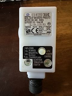
Netzteil mit Funktionsbeschreibungen
GOLDEN POWER MODEL NO:GP-SW310DC0193-IP44(EU)-1CT INPUT/PRI:100V-240V~ 50/60Hz OUTPUT/SEC:31V= 193mA 6W Uout=33V= 75°C SELV TIMER 6H RoHS IP44 SGS GS CE NINGBO GOLDEN POWER ELECTRONIC CO., LTD. MADE IN CHINA 100% COMB 75% IN WAVES 50% SEQUENTIAL 25% SLO-GLO WITH REMOTE CONTROL
in „Wie funktioniert das Netzteil ?“ · Analoge Elektronik und Schaltungstechnik · · Fotos
-
Bild
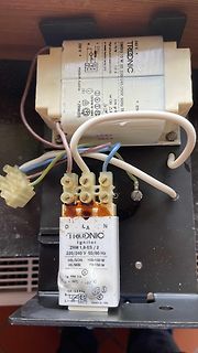
Tridonic Ignitor ZRM 1,8-ES mit Verkabelung
TRIDONIC OMIS to W 65 230/250V 1,0 A made in Austria ZRM(D) OSRAM W-0385 50Hz TF Nr. 130 230 V L N G E N D L A N TRIDONIC Ignitor ZRM 1,8-ES / 2 220/240 V 50/60 Hz HS/SON 100-150 W HI/MBI 70-150 W IB max. 2A tc = -30°C + 90°C 4,0 - 4,5 kV N L Osram 0-420
in „Umrüstung HQI von Drossel auf EVG“ · Haus & Smart Home · · Fotos
-
PDF
ADS1293_3_Kanal_24BIT_EKG_SPI_.pdf
Consumption BW CLOAD CMDET CMDET_BW CMDET_CAPDRIVE SUPPLY (kHz) (nF) (µA) 0: Low BW 00: Low Cap Drive 50 2 39 mode 0: Low BW 01: Medium Low Cap Drive 50 3.3 45 mode 0: Low BW 10: Medium High Cap Drive 50 4.5 56 mode 0: Low BW 11: High Cap Drive 50 8 75 mode 1: High BW 00: Low Cap Drive 150 0.4 43 mode 1
in „EKG-IS ADS1293 rückt keine Messwerte raus“ · Mikrocontroller und Digitale Elektronik ·
-
PDF
ADS1293_3_Kanal_24BIT_EKG_SPI_Dez_2014.pdf
Consumption BW CLOAD CMDET CMDET_BW CMDET_CAPDRIVE (kHz) (nF) ISUPPLY (µA) 0: Low BW mode 00: Low Cap Drive 50 2 39 0: Low BW mode 01: Medium Low Cap Drive 50 3.3 45 0: Low BW mode 10: Medium High Cap Drive 50 4.5 56 0: Low BW mode 11: High Cap Drive 50 8 75 1: High BW mode 00: Low Cap Drive 150 0.4 43 1: High
in „Warum soll ADS1293 mit einem 4,096 MHz Quarz betrieben werden?“ · Mikrocontroller und Digitale Elektronik ·
-
PDF
TPD2015FN_application_note_en_20230207_AKX01102.pdf
𝑡𝑤= 3.6 𝑚𝑠 …Value based on actual measurements Table 7.1 Loss breakdown (V DD(opr) 24 V, fPWM = 50 Hz, Duty = 50 %, I load= 0.48 A) V V I R duty tON tOFF L f Loss item (CL)OUT Load DSON PWM ch 数 (V) (V) (mA) (Ω) (%) (μs) (μs) (mH) (Hz) (W) A Constant loss 24 4.2 1 0.1008 Conduction loss 480 0.55 50% 1 0.0634 B Switching loss 24 480 50% 10 6 50 1 0.0017 Reverse power loss -1.3 480 50 50 1 1.0339 total 1.1998 Fig. 7.1 Internal block diagram and external connection conditions example 12 2023-02-07 © 2023 Toshiba Electronic Devices &
in „(S) PNP-Transistorarray“ · Analoge Elektronik und Schaltungstechnik ·
-
PDF
MAS6180C.pdf
A A P 0 Tape Feed Direction T Section A - A B0 S 1 K0 Pin 1 Designator Dimension Min Max Unit A0 6.50 6.70 mm B0 5.20 5.40 mm D 0 1.50 +0.10 / -0.00 mm D 1.50 mm 1 E1 1.65 1.85 mm F1 7.20 7.30 mm K0 1.20 1.40 mm P 11.90 12.10 mm P0 4.0 mm P2 1.95 2.05 mm S1 0.6 mm T 0.25 0.35 mm W 11.70 12.30 mm 10 (
-
PDF
cfspc3_0.pdf
Socket Connector Entry Description Pin Number L ± 0.10 L1 Max L2 Ref L3 ± 0.10 L4 Power 1, 13, 38 & 50 5.00 [.197] 0.50 [.020] 4.50 [.177] 0.50 [.020] 0.50 - 2.50 [.020 - .098] General All other pins 4.25 [.167] 0.50 [.020] 3.75 [.148] 0.50 [.020] 0.50 - 2.50 [.020 - .098] Detect 25, 26 3.50 [.138] 0.50
in „Lucky-page@gmx.de“ · Mikrocontroller und Digitale Elektronik ·
-
PDF
netzteil5v3a.pdf
264 VAC Hi-Pot 3000 Vac/1sec @ 5mA Line Frequency 47 - 63 Hz (primary - secondary) ≦0.25mA,at 264VAC/50Hz Current 400mA at 100-240VAC Leakage Current Configuration IEC-320, C8, 2PIN Hold Up Time ≧6mSec Standby Power ≦0.3 Watt (As per EPS Output Consumption Guideline) Model Name Voltage Current Watt EfficiencEMI
in „Netzteil mit 1,5 Meter Kabel; Störungen vorsorgen mit Kondensator?“ · Mikrocontroller und Digitale Elektronik ·
-
PDF
FELDER-Katalog-2012.pdf
eutektisch Sn60Pb40 S-Sn60Pb40 Sn60Pb40 183 - 190 °C Sn60Pb38Cu2 S-Sn60Pb39Cu1 Sn60Pb38Cu02 183 - 190 °C Pb50Sn50 S-Pb50Sn50 Sn50Pb50 183 - 215 °C bleihaltig Pb60Sn40 S-Pb60Sn40 Sn40Pb60 183 - 235 °C Pb70Sn30 S-Pb70Sn30 Sn30Pb70 183 - 255 °C Pb93Sn5Ag2 S-Pb93Sn5Ag2 Sn05Pb93Ag02 296 - 301 °C Weitere Legierungen
in „Lötspitzen-Modifikation“ · Mechanik, Gehäuse, Werkzeug ·
-
PDF
RJLB-239TC1-A1_RJPLB-203TC1-replacement_20100805.pdf
/05 R(REV:A1) Single 10/100 BASE-TX Filtered Connector Module MODELNO. : RJLB-239TC1 Features: ◎ RoHS Compliant ◎ Fully shielded magnetics protect data from internally generated digital noise ◎ Reduces the overall length of the signal path for improved common mode performance ◎ Implements full common
-
PDF
ARS5045.pdf
auto motive requirements F(AV) 50 A V 45 V ● Using Planar SKY barrier chip RRM ● High surge capability IFSM 720 A ● Low cost construction utilizing void-free molded plastic TJ MAX 175 °C technique ● Compliant to RoHS Directive 2011/65
in „Ausgleichstromverhinderer/Galvanic Ground Isolation“ · Fahrzeugelektronik ·
-
PDF
iW1816.pdf
with Power BJT and OTP 8 Typical Performance Characteristics 4.58 12.0 ) 4.54 ( 11.6 l ) h ( s O4.50 r 11.2 L T V p U4.46 - 10.8 C r V t 4.42 S 10.4 C V 4.38 10.-50 -25 0 25 50 75 100 125 150 -50 -25 0 25 50 75 100 125 150 Ambient Temperature (ºC) Ambient Temperature (ºC) Figure 8.1 : V CC UVLO vs.
in „Fritz Powerline 540E abgeraucht“ · Mikrocontroller und Digitale Elektronik ·
-
PDF
nichicon-ul.pdf
5000 hours at +105 °C . Designed for surface mounting on high density PC board. Compliant to the RoHS directive (2011/65/EU). CB Long Life Long Life UA UL Specifications Item Performance Characteristics Category TemperatureRange –40 to +105°C Rated Voltage Range 6.3 to 50V Rated Capacitance Range 0.1
in „Kondensatortausch auf gebrauchter Platine“ · Analoge Elektronik und Schaltungstechnik ·
-
Bild
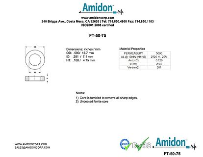
Datenblatt eines Ferritkerns FT-50-75
Amidon FT-50-75 www.amidoncorp.com 240 Briggs Ave., Costa Mesa, CA 92626 | Tel: 714.850.4660 Fax: 714.850.1163 ISO9001:2008 certified Dimensions: inches / mm OD: .500/ 12.7 mm ID: .281 / 7.1 mm HT: .188 / 4.75 mm
in „RF Verstärker mit "Resonanz" bei 7 MHz“ · HF, Funk und Felder · · Screenshots
-
PDF
Mini-Circuits-ADE-1-datasheet.pdf
excellent L-R isolation, 55 dB typ. Storage Temperature -55°C to 100°C PRICE: $2.49 ea. QTY (20) RF Power 50mW • excellent IP3, 15 dBm typ. • low profile package +RoHS Compliant IF Current 40mA The+SuffixidentifiesRoHSCompliance.Seeour website Permanent damage may occur if any of these limits are • aqueous
in „Ringmodulator“ · Analoge Elektronik und Schaltungstechnik ·
-
PDF
Pana_HA.pdf
Vibration-proof product (30G guaranteed) is available upon request (ø8 ≦) ● AEC-Q200 compliant ● RoHS compliant Specifications Category temp. range –40 ℃ to +105 ℃ Rated voltage range 6.3 V to 100 V Capacitance range 1 μF to 1500 μF Capacitance tolerance ±20 % (120 Hz / +20℃) Leakage current I ≦ 0.01
in „Display vom Kühlschrank reparieren“ · Haus & Smart Home ·
-
PDF
BlueMOD_P25_G2__Datasheet.pdf
Max Frequency Range 2400 2483.5 MHz Measured with network Load impedance analyzer in the frequency 50 Ohm range at antenna pin Receive Mode to 50Ω load -10 Output return loss dBm Transmit Mode to 50Ω load -10 The typical voltage is Supply voltage VSUP recommended VSUP at 2.8 3.3 3.6 Vdc voltage pin Ripple
in „Bluetooth-Modul "BlueMod+P25" von Stollmann - Ersatztyp“ · Mikrocontroller und Digitale Elektronik ·